RC-ONE a KIM-1 clone

Tor-Eirik Bakke Lunde a.k.a TEBL created several computer systems with detailed documentation.

The RC-ONE is a KIM-1 clone, inspired by the design by Ruud Baltissen, which can be built in a compact to much expanded format.

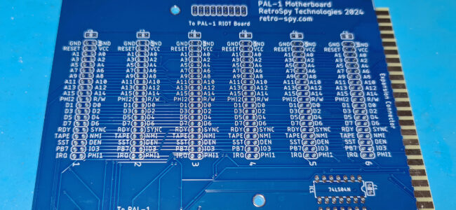
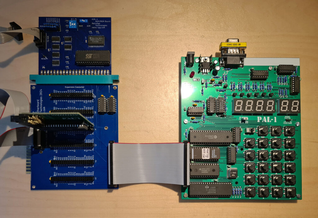
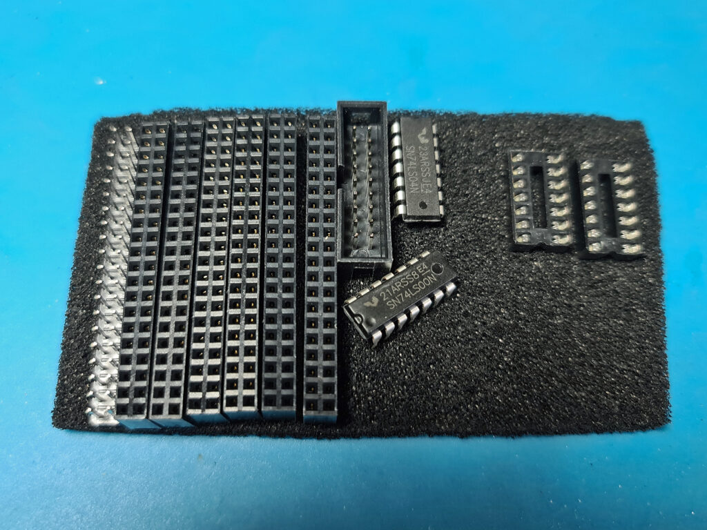
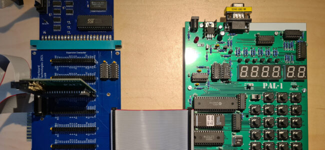
TEBL separated functionality into separate boards so that each version would cost only around 5$ per piece instead. It means it’s no longer a single board computer, but if it means more people can build it as a fun project then that’s a plus in my book. The main setup does not include the additional 15 I/O lines due to space requirements, but you can add those back to the system by including the 65K Expansion (in addition to the backplane module) if you want to. If you just want to play around with the system and try your hand at machine language coding, you can get started with the CPU board, UI board and a keypad module.
The whole design is documented on TEBLs github page, from circuit diagrams to PCB design.

The manual is an excellent guide to the system, read that first!

Instandsetzung und Nachbau eines KIM-1

Ralf (Ralf02, forum64.de) started a thread on the forum64 called Instandsetzung und Nachbau eines Kim-1 in March 2022.
99 pages further of designs and discussions in the thread, delivered a working KIM-1 that is closer to the original KIM-1 than any KIM-1 replica designed. A great achievement and a well deserved compliment to Ralf!

The work of Ralf is not limited to the KIM-1 replica itself. He also designed a KIM I/O module and a 1541 IEC/RAM/ROM module.
Noteworthy is the replica of the KIM-1 keypad.

Read all about it here!

post

IEC/RAM/ROM card

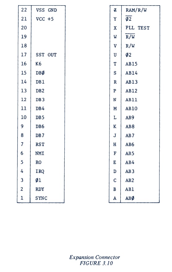
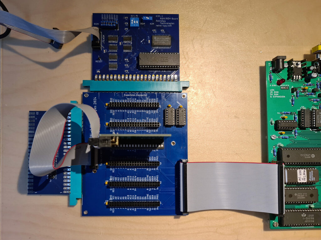
The IEC-floppy/RAM card is a card connected to the Extension connector of the KIM-1 (any KIM-1, original and replica).
post

KIM-1 I/O-Platine

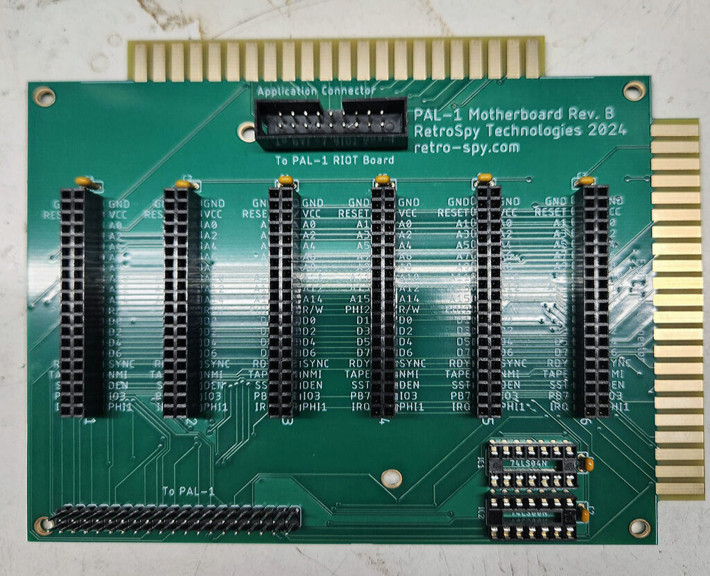
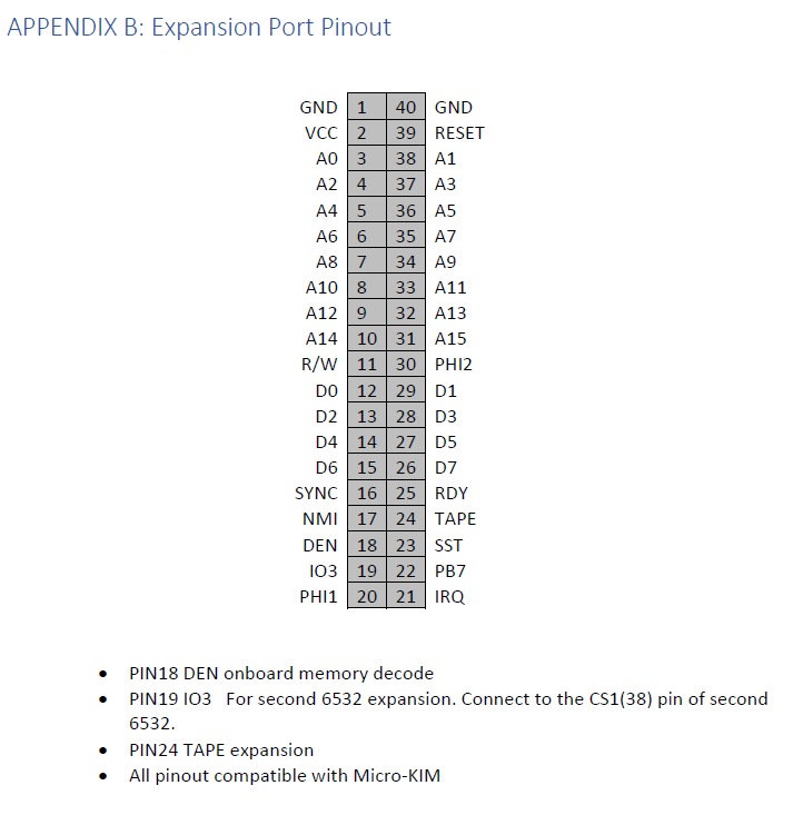
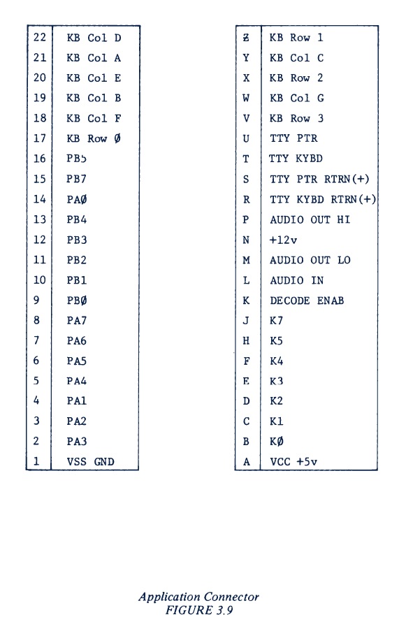
The I/O card has connectors for Power, audio in/output for data save and load, and a RS232 connector. All signals on the Application connector are made available on 2×22 pinheader.
To connect the IEC/RAM/ROM card there is a 2×5 pinheader.

Available downloads:

post

Nachbau KIM-1

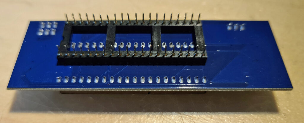
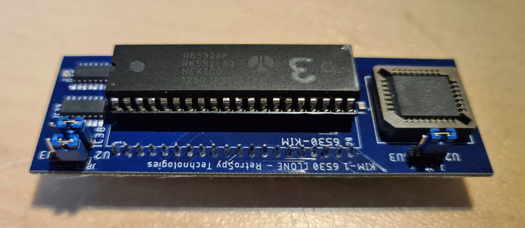
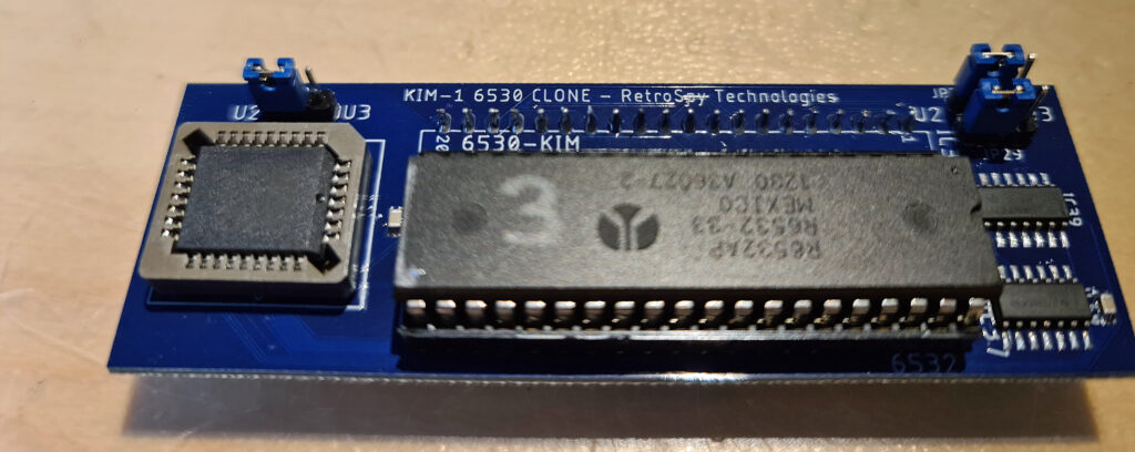
The replica is yet another implementation of the idea from my Dutch friend Ruud Baltissen: Build a KIM-1 with 6532s replacing the 6530-002/003.

What makes this replica special is:

    • It is a KIM-1, with everything the KIM-1 has: two 6532, audio, 1K RAM, 6530-002 and 6530-003 ROM, exactly the same logic for TTY and audio, application and extension connector.
    • The layout is in size and layout nearly equal to the KIM-1, it looks as close as possible as the original
    • The extra ROM is hidden on the back of the PCB
    • The PCB traces are not straight with sharp corners, but are bended like the hand layed out KIM-1 PCB

The keyboard is the best replica of the KIM-1 keyboard ever seen, see the KIM-1 replica keyboard page for details

Ralf made available the gerbers of the Nachbau KIM-1 PCB and wrote a (in German) construction guide.
Here are the available downloads:

KIM-1 Nachbau Circuit diagram

Bare PCBs (thanks Micha!), not the latest, but will give an operational KIM-1

post

Ruud Baltissen: Build a KIM-1

Ruud Baltissen started the whole KIM-1 Replica world by publishing a page many years ago about Building a KIM-1
All replica’s, from the MICROKIM to the Nachbau followed his design.

Replicated here the are relevant text and schematics by Ruud.

Build a KIM-1

The goal of this project is to rebuild the KIM-1. This isn’t “Just take the schematic of the KIM and go ahead!”. The KIM-1 uses two 6530s that are custom ICs and therefore cannot be bought in any shop. This project uses replacement parts.
The troubleshooter: 6530
As said, the KIM-1 has two 6530s on board. For more info about this IC, please read about the 6530 here. Anybody who is a little bit familiar with the hardware market can tell you that you cannot buy the 6530 as a regular part. And the 6530 is a custom IC: Commodore made various types but all were branded 6530. For example, the 6530 found in the CBM 4040 drive is different from the ones of the KIM. Even the two 6530s of the KIM itself are different: in this case it is the content of the builtin ROM.
Happily enough there is another IC available that can be used as replacement: the 6532.

The 6532 has 16 I/O lines, an internal timer and 128 bytes of RAM onboard, but no ROM. For this project we’ll use an external EPROM as replacement. The pin out of the 6532 is completely different but that should not be a problem.
Another difference is that a 6532 has pin PB6 available where a 6530 hasn’t. See it as a bonus as I haven’t found any reason how it could jeopardize our project.
The 6530 can generate a IRQ but in case of the KIM-1 this feature isn’t used. The main reason is that pin PA7 is needed to output the signal and it is used for other things. The 6532 has a separate IRQ output. I used two jumpers, J54 and J5, to enable someone to use this function if needed.
The last and major difference however lays in the way the registers are selected:

function:       RS:  A6:  A5:  A4:  A3:  A2:  A1:  A0:  R/W: 
                                                            
RAM              0    x    x    x    x    x    x    x    x   
                                                            
DRA              1    x    x    x    x    0    0    0    x     A
DDRA             1    x    x    x    x    0    0    1    x     B
DRB              1    x    x    x    x    0    1    0    x     C
DDRB             1    x    x    x    x    0    1    1    x     D
                                                            
PA7, IRQ off,                                               
      neg edge   1    x    x    0    x    1    0    0    0     F
PA7, IRQ off,                                               
      pos edge   1    x    x    0    x    1    0    1    0     G
PA7, IRQ on,                                                
      neg edge   1    x    x    0    x    1    1    0    0     H
PA7, IRQ on,                                                
      pos edge   1    x    x    0    x    1    1    1    0     I
                                                            
read interrupt                                              
       flag      1    x    x    x    x    1    x    1    1     E
                                                            
read timer,                                                 
       IRQ off   1    x    x    x    0    1    x    0    1     J
read timer,                                                 
       IRQ on    1    x    x    x    1    1    x    0    1     K
                                                            
Clock / 1,                                                  
       IRQ off   1    x    x    1    0    1    0    0    0     L
Clock / 8,                                                  
       IRQ off   1    x    x    1    0    1    0    1    0     M
Clock / 64,                                                 
       IRQ off   1    x    x    1    0    1    1    0    0     N
Clock / 1024,                                               
       IRQ off   1    x    x    1    0    1    1    1    0     O
                                                            
Clock / 1,                                                  
       IRQ on    1    x    x    1    1    1    0    0    0     P
Clock / 8,                                                  
       IRQ on    1    x    x    1    1    1    0    1    0     R
Clock / 64,                                                 
       IRQ on    1    x    x    1    1    1    1    0    0     S
Clock / 1024,                                               
       IRQ on    1    x    x    1    1    1    1    1    0     T

In total 5 address lines are used, meaning 32 registers. But 11 of the 19 registers have one or more mirrors.

Read:          J E J E         K E K E         J E J E         K E K E 
Write:         F G H I         F G H I         L M N O         P R S T 
R/W:           A B C D         A B C D         A B C D         A B C D         

As we can see, the last 16 registers equal the 16 of the 6530 itself. So now we have to develop some logic which will do the following:

  • The I/O of the 6532 is only visible within a range of 64 bytes
  • The first 16 bytes represent register 16 to 31
  • The next 48 bytes are mirrors of the first 16
  • Only 64 bytes of RAM are used

Conclusion:

  • Input A6 won’t be used and can be tied to GND
  • Input A4 is connected to address line A4 of the 6502 via a NAND gate.
  • The second input of that NAND gate is connected to the /CS2 input.
    The idea behind this is simple: The moment that the I/O part of the 6532 is selected, the NAND gate outputs a (H) thus selecting the wanted last 16 registers. If needed, the user can select the other 16 registers as well by connecting the second input of the NAND gate to +5V.
  • A 74LS138 enables the /RS and /CS2 lines at the right moment.

ROM and RAM
Here we have a luxury problem. We only need 2K of (EP)ROM like the 2716. The problem is that the 2716 is hard to find and more expensive then the 2764 or its bigger brothers. When we use a bigger EPROM we could tie the unused address lines to GND.
The same problem occurs with the RAM. In this case I have chosen for a 62256, a 32 KB RAM. This looks like a massive overkill but see later.
If we have to use bigger RAMs or EPROMs anyway, it is quite easy to use other parts of that chip by OR wiring the CS line with more Kx outputs of the main 74145. In case of the EPROM we also can connect switches to the surplus address lines and have the advantage of a multi-KERNAL system.

Extra address range
KIM-1 only supported an address range of 8 KB in the first place. The pin DECEN at the Userport can be used to extend that range but HAS to be connected to GND for the original configuration. The idea is that external cards can use this input to alter the range.
I added an extra 74145, IC7, and two jumpers that enable the user to make a more efficient use of the hardware. Both jumpers, J2 and J3, have to be closed to start with.
If you don’t want to use the 74145 at all, only close jumper J1.

The first thing one can do is to let the binary start at address $F800. Your self built KIM will still behave as usual. Now you can add your own RAM from address $0000 on up to $E000 and the only thing you have to do is remove jumper J2.
If you are only interested in adding RAM, a better idea is to use the original one, IC4, the 62256 32 KB RAM. You only have to remove the jumpers J13..17 and to close one or more pair of pins of jumper block J18. By closing all four pair of pins you make use of the full 32 KB.
Jumper J3 is only needed if you want to expand your self built KIM even further and want to use, for example, the $E000/$FFFF range for (EP)ROM.

Schematics of the new KIM-1

What are the major differences with the original schematic?

  • Replacement of the 6530s by 6532s.
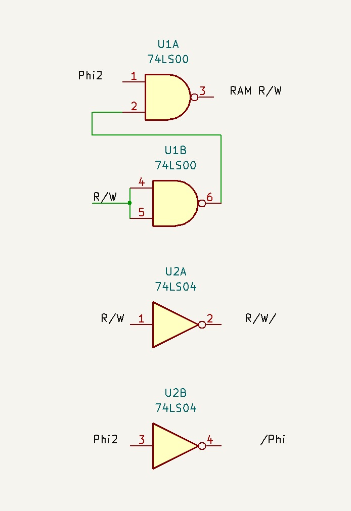
  • Addition of two NAND gates to handle the 6532s.
  • Addition of an EPROM.
  • Replacement of the 6108 RAM ICs by a 62256 or equivalent 32K*8 SRAM.
  • Addition of a 74LS138 to decode the RAM and I/O of the 6532s.
  • The resistor for K6 has been dropped.
  • Addition of jumpers to enable the combination of other K lines.
post

KIM-1 replica keyboard

Construction of a nearly exact KIM-1 replica keyboard.

Original version: Design, images and original text in German by Ralf (ralf02, forum64.de), from the KIM-1 Aufbau anleitung, and KIM-1 Keypad by user hackup, October 30, 2022 on thingiverse

Circuit diagram of the Keyboard PCB

For the keyboard construction you need the following parts:

  • 1 3D printed keyboard frame, STL from thingiverse
  • 2 keypads with 16 keys each as shown (actually, you just need 1 1/2)
  • 1 keypad PCB, see the gerber file
  • 1 SPDT slide switch, 2.54mm pitch
  • 1 female pinheader connector, 15 pins, preferably low profile
  • 1 male pinheader, 15 pins to match the female one
  • 6 self tapping screws, 2x6mm
  • labels printed white on black for the keys E, F, AD, DA, PC, +, GO, ST, RS
  • double sided adhesive tape to glue the clips to the motherboard

The keyboard PCB has to be gold plated (ENIG). With tin-plated PCBs the contact from the keys is not reliable.

Downloads made available by Ralf:

First dismantle the two keyboards and cut the two rubber contact mats as seen in the next picture. Keys 0-0 and A-D have the right lettering, make the other with a letter printer white on black.

Place the keycaps in the 3D printed case:

Now solder the slide switch and the pinheader on the PCB. Cut the rubber mat on the location of the slide swithc. Put the mat in the 3d printed case and fix with 6 screws:

Next place the four M3 screws in the holes in the PCB and the parts in the case. Now place the PCB on the 1 pin pinheader and fix the four screws with washers from the bottom.


The two reds are only for decoration, to make it look like as on the KIM-1.

Next photos credit to Bigby (of forum64.de):

post

Nachbau eines KIM-1

Ralf (Ralf02, forum64.de) started a thread on the forum64 called Instandsetzung und Nachbau eines Kim-1 in March 2022. 99 pages of designs and discussions and contributions by many in the thread delivered a working KIM-1 that is closer to the original KIM-1 than any KIM-1 replica designed. A great achievement and a well deserved compliment to Ralf and the thread authors!

The work of Ralf is not limited to the KIM-1 replica itself. He also designed a KIM I/O module and a 1541 IEC/RAM/ROM module.
Noteworthy is the replica of the KIM-1 keypad.

On the following pages these boards are introduced.

The most current version of the ‘Nachbau’ is on the formu64.de thread.

KIM-1 Replika

Colin Wolf (C. W. (chefkoch) ) posted a thread in 2021 on mikrocontroller.net showing a KIM-1 Replika he had build.
A KIM-1 with the dimensions and layout of the original KIM-1! OF course he used 6532 instead of the 6530-002 and -003, so a ROM was needed. To preserve the layout, this ROM was hidden as daughterboard on the back. The daughterboard also has the extra decoding circuit required for the 6532s. A very elegant solution!

The text by Colin on the post:
Hallo *,

wie bereits in dem Thread Beitrag “Fotos KIM-1 rev. F oder G”
angekündigt war ich dabei einen KIM-1 nachzubauen. Nach einigen
lehrreichen Stunden CAD-Fleißarbeit ist es nun vollbracht.

Es lebt!

Die beiden 6530 wurden durch 6532 ersetzt. Für die Umkodierung wurde der
Vorschlag unter
http://retro.hansotten.nl/6502-sbc/6530-6532/kim-1-6530-replacement/
benutzt und als Huckepackplatine realisiert. Der komplette
Funktionsumfang mit Audio- und Fernschreiberinterface ist also
vorhanden.

I have received the circuit diagrams in PDF format and publish here with permission by Colin Wolf:
KIM-1 Circuit diagram
Daugther board

He showed these photos on the post:


Wolfgang Robel build a KIM-1 Replika with PCBs from Coloin Wolf. On his website he shows the build process and the working end result.

Photos reproduced here with permission from Wolfgang Robel. As you can see the end result is great, though he had to deal with broken 6532s from China and broken 2102 SRAM ICs.


KIM-1 Nachbau

On the forum Mikrocontroller.net I found a thread dedicated to a KIM-1 replica with a twist.
Author is Manfred Langemann (manni), this page is published with his permission.
Read here about the KIM computer which has the following features:

  • A complete 6502 Integrated Development Environment (IDE) for writing assembler source code, including editor, assembler, debugger and EEPROM programmer, see screenshot above.
  • The hardware comes with a 6502 micro-controller, 8 KByte EEPROM, 32 KByte RAM and an I/O interface based on an Intel 8255 PPI (Programmable Peripheral Interface), offering three 8-bit ports. The audio tape interface is realised by an NE565 PLL and the RS232 serial interface is based on a MAX232 IC