In 1982 I wrote/composed a program to have disassembled code on paper, with page numbers.
The core routine of the disassembler is the well-known Steve Wozniak/Allen Baum 1976 article A 6502 Disassembler from Apple
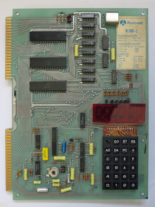
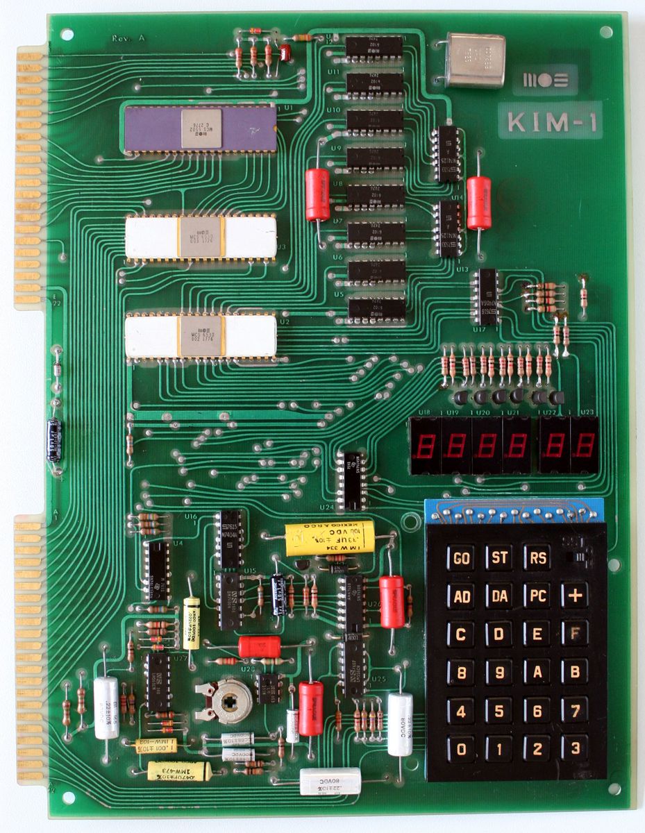
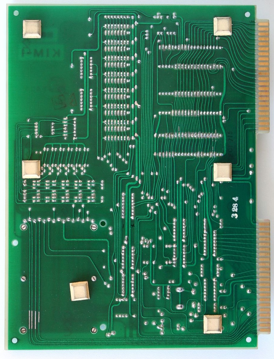
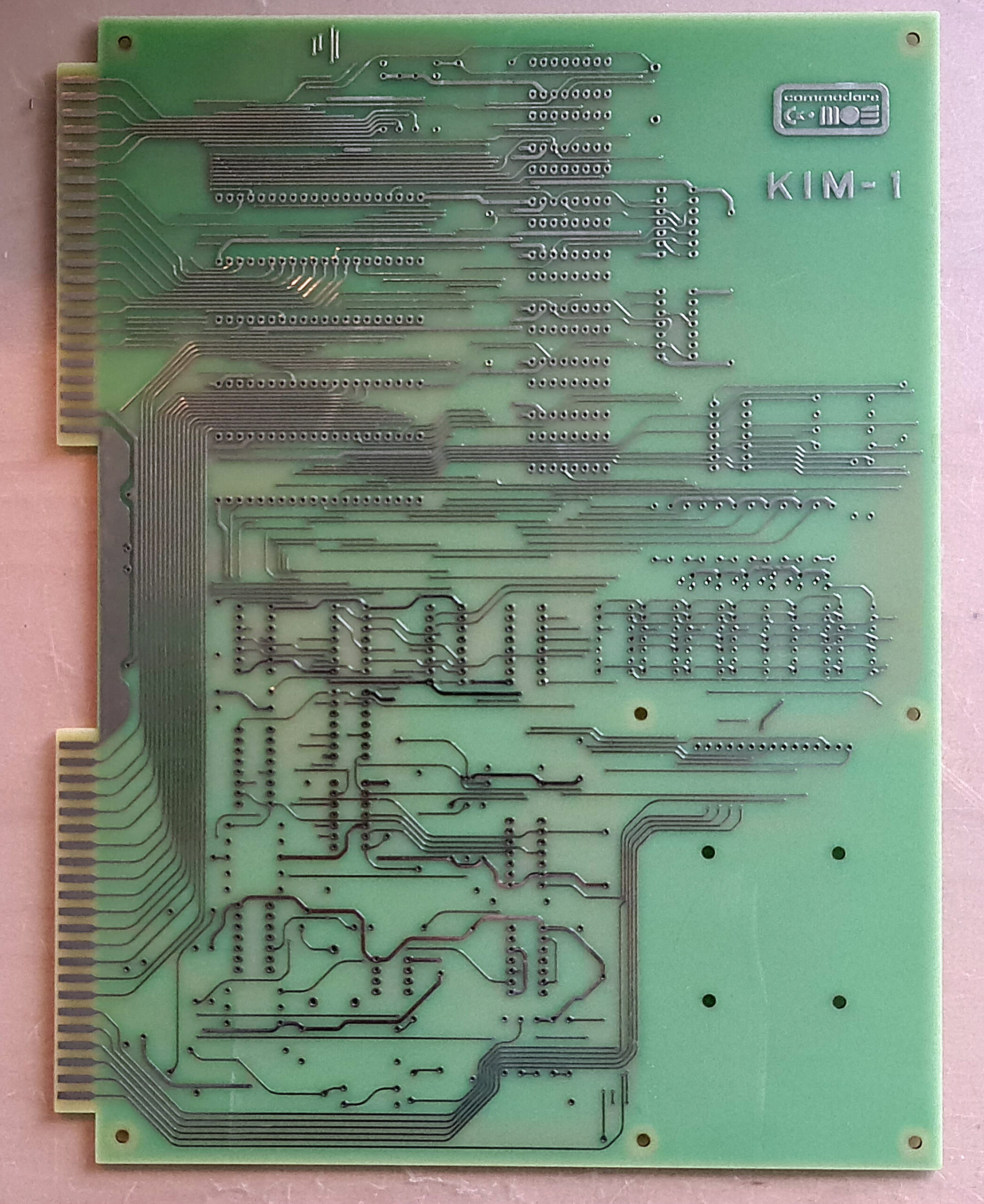
The program is a TTY program. I build it with the then current hardware and software of my KIM-1:
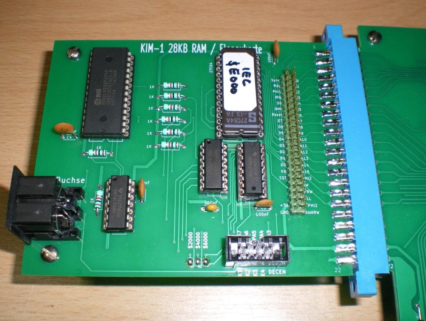
- 32K RAM from $2000
- Video terminal uppercase 24×32 on the KIM TTY serial in/output
- A parallel ASCII keyboard connected to the second 6532 RIOT port
- A serial connected, at 9600 baud, Heathkit H14 matrix printer
- Dual audio cassette records under motor control
- MICRO ADE assembler/Editor, extended and with video TTY as output, parallel keyboard as input and could print at the H14 printer
Only the KIM-1 survived today this setup and is now on display above my desk in an acryl case. Most of the software is converted from tape and is on this site in the KIM Software page.
The program was written to have a disassembled printed listing of software like the Microsoft Basic KB9 and other binary only software, so I could analyze, make notes and patch it at will to my hardware and more. It was located at location $B000, out of the way of where most programs were loaded, like $0400 or $2000.
The program prompts for output to video or to video + printer. If printer is selected the output will be paginated with page numbers and it asks for a header text.
I still have the printed output of Microsoft Basic with my hand written notes on it.
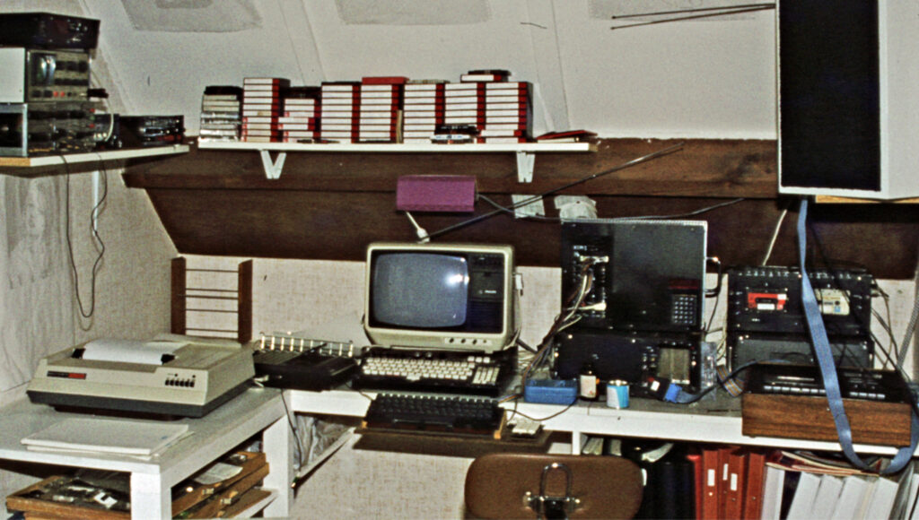
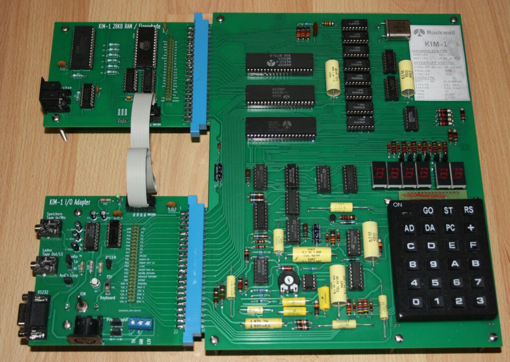
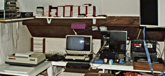
My workplace setup in 1982: KIM-1, dual cassette, tv monitor, H14 printer, ASCII keyboard
The original source and binary (restored from cassette, the previous version on the website was incomplete):
Printing disassembler, load and start address is $B000
Source of disassembler
Requires a parallel keyboard for character input at the free 6530 PIA port. H14 printer output if print is requested.
As is not fit for a standard KIM-1!
PRDIS Version 2
In January 2023 Glen Deas, K5GED, approached me about this program. He found out the binary was missing the last bytes (now corrected). He also showed me how he converted the MICRO ADE source to AS65 format and made it use the KIM-1 standard TTY I/O again.
Printing disassembler, load and start address is $B000 for KIM-1, Glen Deas version
   ; VERSION 1.1 JANUARY 2023  SYNTAX MODIFIED FOR THE
   ;  A65 CROSS ASSEMBLER   GLEN DEAS, K5GED  USA
       INVOKE A65:  A65 -L -M -H D6502TTYV2.S
   ; Version 2.0  MODIFIED TO USE THE KIM-1 SERIAL I/O INSTEAD OF PARALLEL KEYBOARD
   ;               USING KIM'S TTY ROUTINES - BY DEFAULT IT OUTPUTS TO THE VIDEO
   ;               MONITOR/TTY VIA THE OUTCHK CALL TO THE KIM-1 MONITOR
   ; Set up Procomm up for 7 data, Mark parity, and 2 stop bits, no echo
PRDIS Version 3
I could not resist to spent an afternoon on the source Glen Deas has given me. So much fun to work on code 40 years later. Grateful to Glen for his work on his vesion.
Here is my latest version, running fine in the KIM-1 Simulator.
Source and binary in papertape format V3 of PRDIS
Improvements in V3:
- No problems with echo or 7 bit anymore, all standard KIM-1 monitor
- Lowercase messages
- Code for H14 printer or parallel keyboard commented out, reducing size
- Rommable, variables moved to RAM $0200, program at $B000
- Stops output after every 16 lines, any key but Enter stops program
- Source formatted and syntax for TASM32, license added
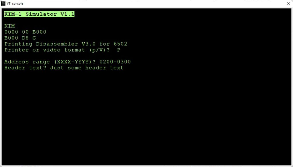
Example session, PRDIS disassembling itself without and with Pagination:
KIM
B000 D8 G
Printing Disassembler V3.0 for 6502
Printer or video format (p/V)?

Address range (XXXX-YYYY)? B000-B100
Disassembly:
B000  D8          CLD
B001  A2 FF       LDX #$FF
B003  9A          TXS
B004  A9 01       LDA #$01
B006  8D 00 02    STA $0200
B009  A9 00       LDA #$00
B00B  85 EE       STA $EE
  .
  .
  .
B0F6  C9 22       CMP #$22
B0F8  F0 13       BEQ $B10D
B0FA  29 07       AND #$07
B0FC  09 80       ORA #$80
B0FE  4A          LSR
B0FF  AA          TAX

KIM
B000 D8 G
Printing Disassembler V3.0 for 6502
Printer or video format (p/V)?  P

Address range (XXXX-YYYY)? B000-B200
Header text? PRINTING DISASSEMBLER

PRINTING DISASSEMBLER                                             Page 01

B000  D8          CLD
B001  A2 FF       LDX #$FF
B003  9A          TXS
B004  A9 01       LDA #$01
B006  8D 00 02    STA $0200
B009  A9 00       LDA #$00
B00B  85 EE       STA $EE
B00D  8D 01 02    STA $0201
B010  20 2A B3    JSR $B32A
B013  A2 B4       LDX #$B4
B015  A0 AC       LDY #$AC
  .
  .
  .
B1C6  60          RTS
B1C7  A5 F0       LDA $F0
B1C9  38          SEC

PRINTING DISASMBLER                                             Page 05

B1CA  A4 FB       LDY $FB
B1CC  AA          TAX
B1CD  10 01       BPL $B1D0
B1CF  88          DEY
  .
  .
  .
B1F9  33          ???
B1FA  D0 8C       BNE $B188
B1FC  44          ???
B1FD  00          BRK
B1FE  11 22       ORA ($22),Y

KIM
B000 D8