VKIM is a KIM-1 emulator written for the Palm OS.
A Basic KIM-1 is emulated. With tape I/O, program load or save. Source included.
I do not own a Palm. But a PALM can be emulated. An excellent browser based one is CloudPilot .
You need a Palm OS ROM and VKIM. I packed PALM OS 5 ROM and the application VKIM in this archive.
The vKIM program emulates a M6502 processor with approximately the resources of a KIM-1: it has a keypad and display, 4 Kb of RAM (the standard KIM-1 had 1 Kb), 2 Kb of ROM containing a patched version of the ROM on a KIM-1 (more on that in a bit), 128 bytes of RAM at $1780-$17FF, and a simulated TTY. The I/O and timer resources of the two 6530 support chips are not emulated.
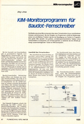
The interface that is implemented on the keypad is identical to the actual KIM-1 interface — because it is implemented by the KIM-1 software.
As a convenience the NMI vector at $17FA-$17FB and the IRQ vector at $17FE-$17FF are automatically set to $1C00 when vKIM is initially started, and when the “Clear all RAM” menu option is selected.
Emulated RAM is cleared only by explicit action — when vKIM is exited all RAM is saved, and restored when vKIM is restarted.
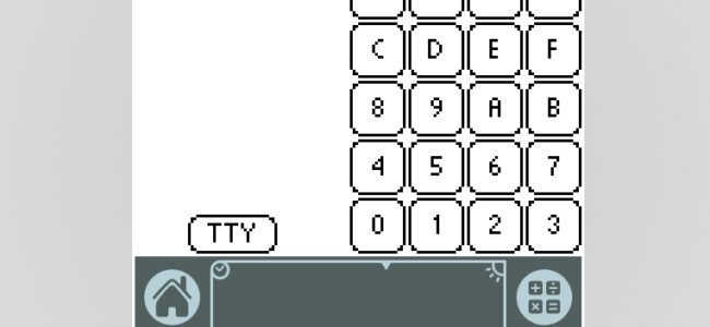
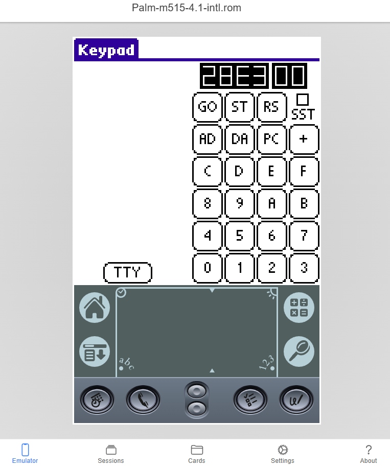
THE KEYPAD INTERFACE
The standard KIM-1 keypad is the interface that vKIM displays when started up. Since the use of this keypad is entirely a matter for the KIM-1 documentation, I will mention only the differences here. First, the SST switch has been replaced with a checkbox. When checked, SST mode is active; unchecking the box is equivalent to turning the SST switch to the “off” position. Further, as a convenience the locations $00EF-$00F5 are fomratted and displayed to the left of the keypad when SST mode is active.
Finally, there is a button labelled “TTY”. When this button is pressed, the keypad disappears and the TTY interface is displayed.
TTY INTERFACE
When TTY mode is selected (by pressing the “TTY” button on the keypad screen) a “TTY” emulator is displayed. This display includes “CR”, “LF”, and “Rubout” buttons, since these are not readily available through Graffiti input. All other input, however, is to be entered in the Graffiti area. As a convenience to the user (and to emulate the limitations of a real TTY) lower-case alpha input is translated to upper-case before being sent to the emulated KIM-1. As a result, it is not possible in the current version of vKIM to enter lower-case data to the emulated KIM-1. Feedback on whether this is a hardship will be taken into account for future releases.
Also, as a convenience a Rubout character is automatically generated when entering TTY mode. Thus, the “KIM” prompt will appear as soon as TTY mode is entered, without requiring the user to press “Rubout” first (as on a real KIM-1).
Finally, there is a button labelled “Keypad” which will return the program to the keypad interface.
THE MENU
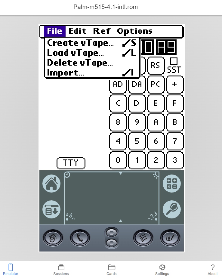
Under the “File” menu (press the Keypad label e.g.) are:
* “Create vTape…”
Saves which saves a copy of a specified range of addresses to a simulated or “virtual” tape;
* “Load vTape…”
Restores saved data from a vTape back into RAM (at the same location it was saved from);
* “Delete vTape”
Deletes a saved vTape;
* “Import…”
Loads data into RAM from a Memo Pad entry. The memo bust begin with “; vKIM”, and be followed by data in either dump format, or the paper tape format described in Appendix F of the KIM-1 User Manual. (Samples of both formats are shown below.)
Under the “Edit” menu are:
* “Copy block…”
Copies a block of data from one location in memory to another (no special provision is made for overlapping source and destination);
* “Clear block…”
Sets a specified range of addresses to $00;
* “Clear all RAM”
Sets all of RAM (including the block at $1780-$17FF) to $00, except for the IRQ and NMI vectors, which are set to $1C00;
* “Restart”
Emulates a processor restart.
Under “Ref”
* “Locations”
Lists system-use locations in page zero.
Under “Options”
* “Preferences”
Does nothing. Essentially a placeholder for options that may be implemented in the future.
* “About vKIM”
Gives information about the version of vKIM, and distribution information.
Import formats
Sample of of a memo pad item in “dump format”:
;vKIM BAGELS from First Book of KIM
0200 E6 16 20 40 1F D0 F9 D8 A9 0A 85 18 A9 03 85 10
0210 38 A5 13 65 16 65 17 85 12 A2 04 B5 12 95 13 CA
0220 10 F9 A6 10 A0 C0 84 11 A0 06 C5 11 90 02 E5 11
0230 46 11 88 D0 F5 18 69 0A 95 00 C6 10 10 D2 C6 18
0240 30 7A A9 00 A2 0C 95 04 CA 10 FB 20 CE 02 F0 FB
0250 20 CE 02 F0 F6 A5 08 F0 08 29 60 49 60 F0 A9 D0
0260 DD 20 6A 1F C9 10 B0 E3 C9 0A 90 DF A8 A6 10 E6
0270 10 B9 E7 1F 95 04 98 D5 00 D0 03 E6 0E 8A 95 0A
0280 A5 07 F0 31 A0 03 B9 0A 00 29 18 F0 12 B9 00 00
0290 A2 03 D5 0A F0 05 CA 10 F9 30 04 E6 0F 16 0A 88
02A0 10 E4 A2 01 B4 0E B9 E7 1F 95 08 CA 10 F6 20 CE
02B0 02 E6 0F D0 F9 20 CE 02 D0 FB F0 8F A2 03 B4 00
02C0 B9 E7 1F 95 04 CA 10 F6 A9 E3 85 08 D0 E0 A0 13
02D0 A2 05 A9 7F 8D 41 17 B5 04 8C 42 17 8D 40 17 E6
02E0 11 EA EA 88 88 CA 10 EF 20 40 1F 60
Sample of of a memo pad item in “paper tape format”:
;vKIM sample ptape format
;180000ffeeddccbbaa0099887766554433221122334455667788990afc
;0000010001
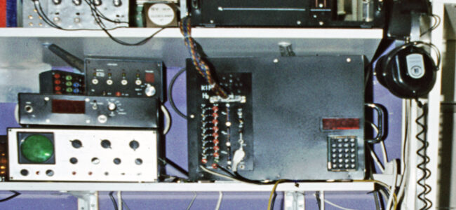
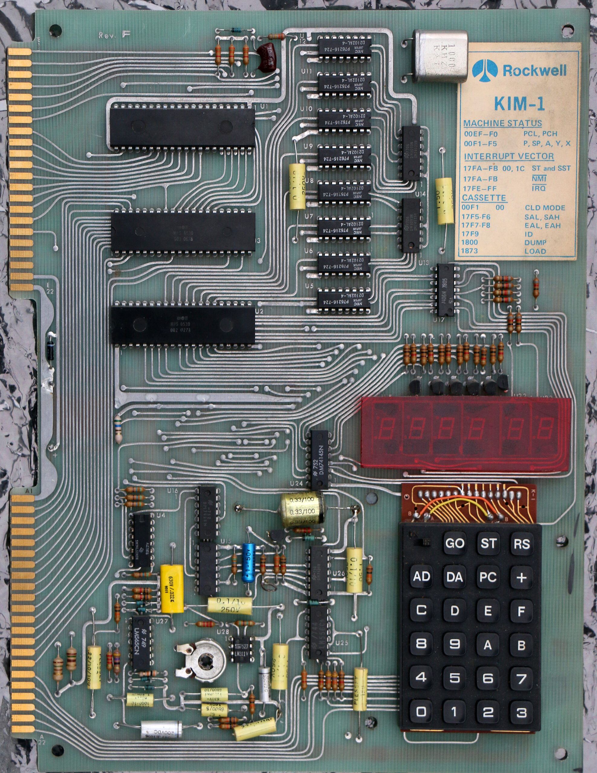
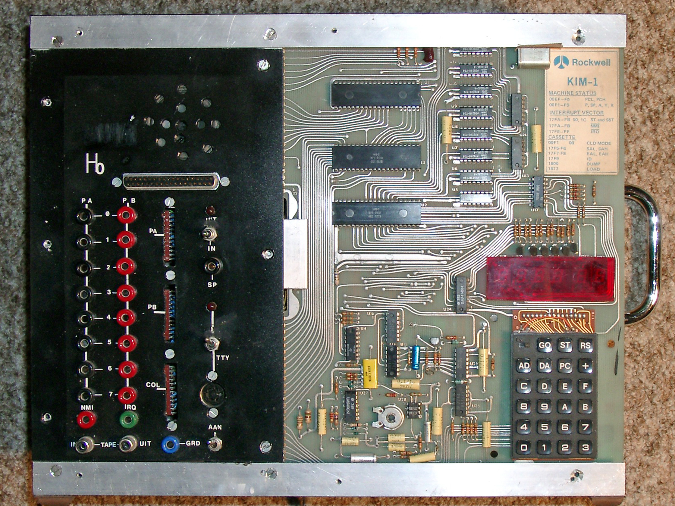
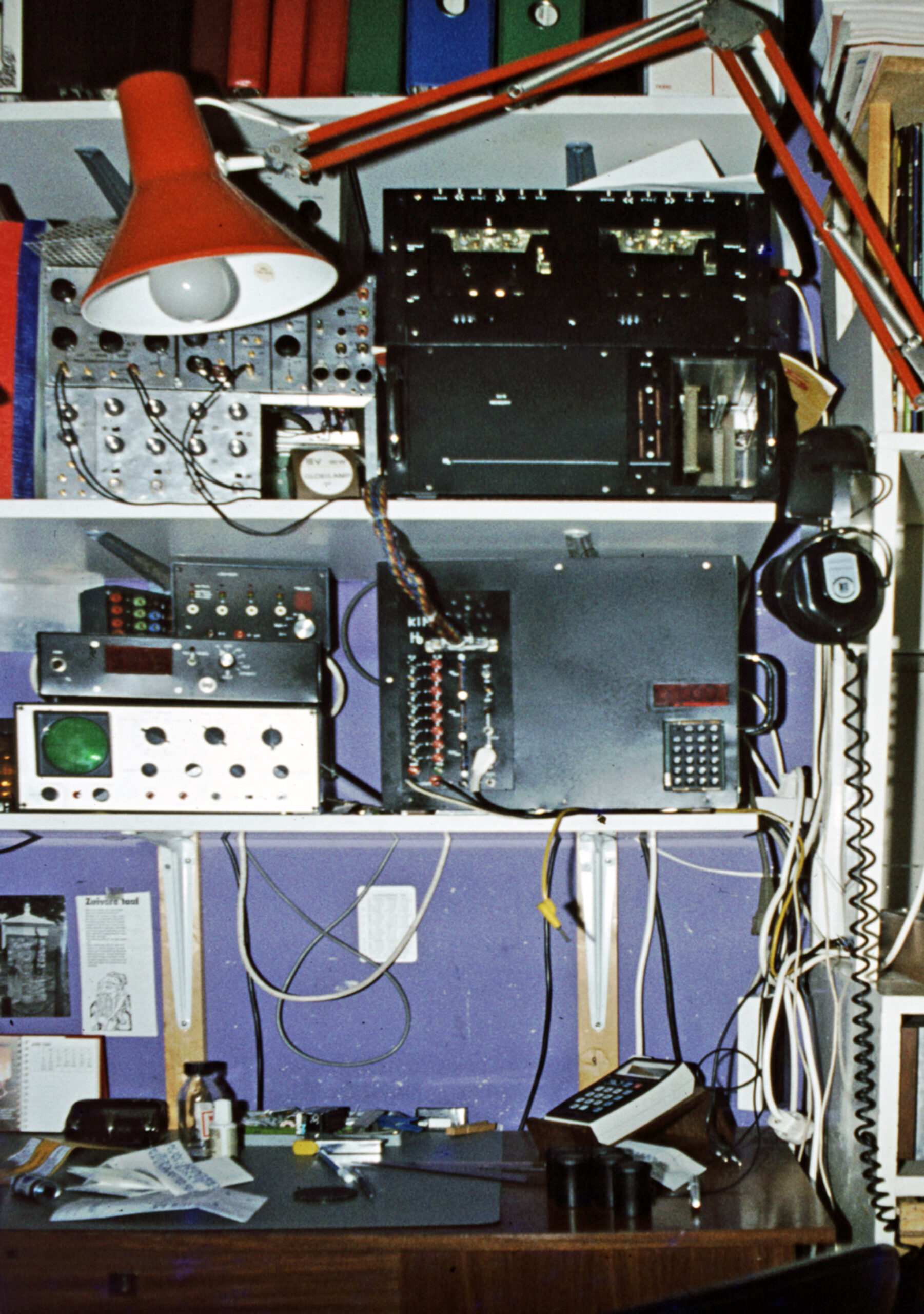
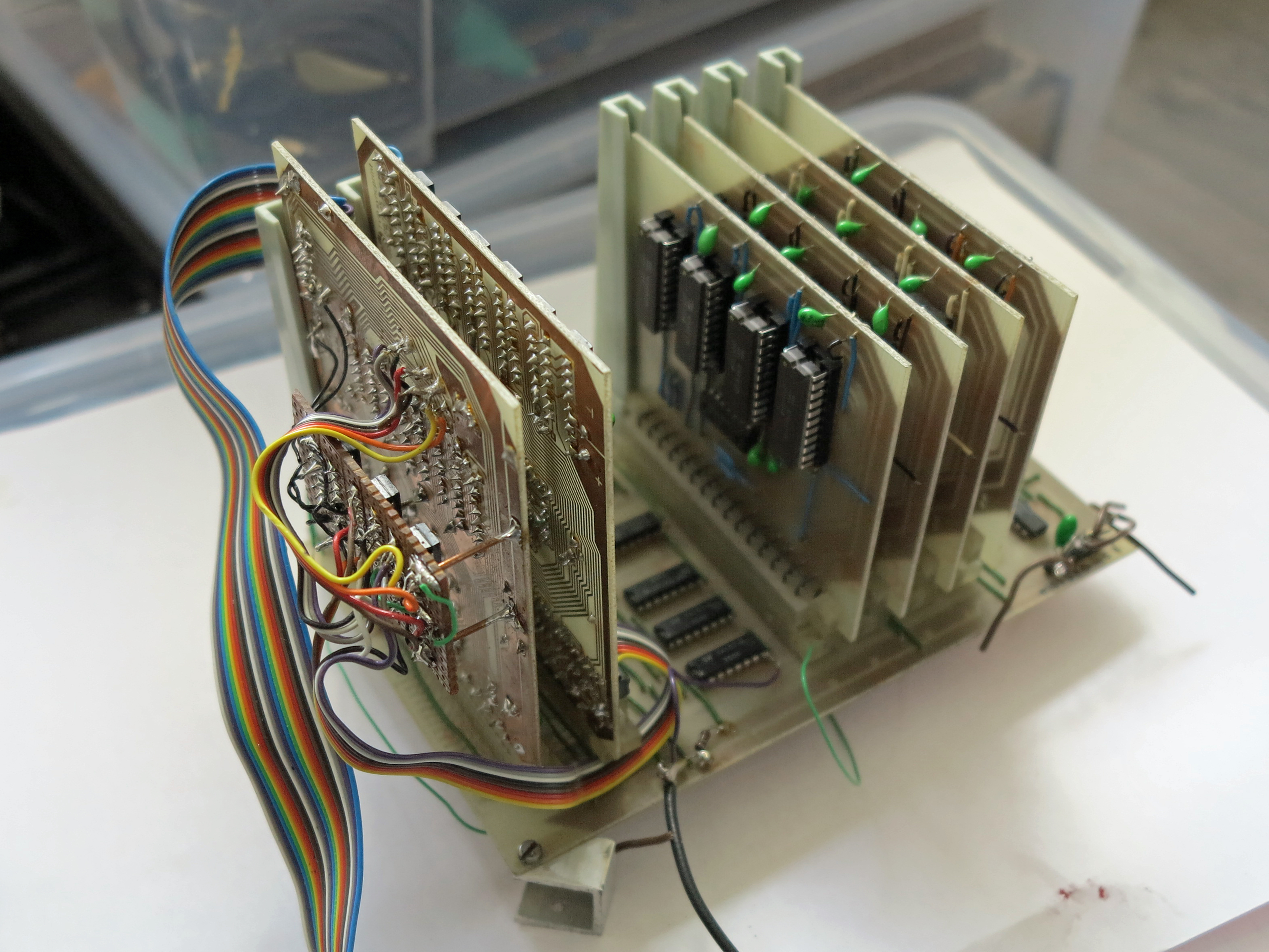
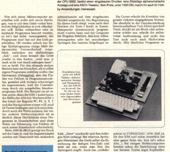
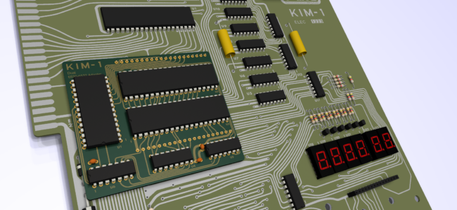
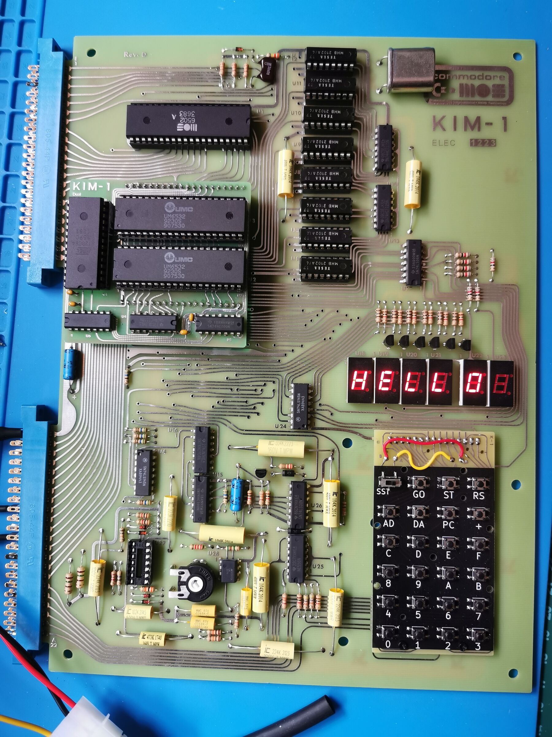
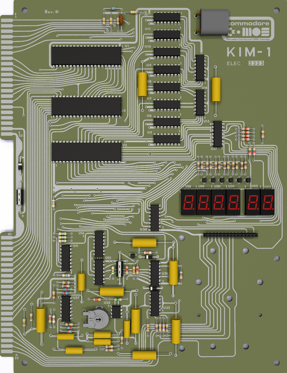
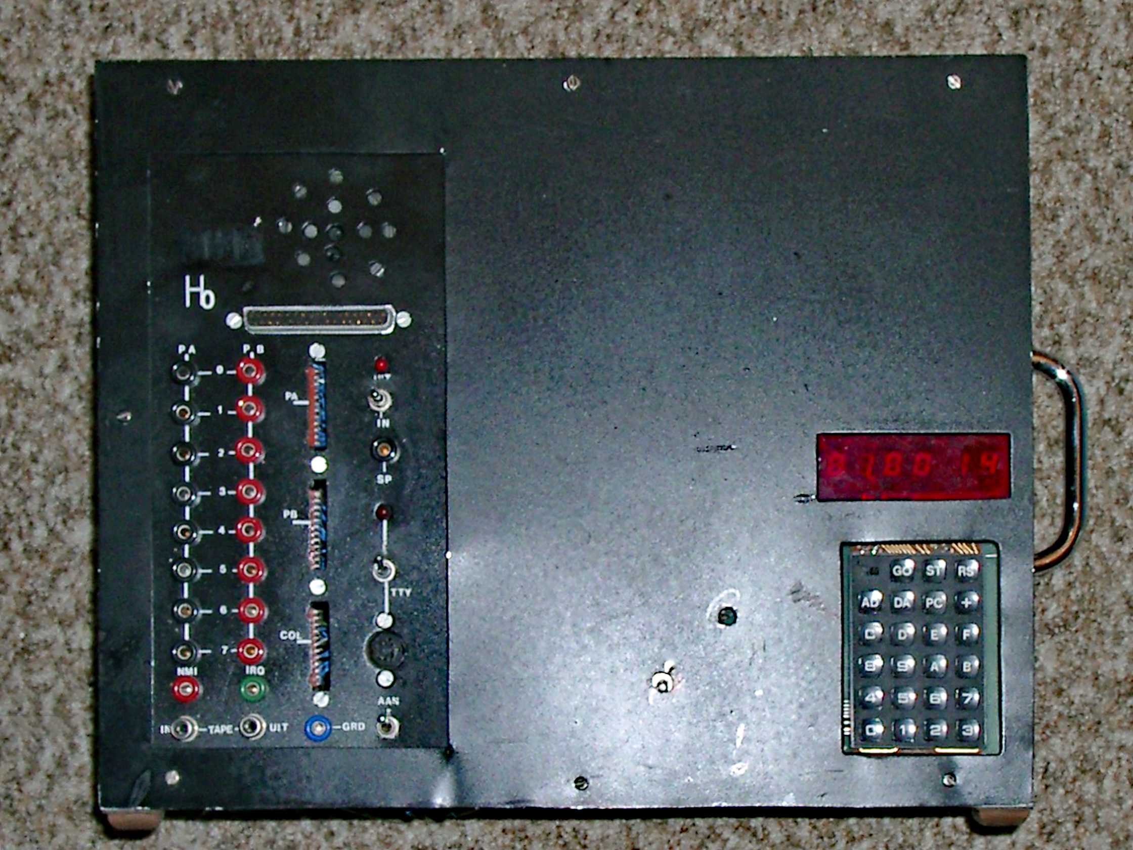
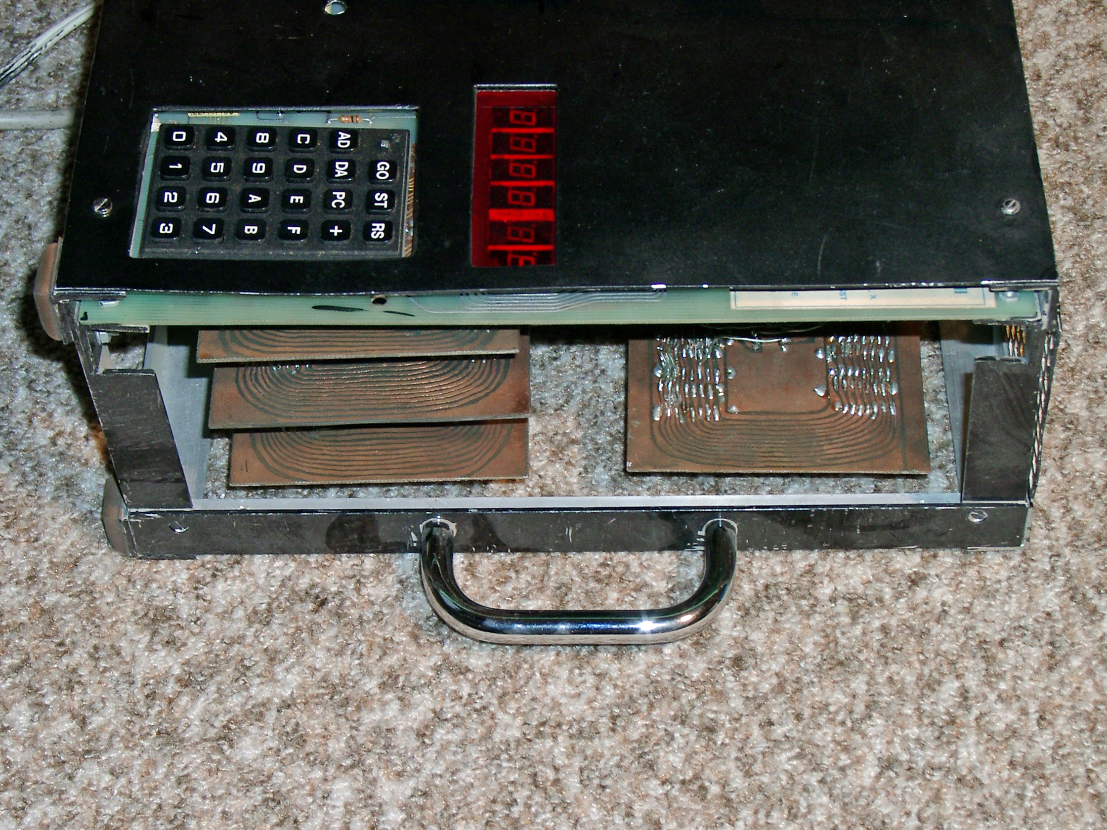
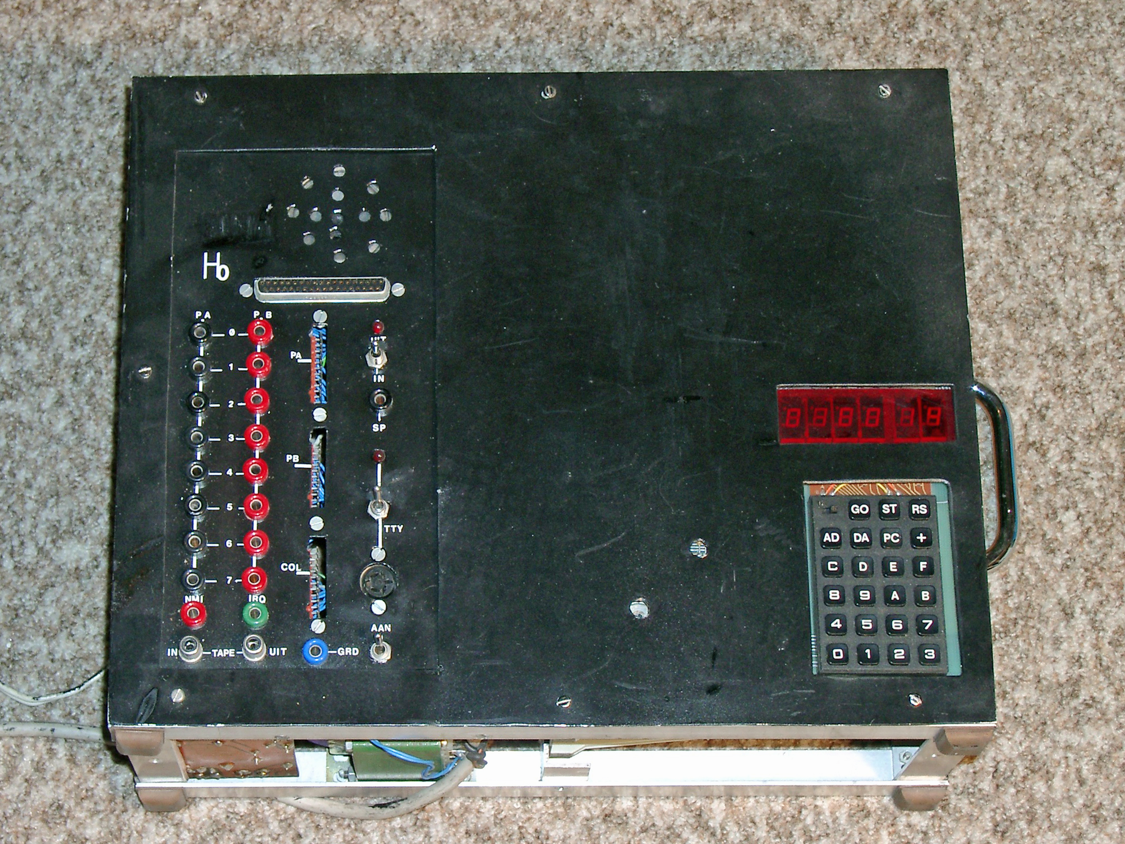
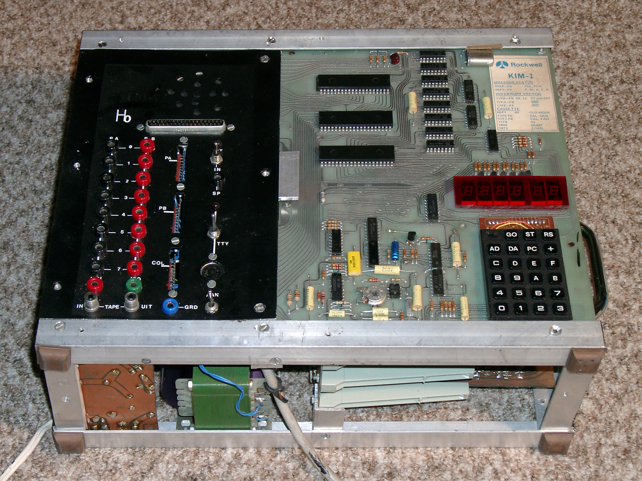
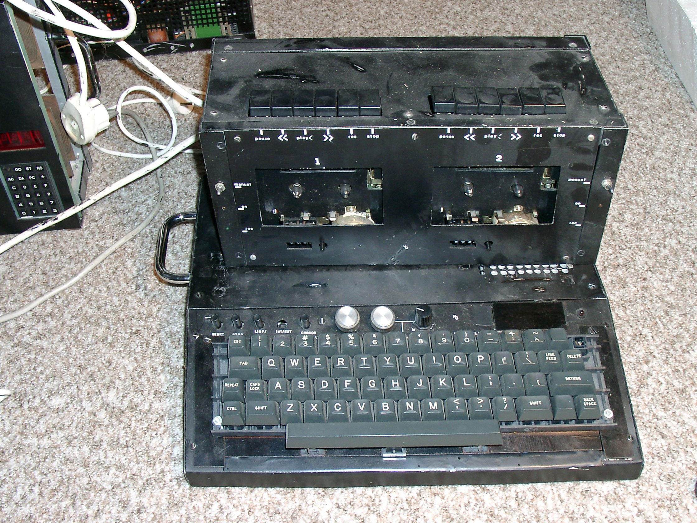
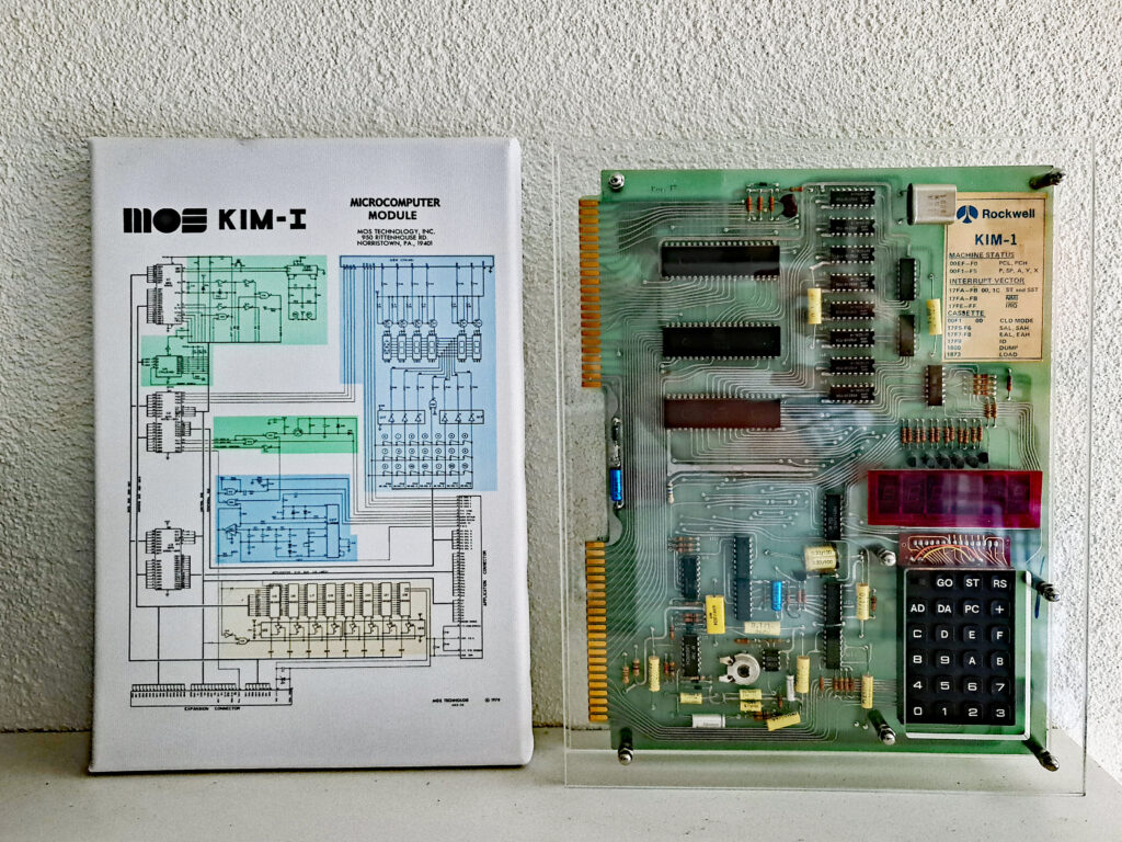 First the KIM-1, I still have it, in working condition, in my private museum. Changes still visible, a red acryl cover over the LED displays, a capacitor moved to the back to make it flat enough to fit the case I made and some supports to have it lay stable and safe on a table.
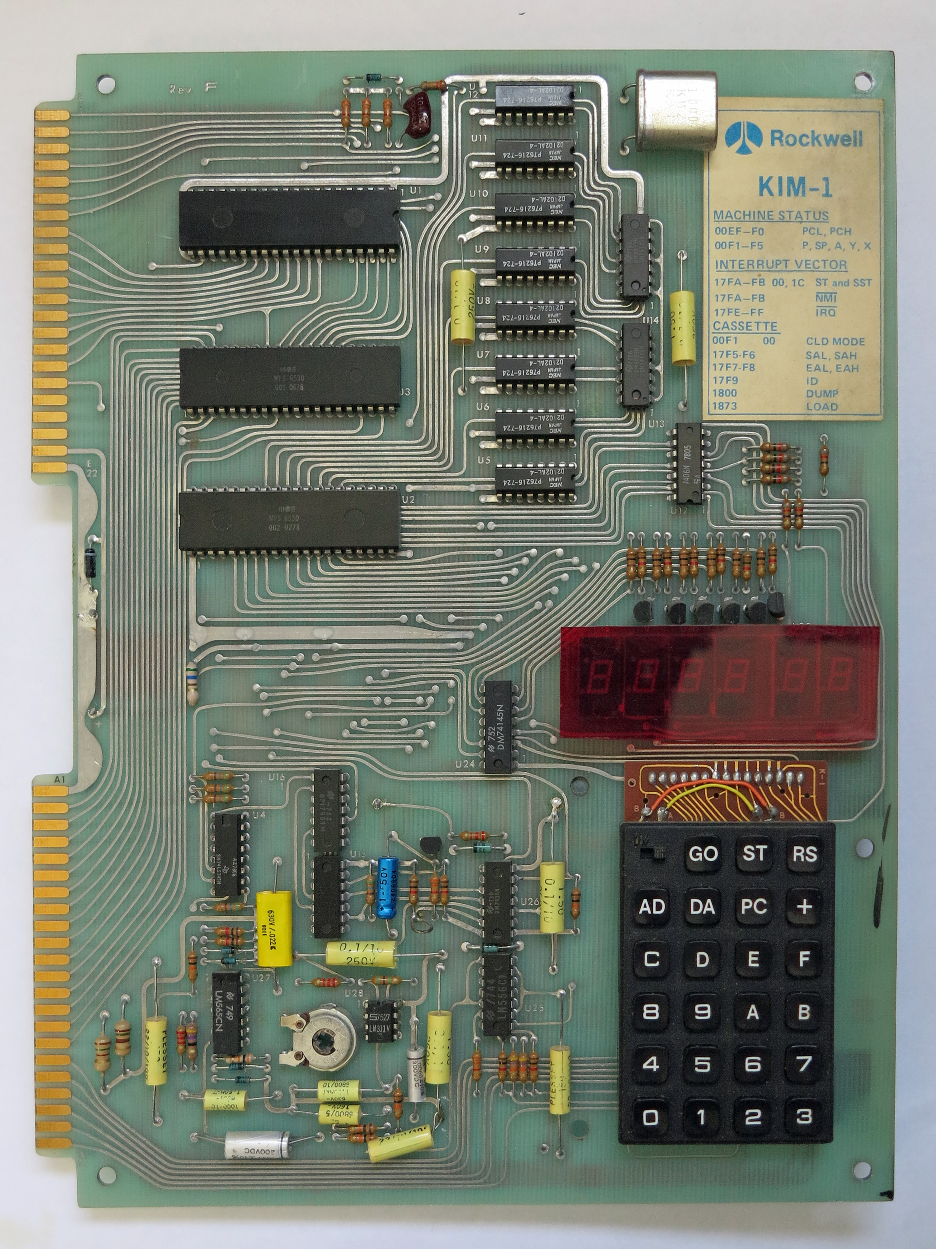


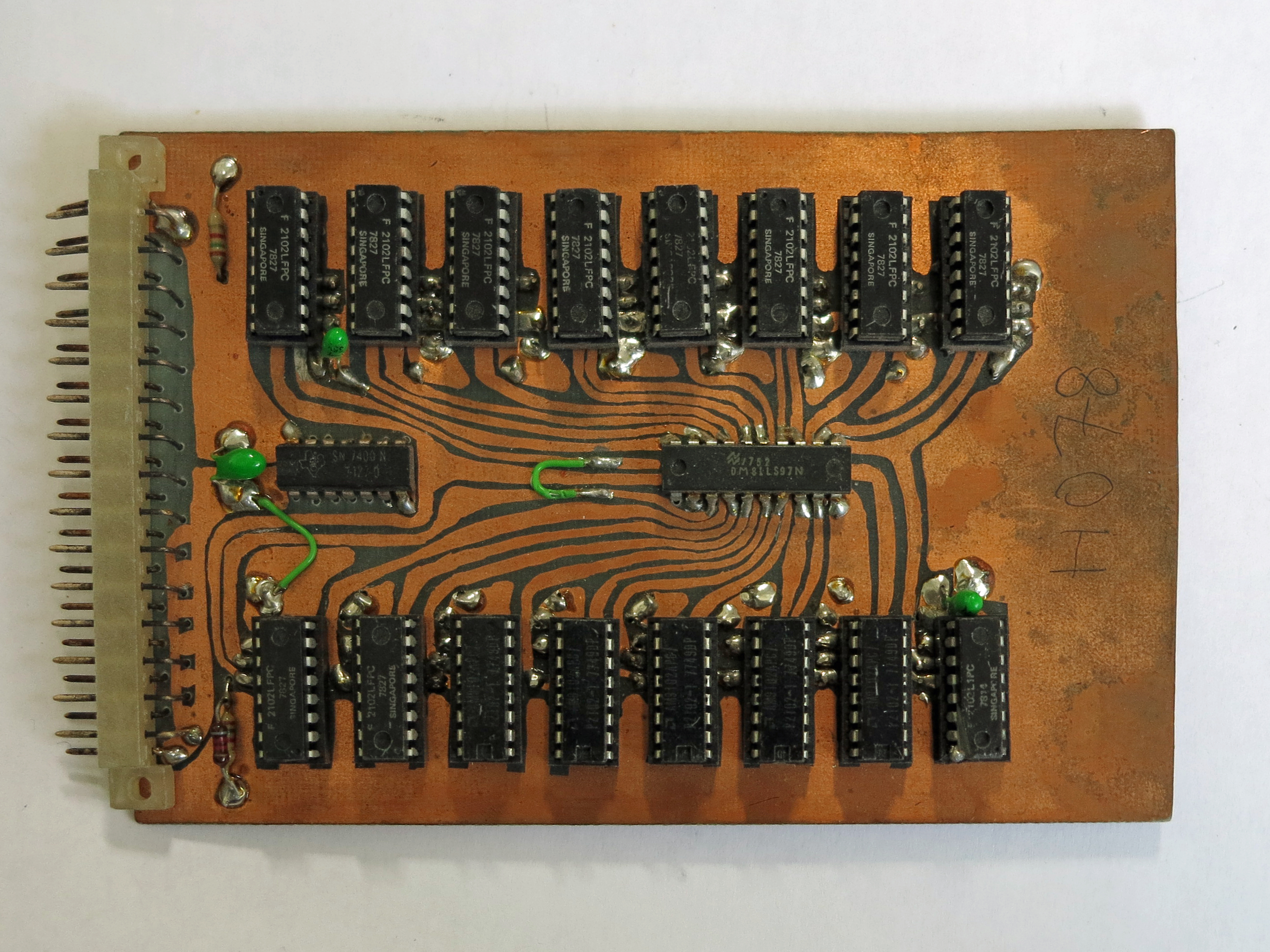
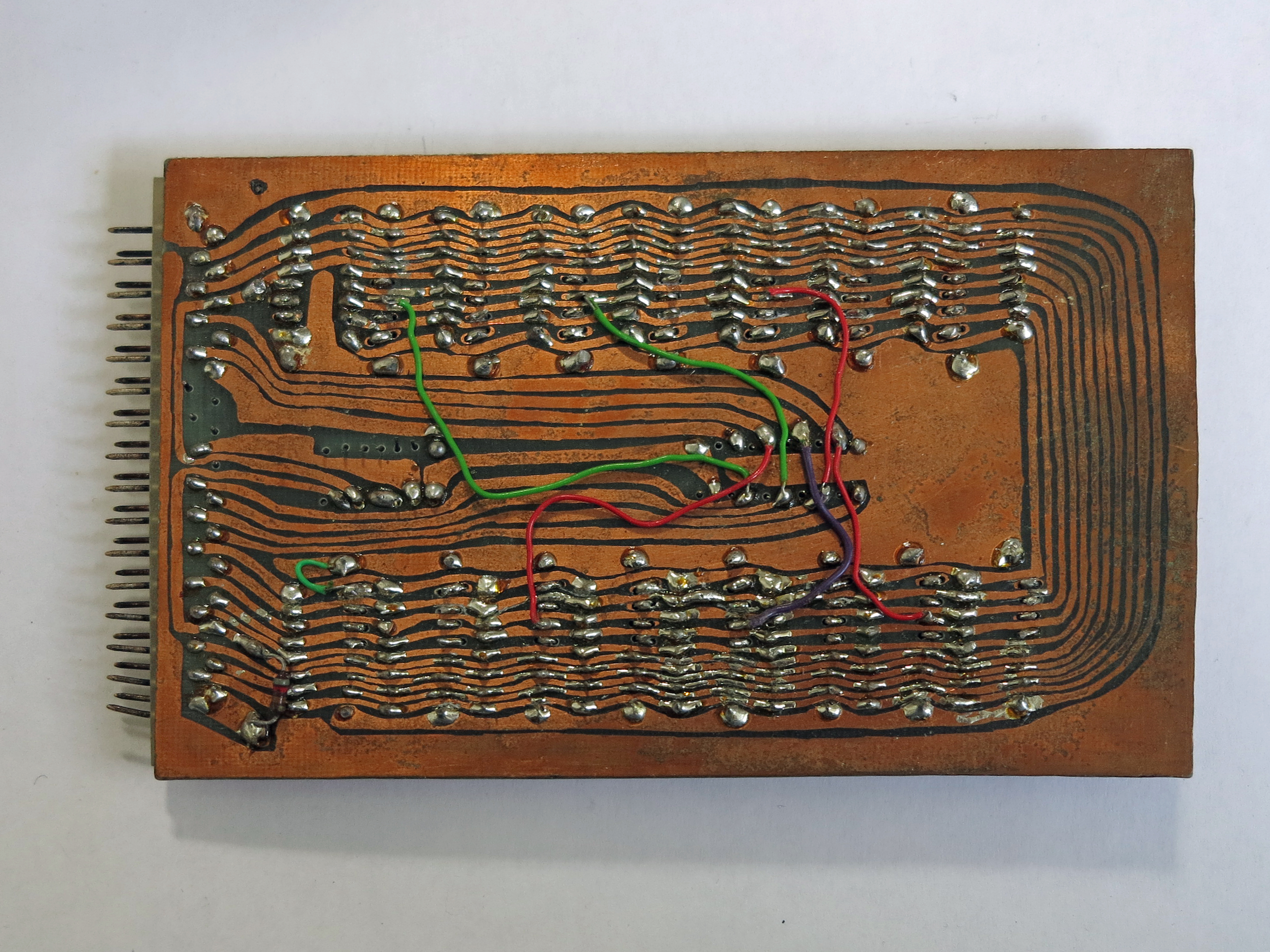
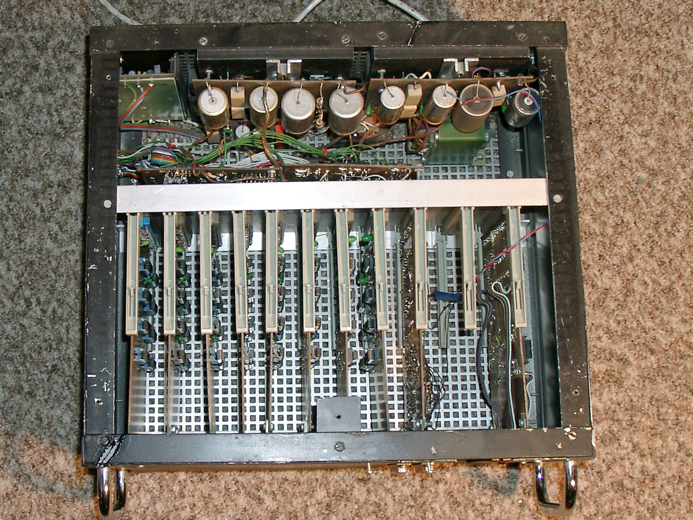

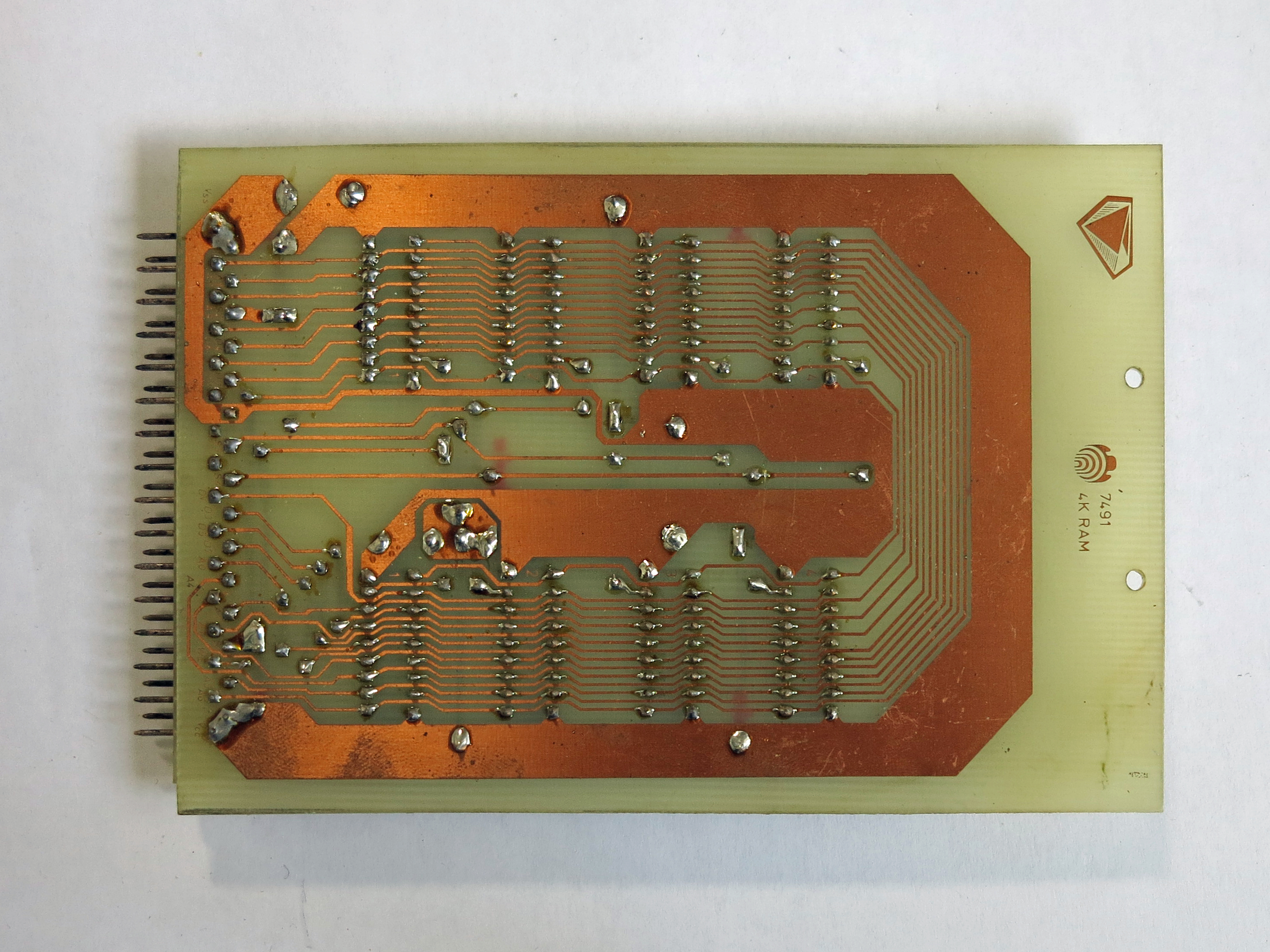
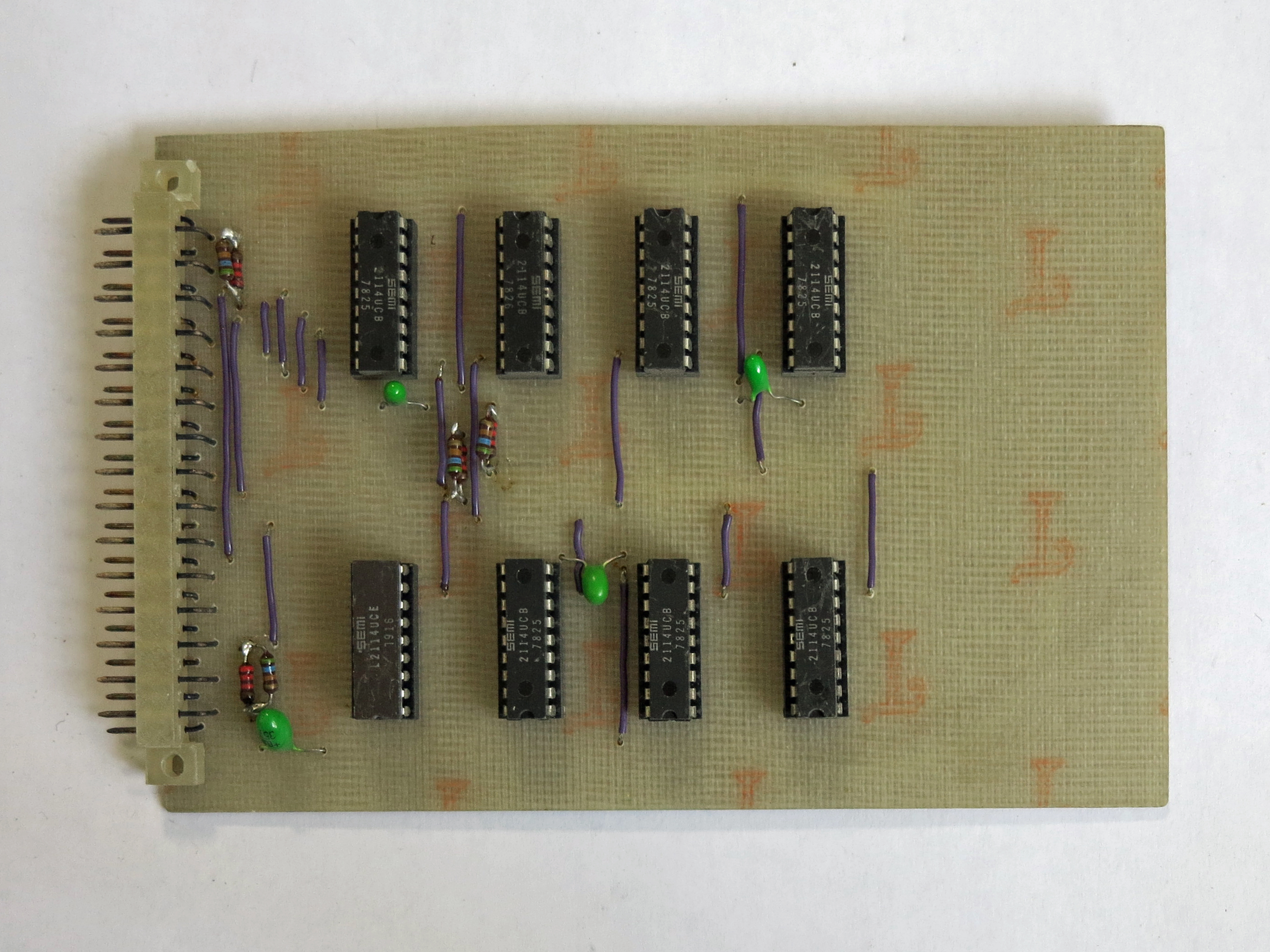
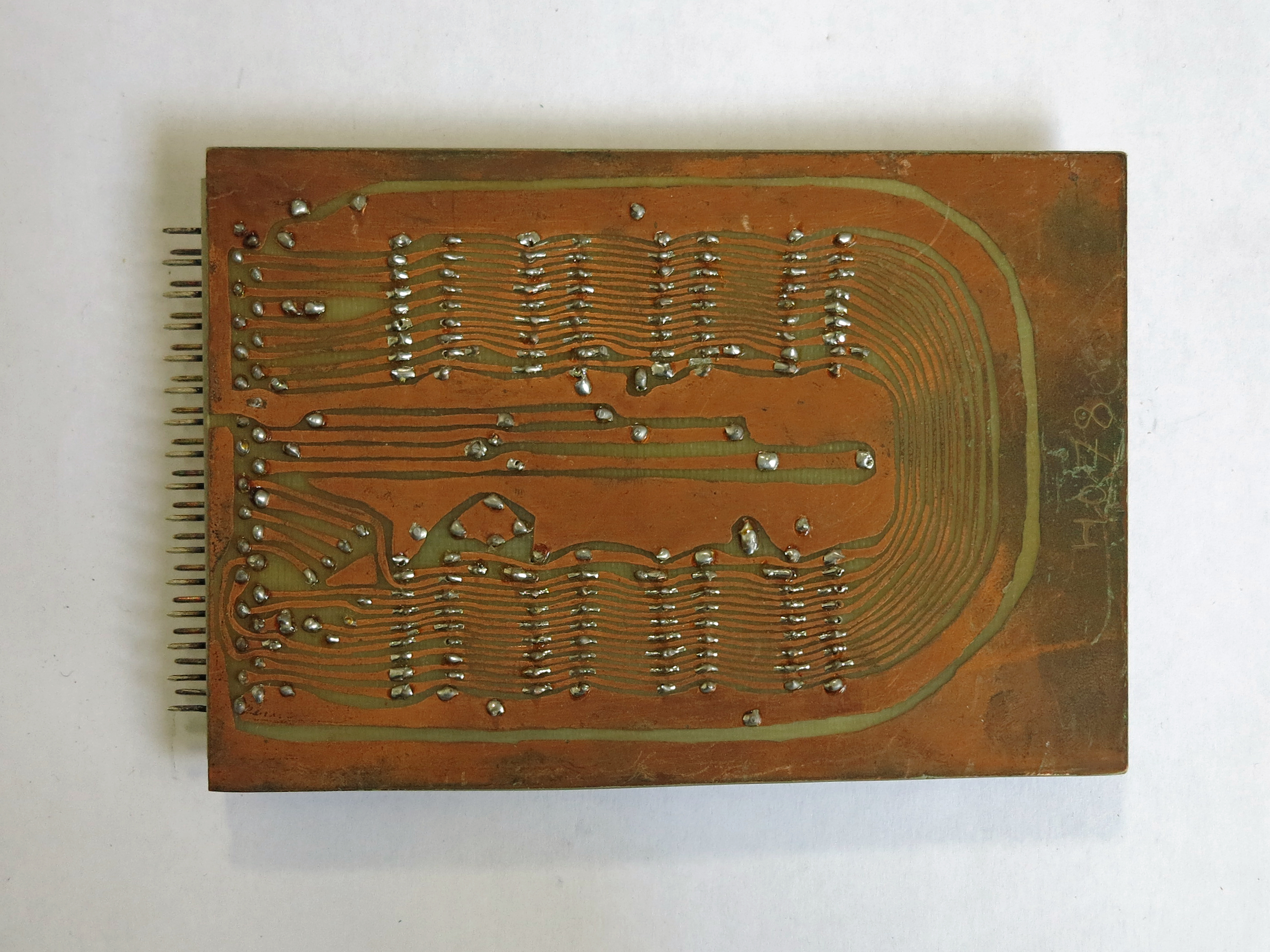
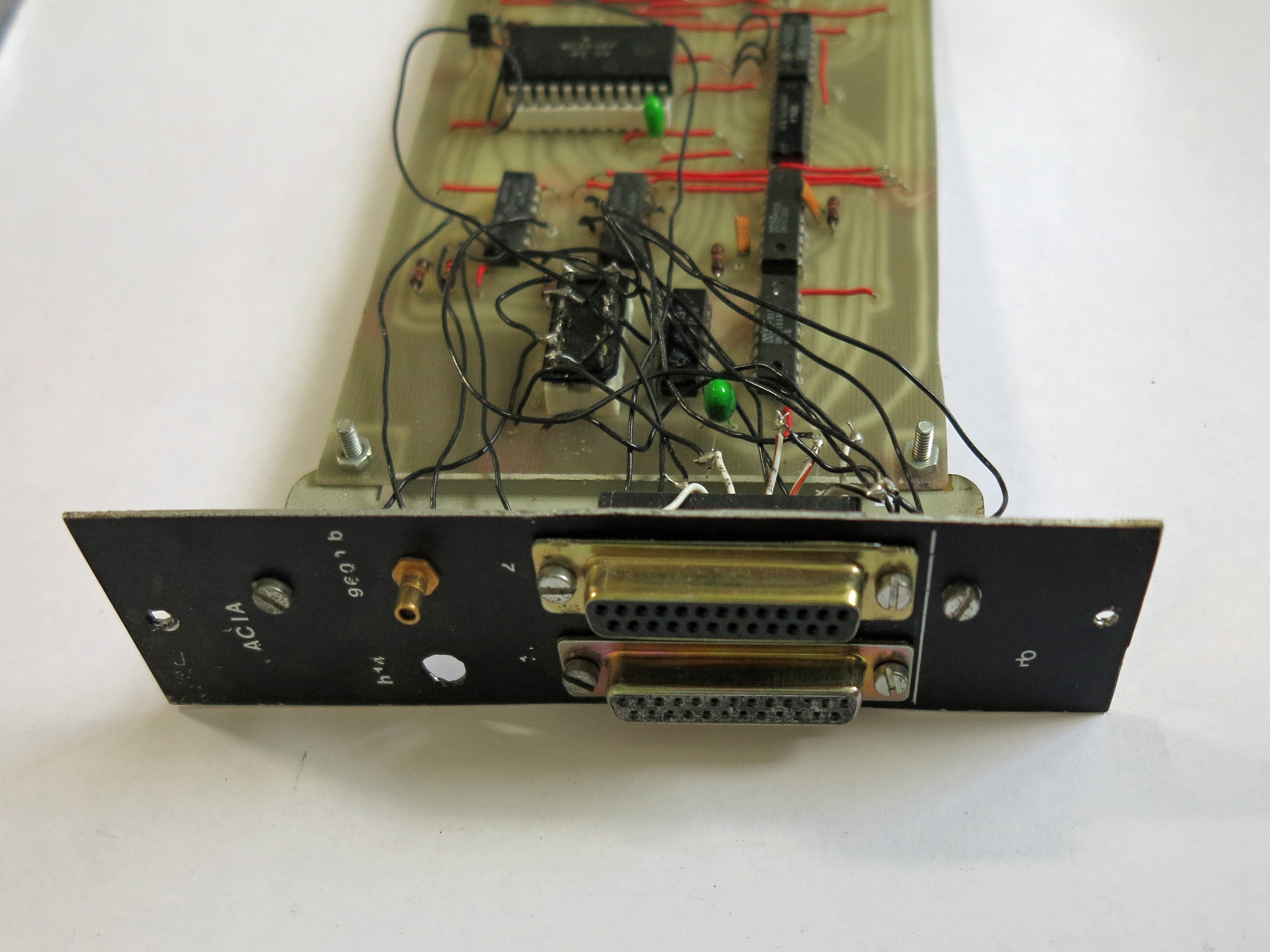
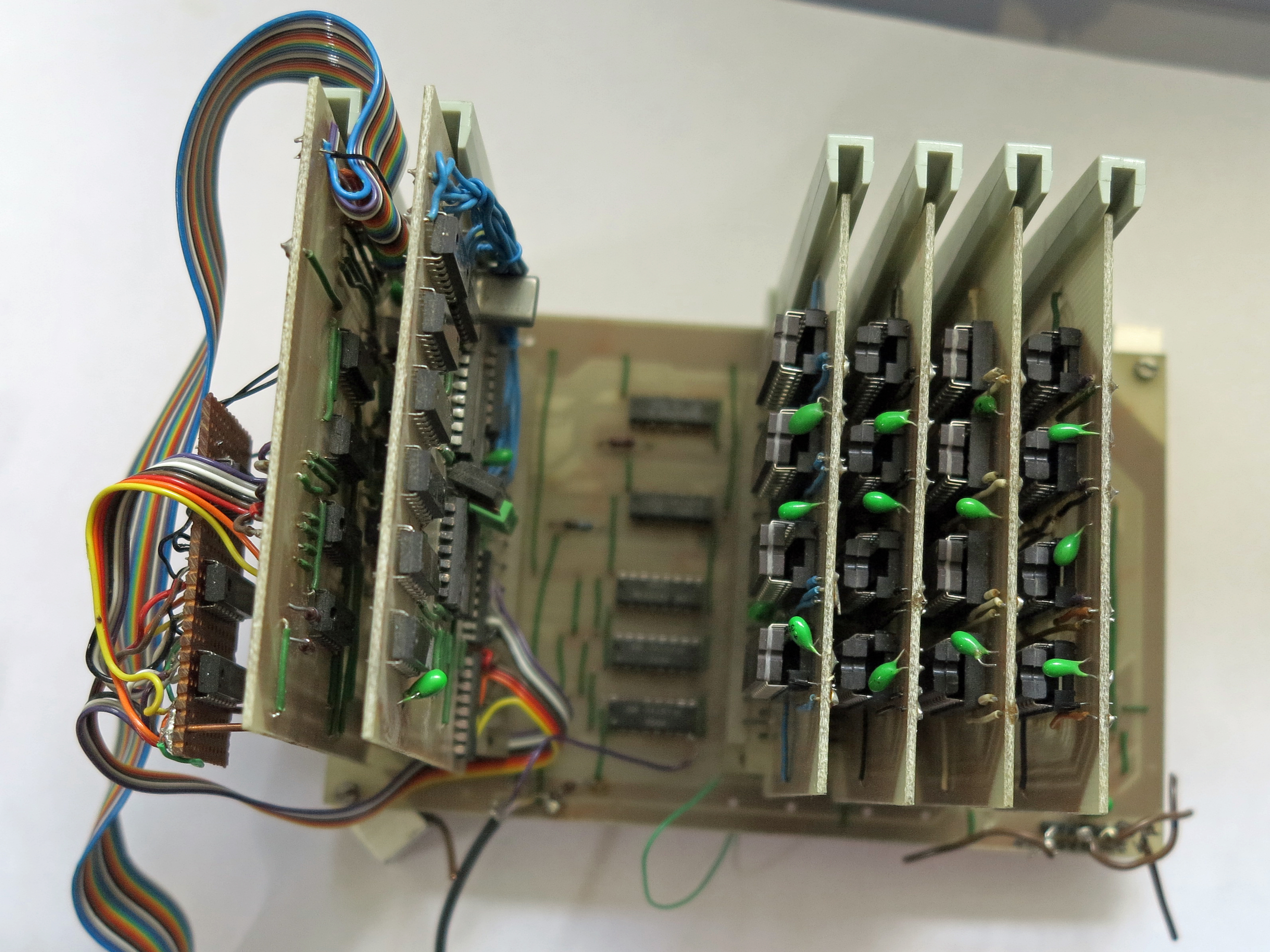
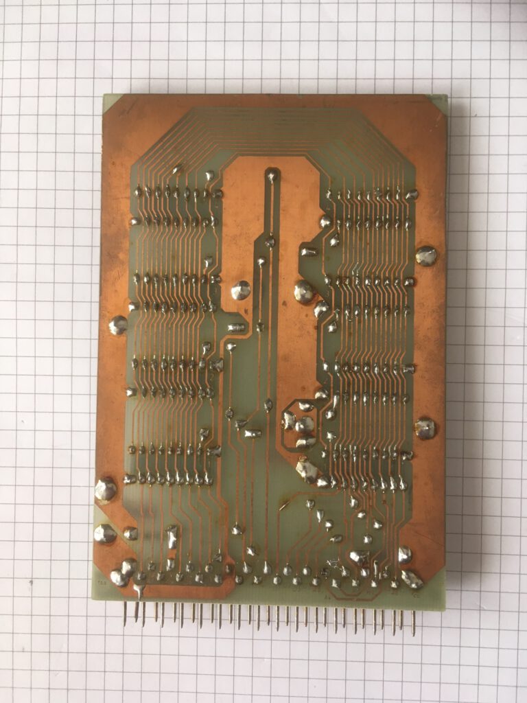
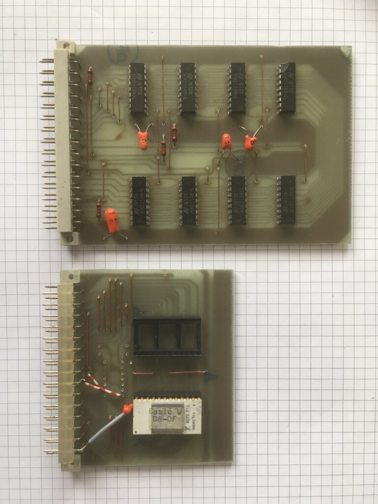
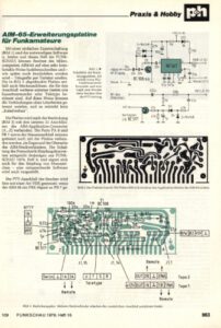
 4K SRAM card, Radio Bulletin September 1979