Philips EE20 in South Africa
I received the following story, written by John Lusty from South Africa, with the photographs he made in October 2005. What follows is his story!
The EE20 in South Africa
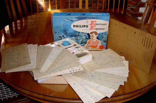
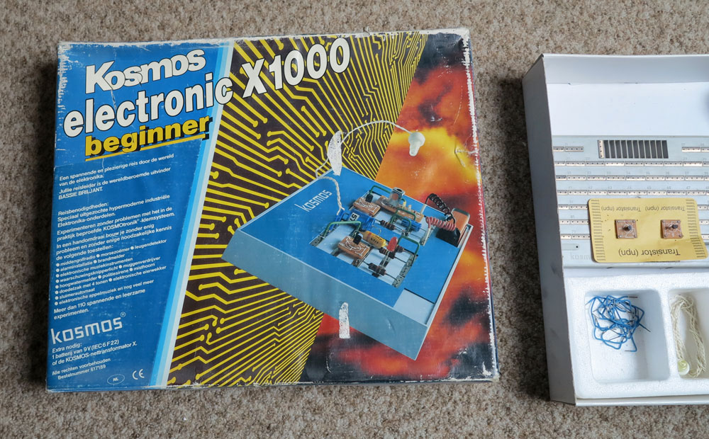
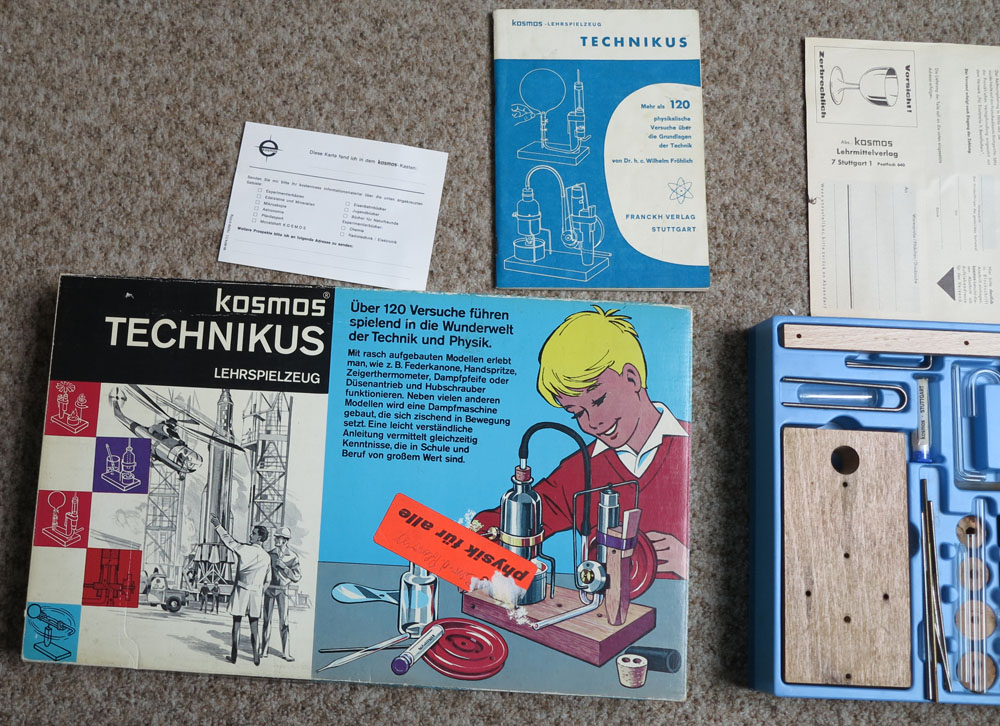
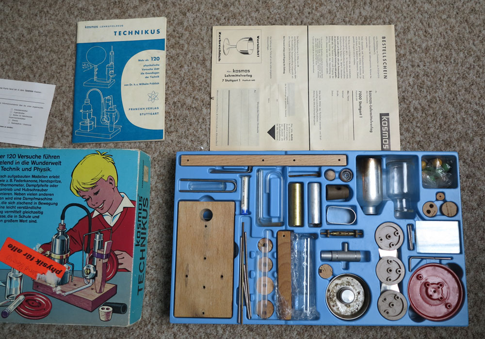
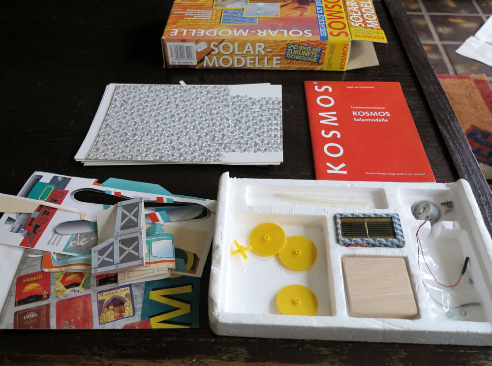
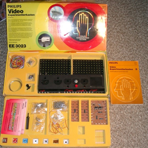
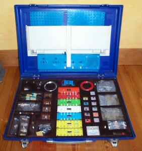
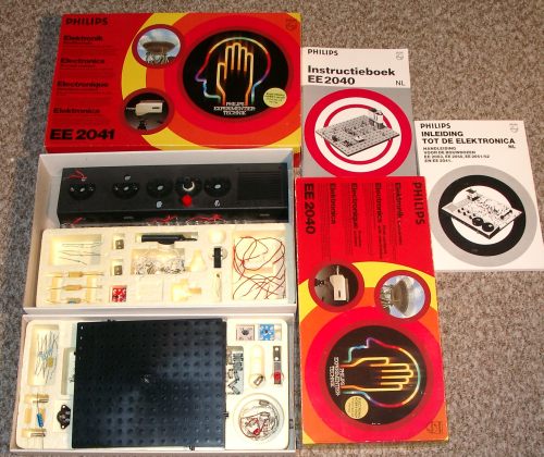
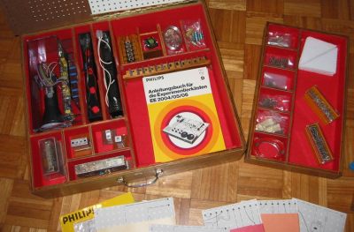
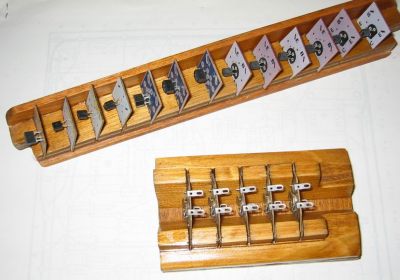
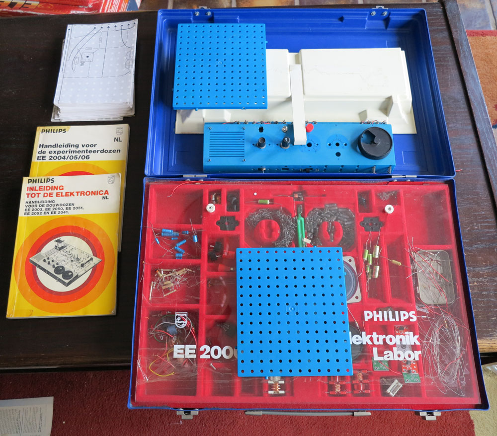
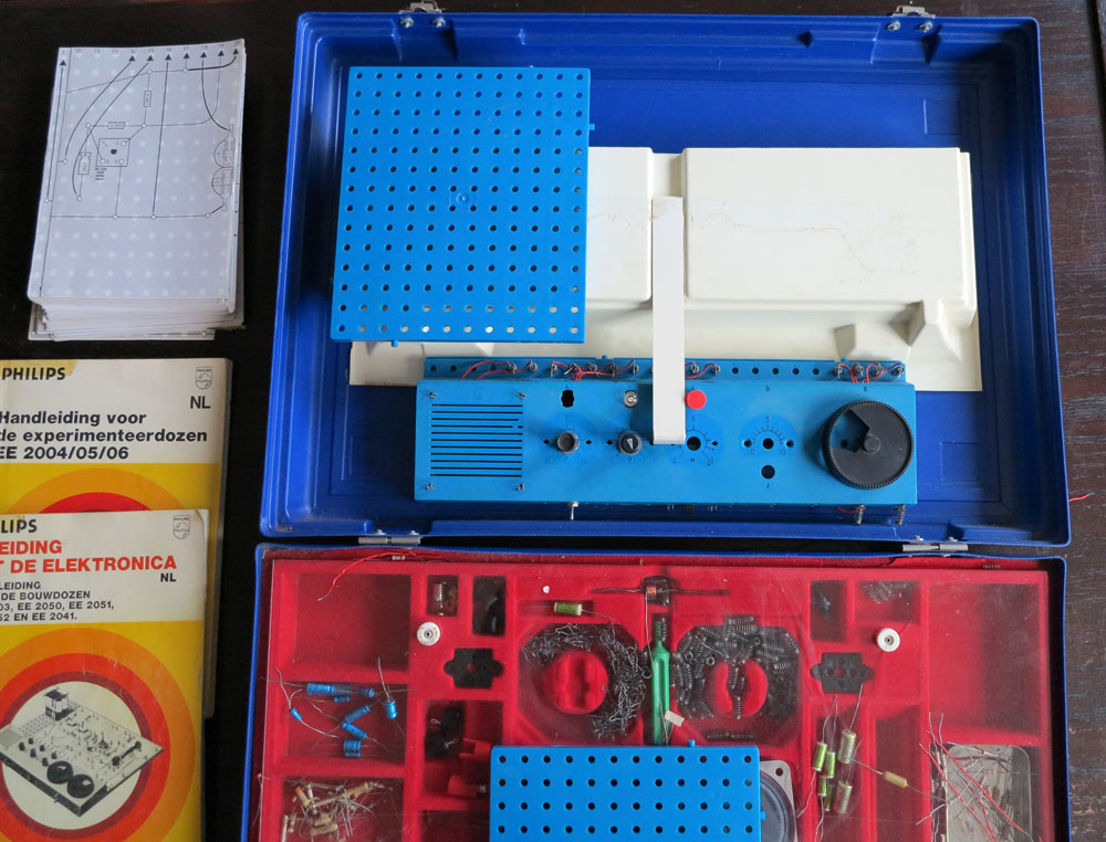
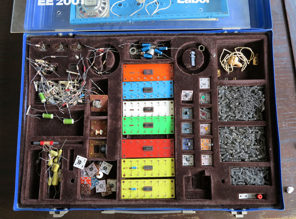
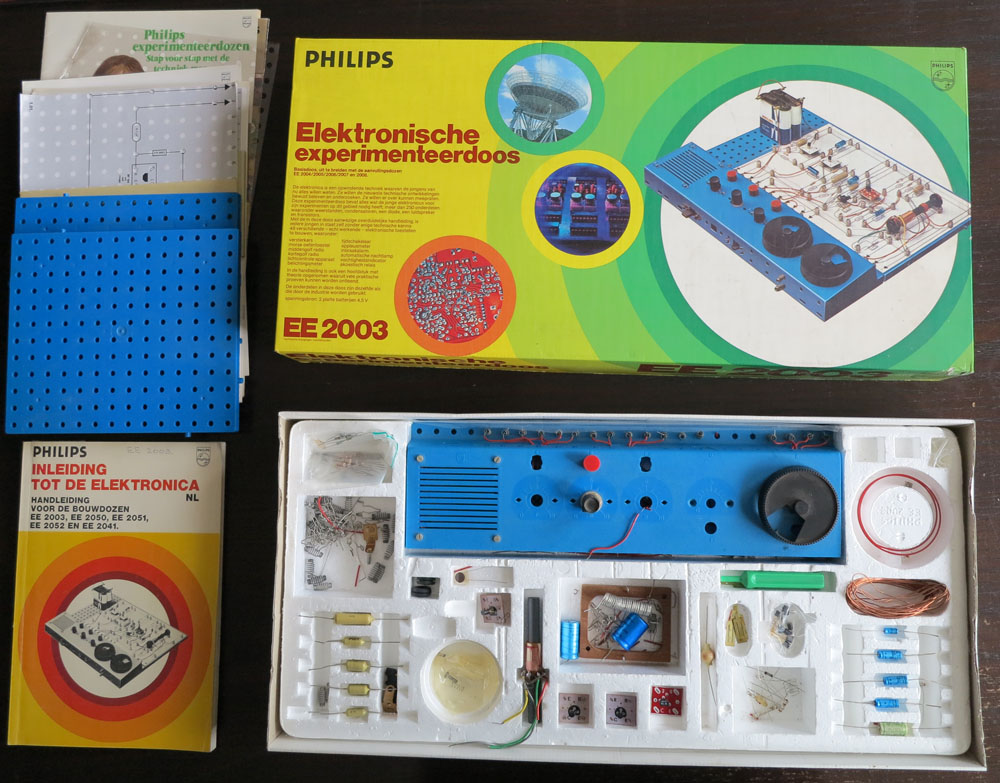
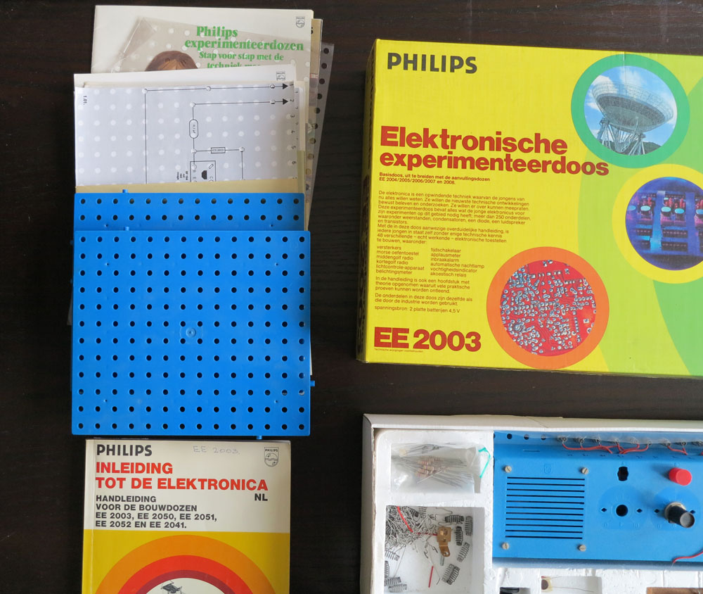
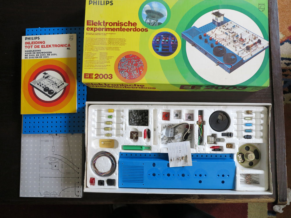
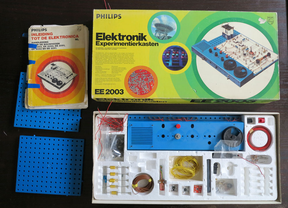
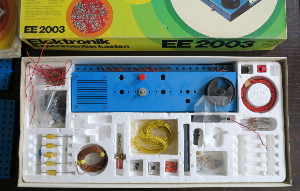
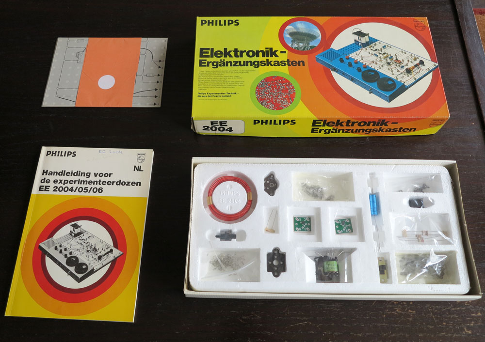
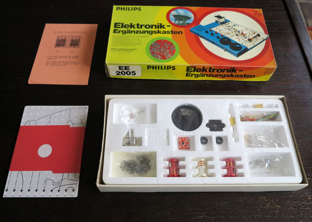
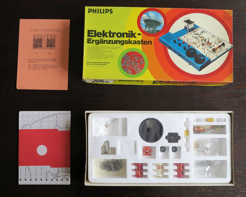
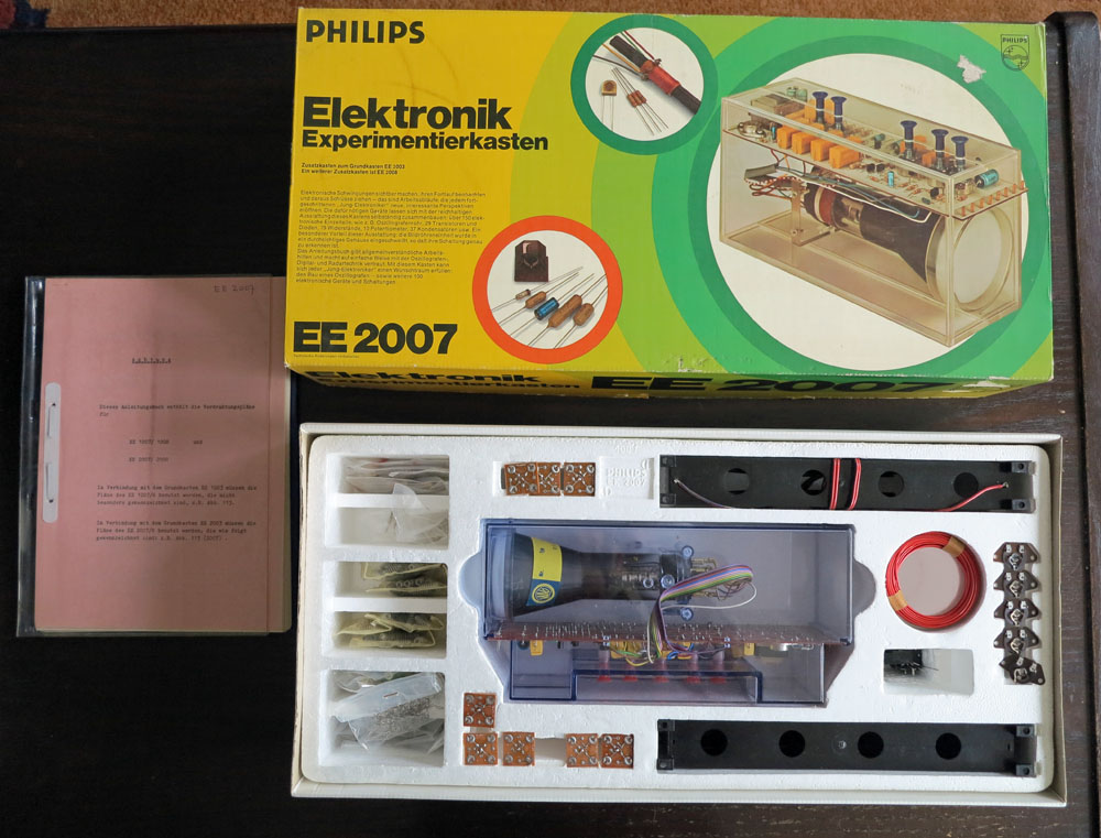
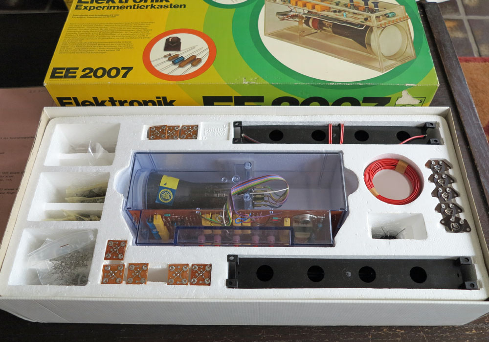
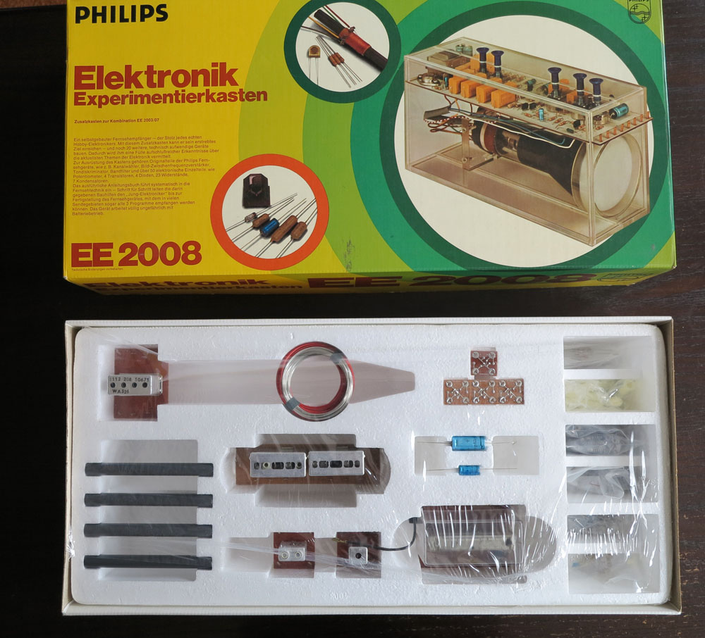
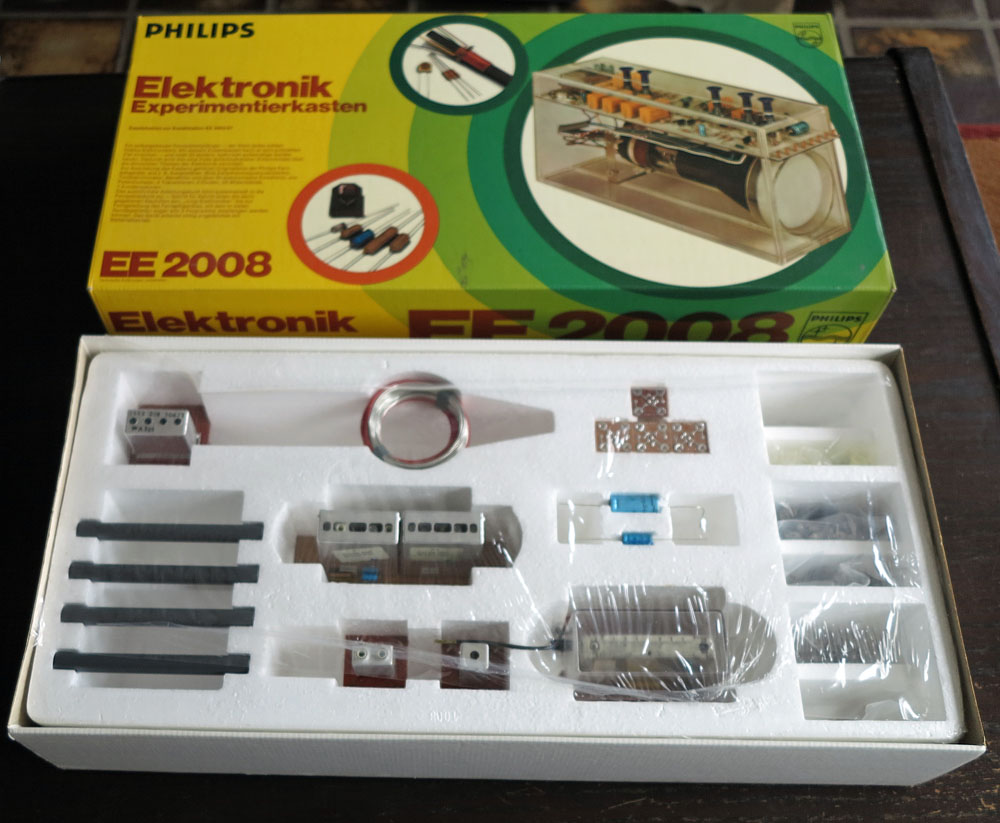
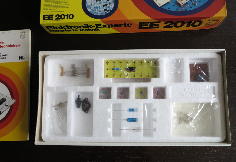
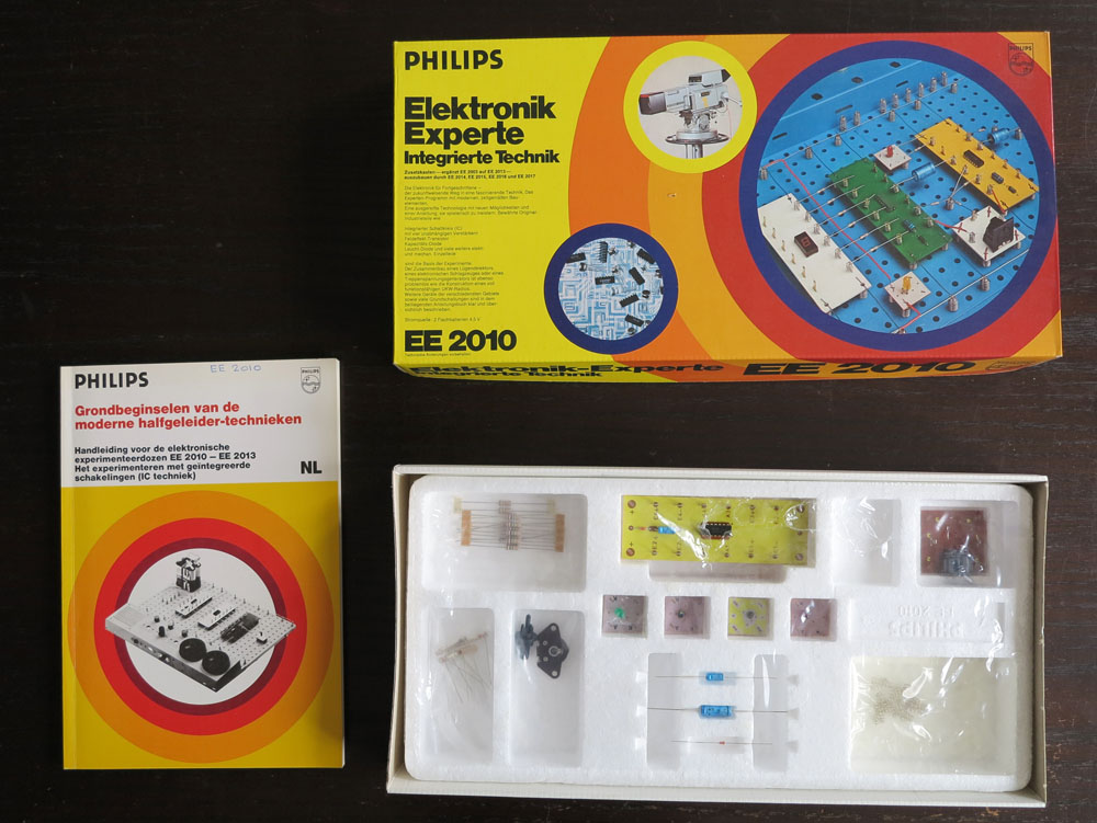
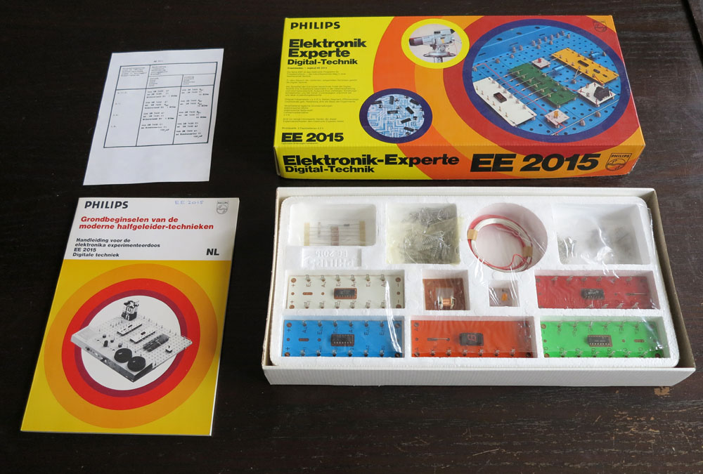
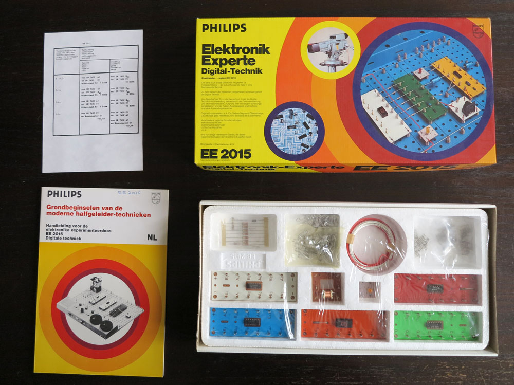
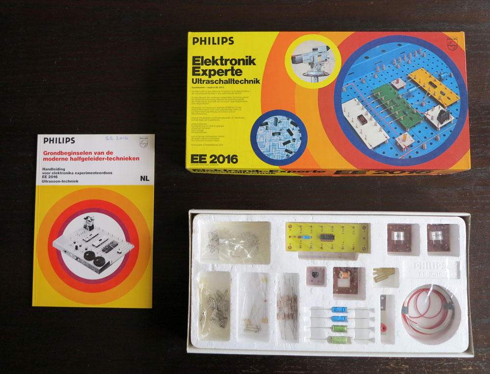
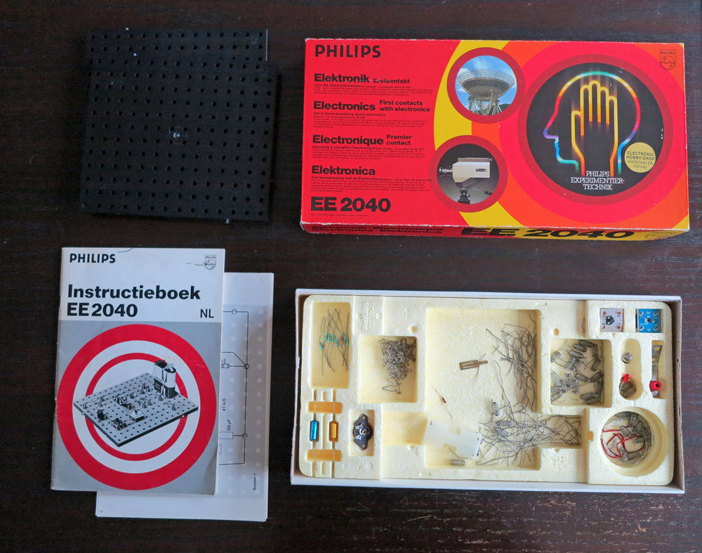
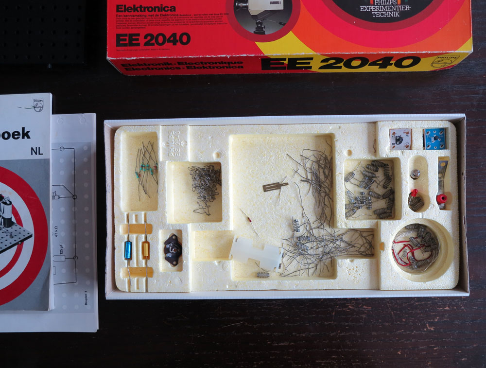
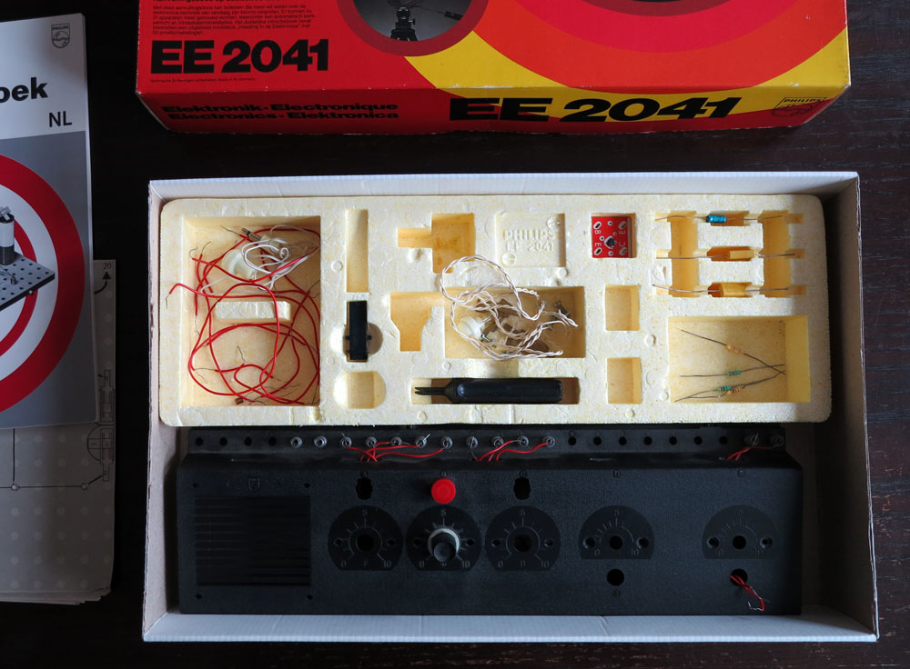
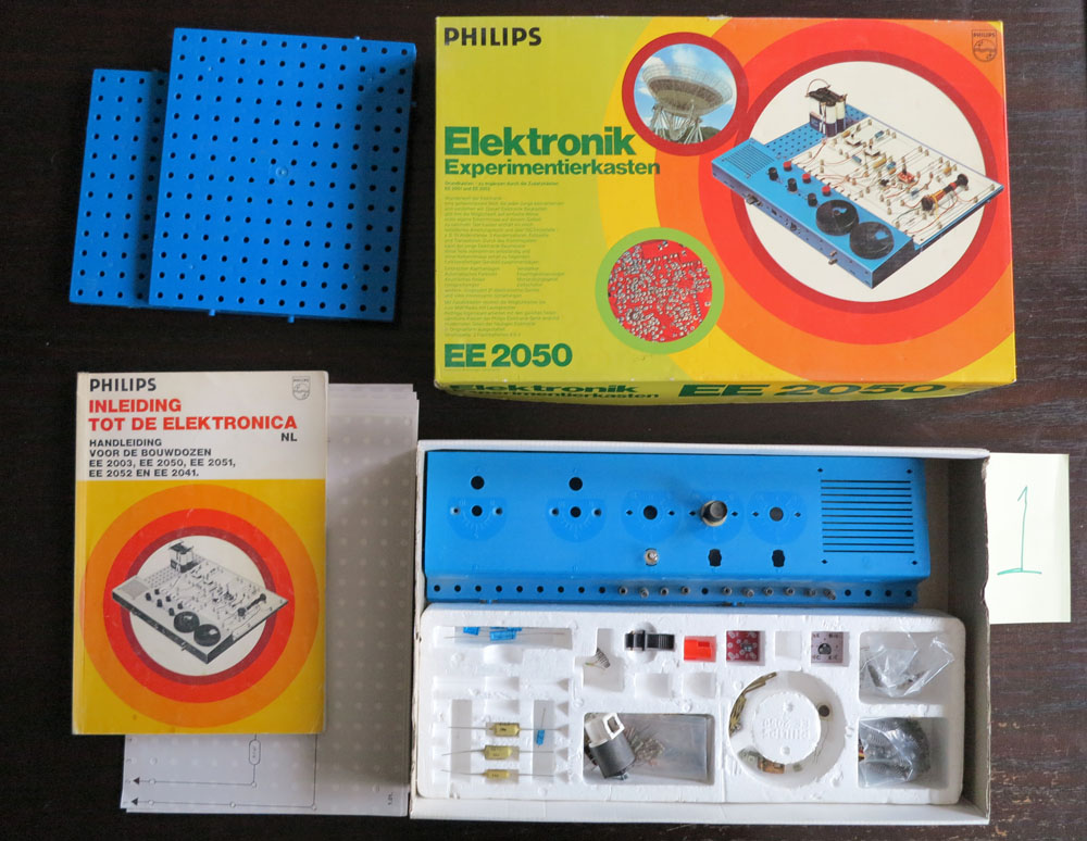
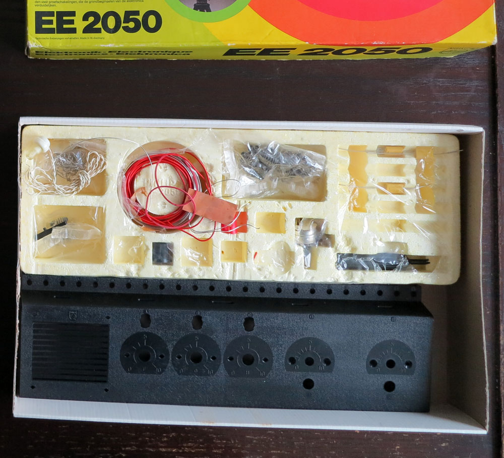
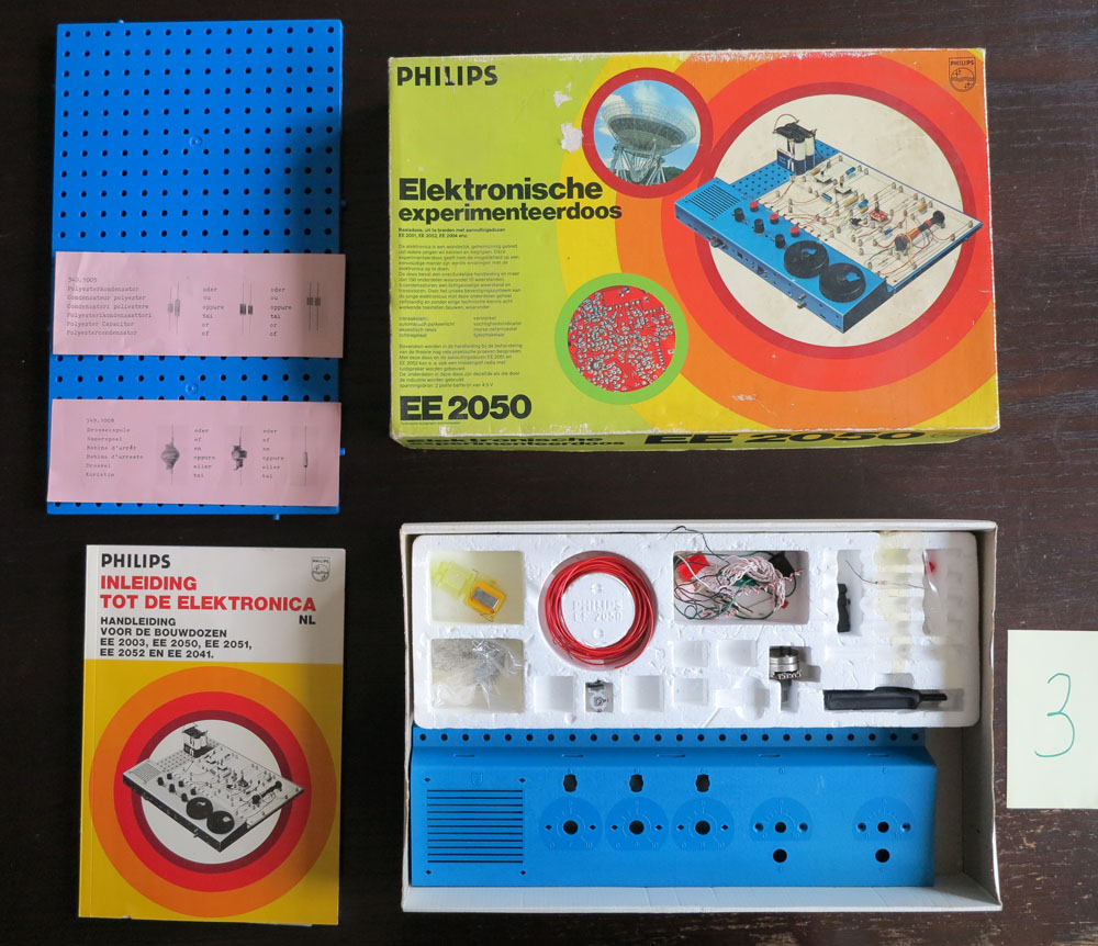
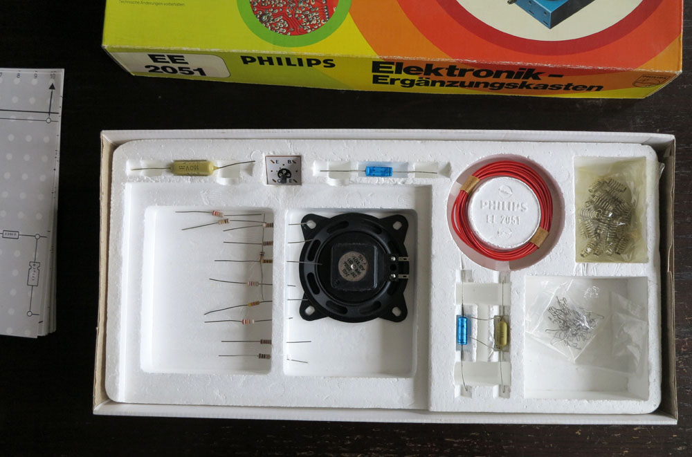
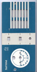
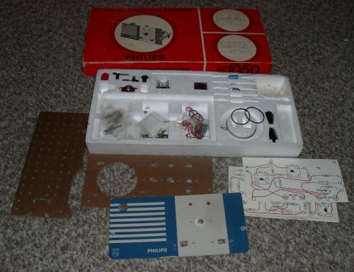
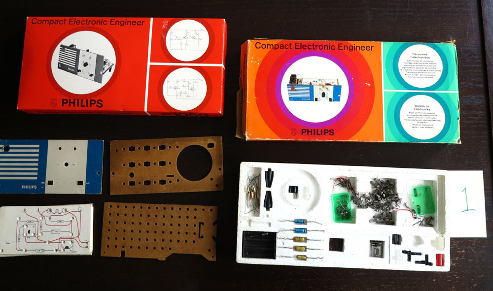
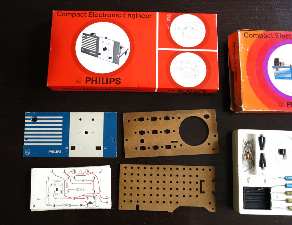
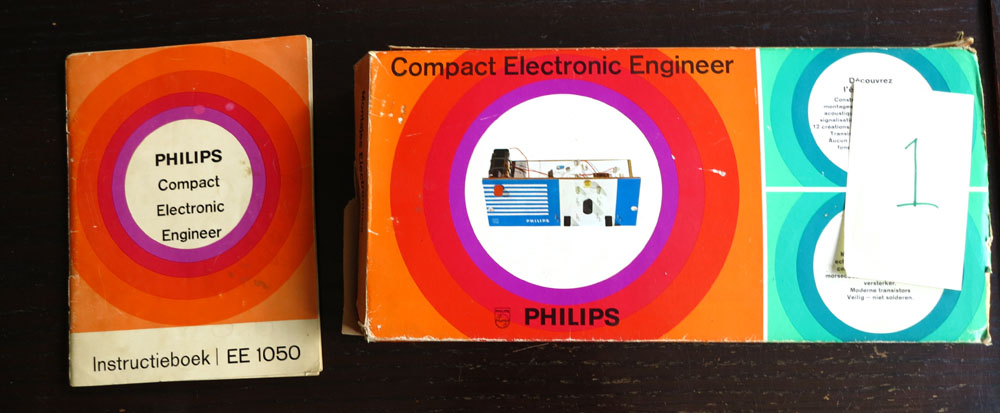
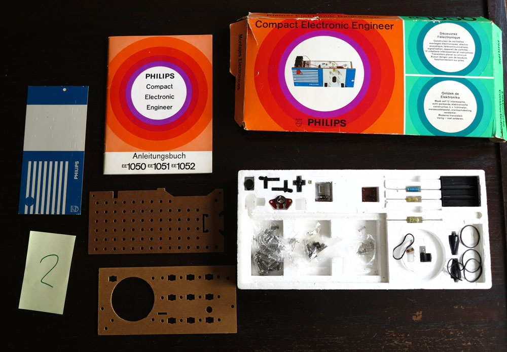
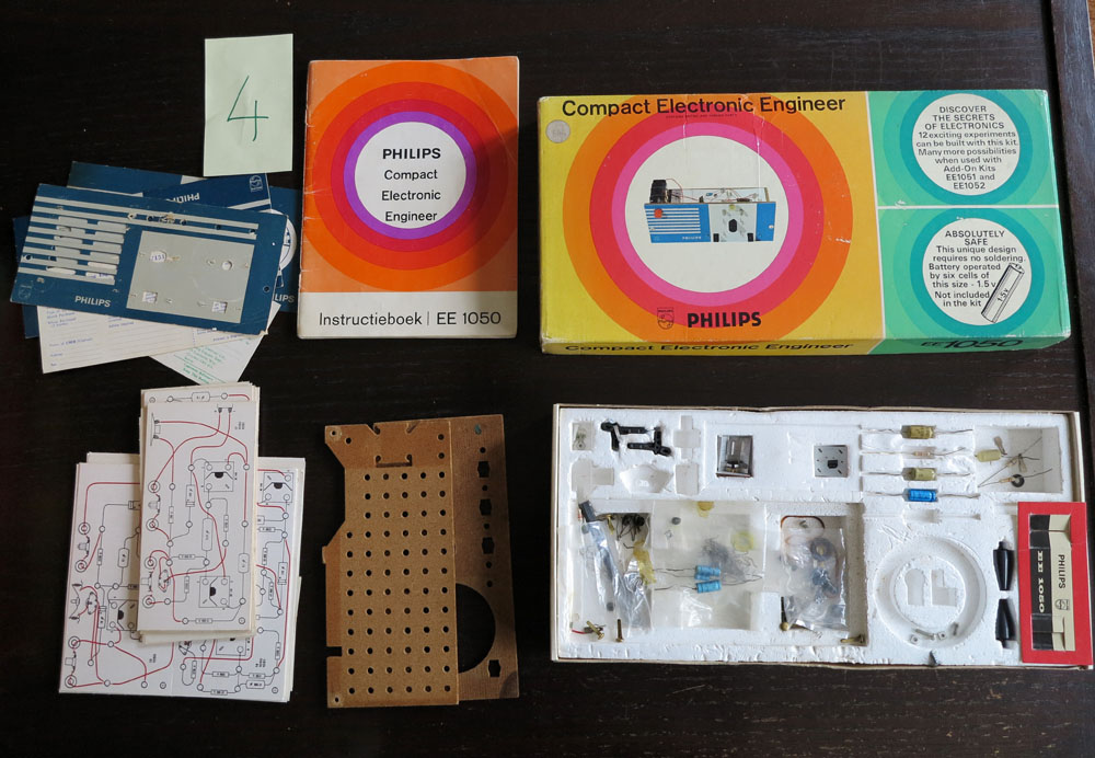
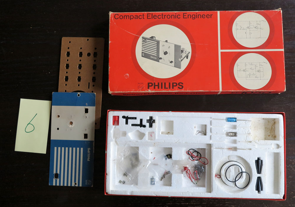
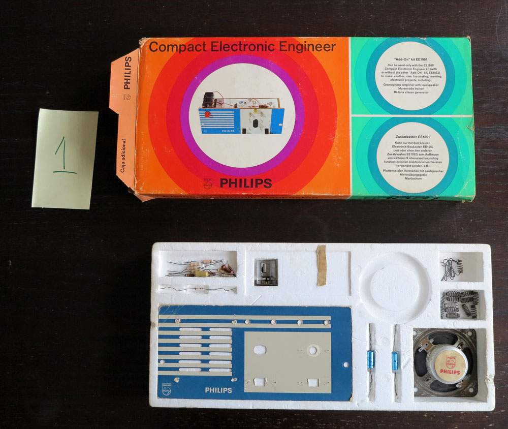
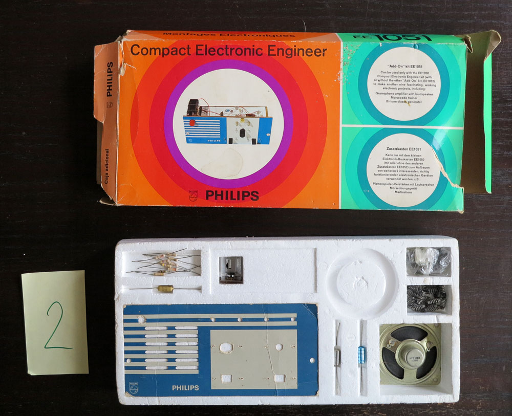
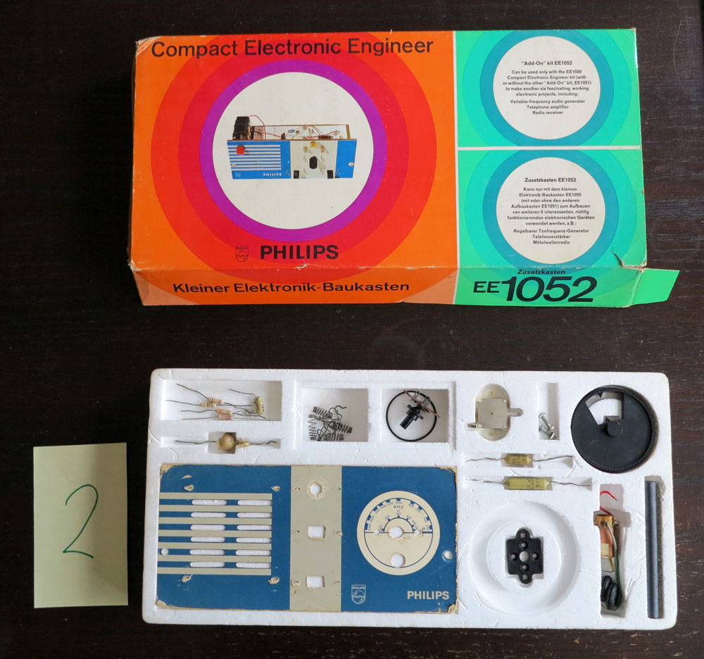
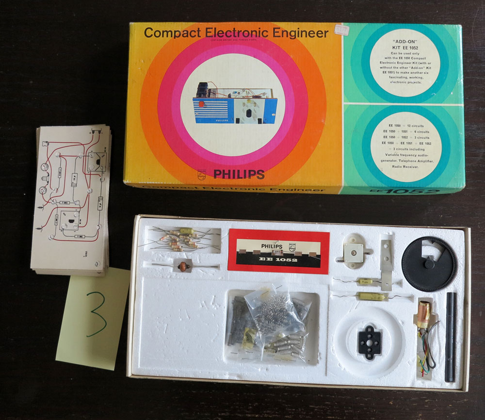
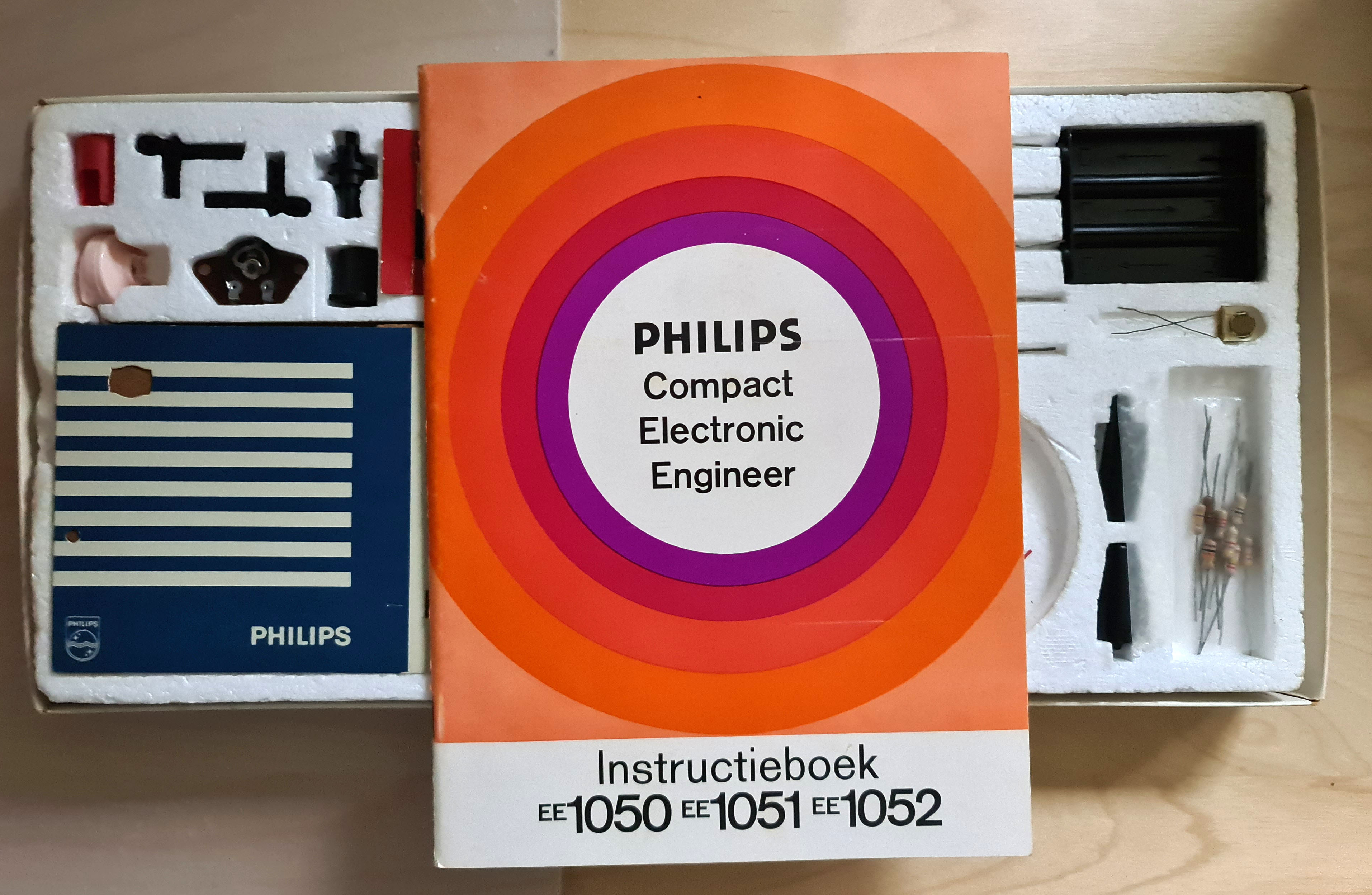
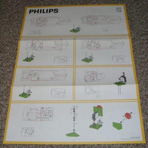
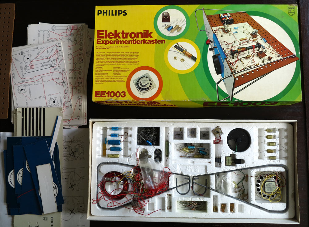
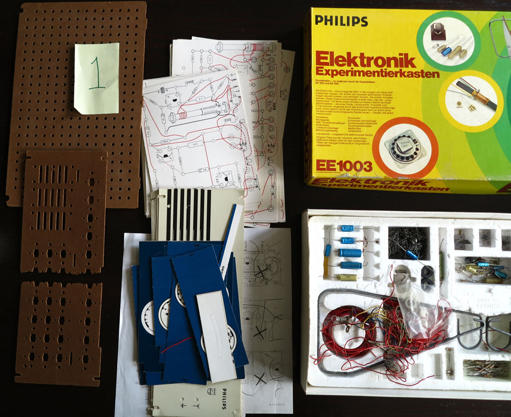
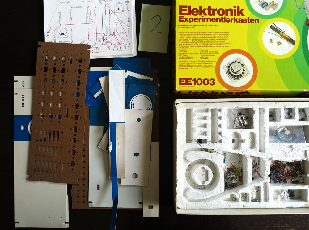
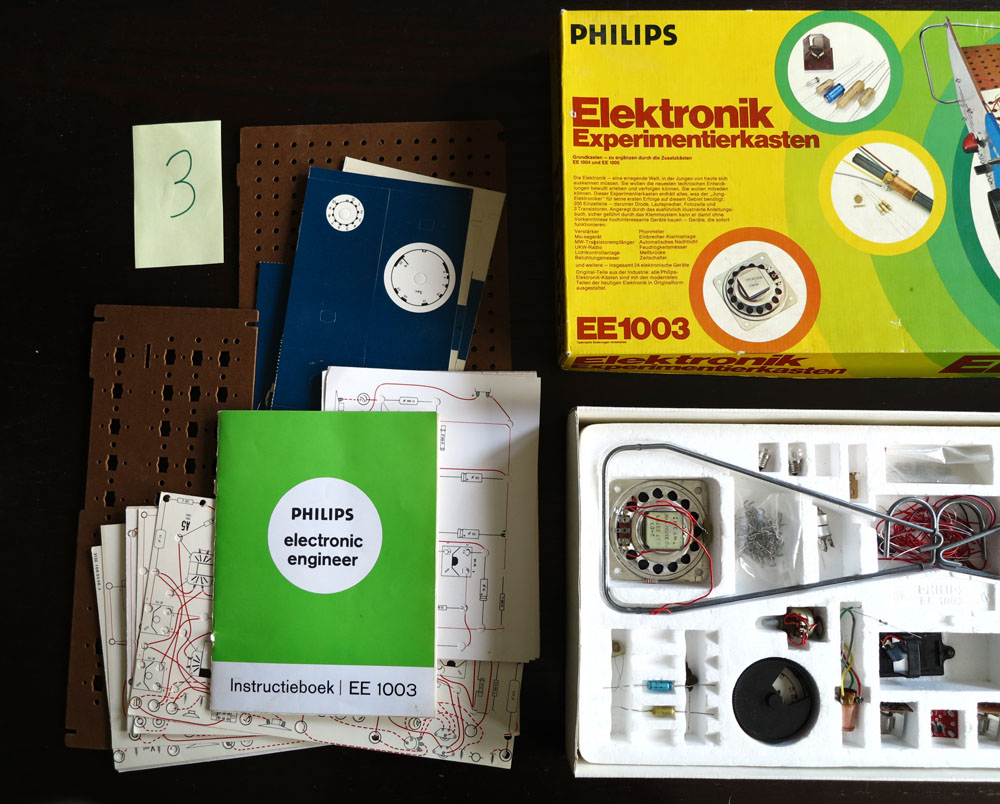
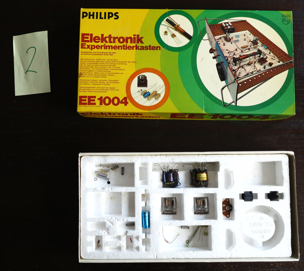
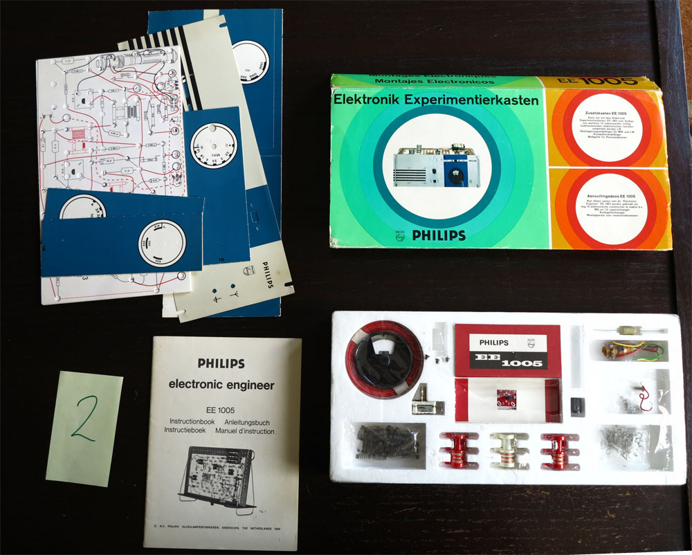
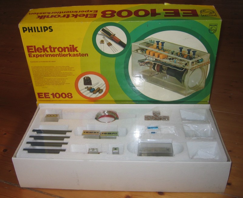
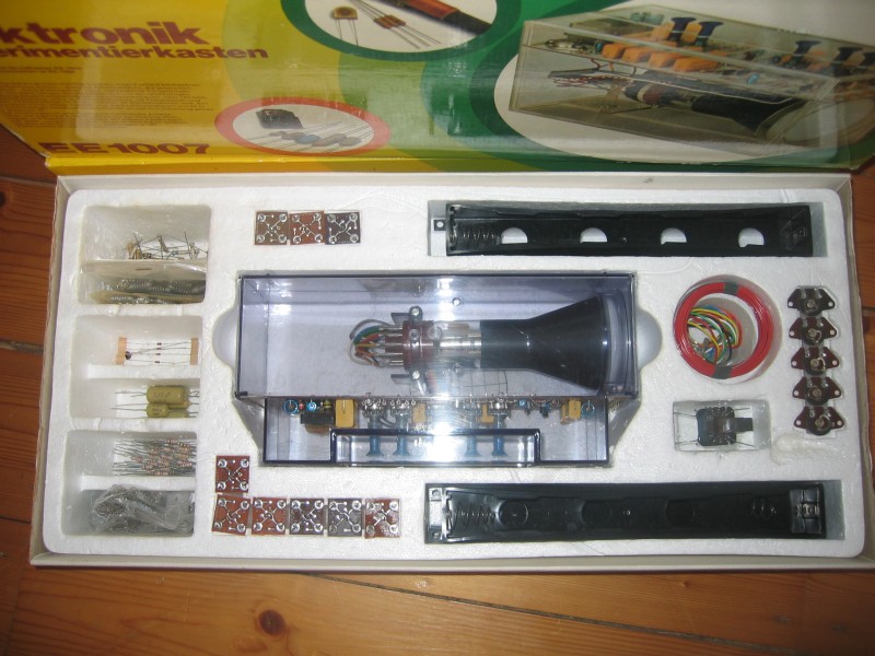
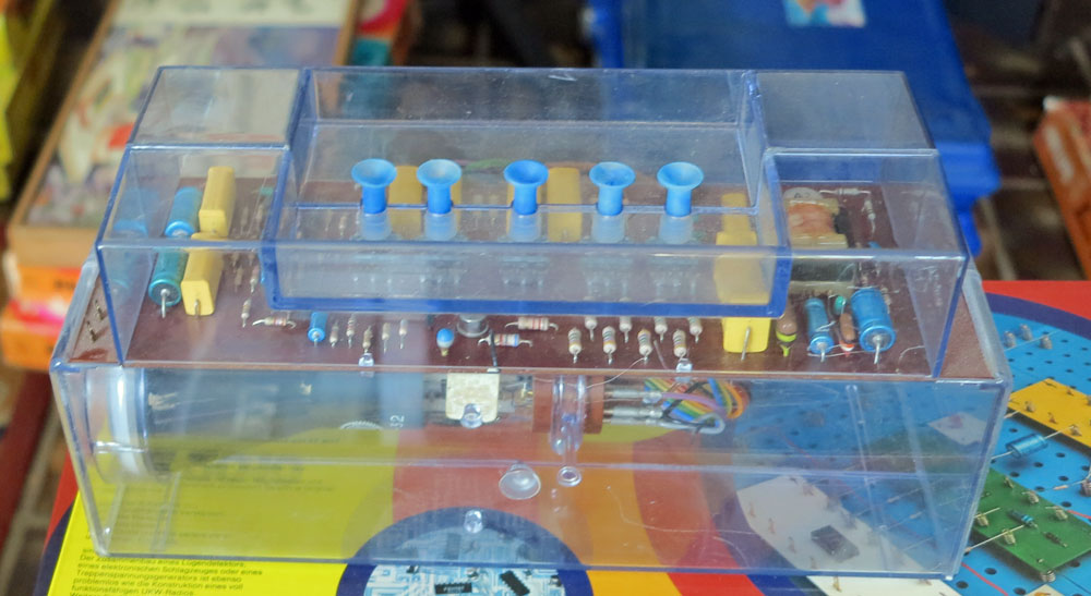
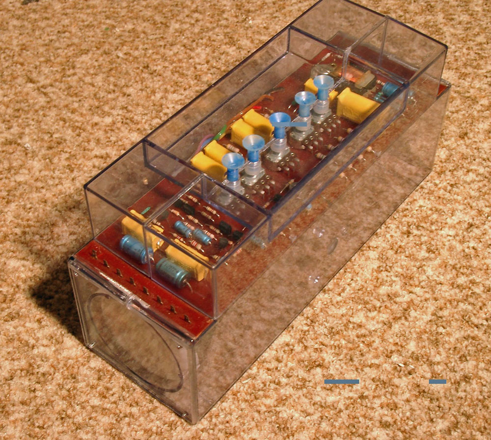
A general view of my EE20 kit, showing that it is still complete, including ALL the templates!
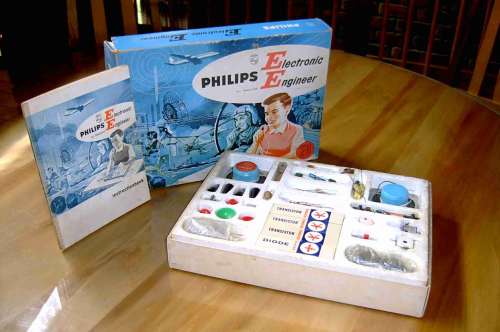
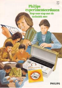
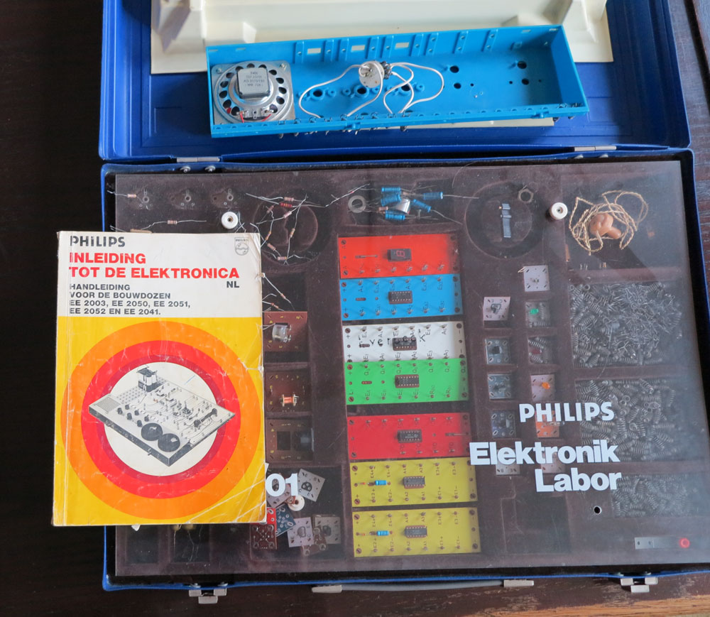
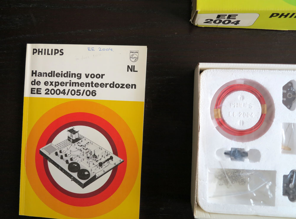
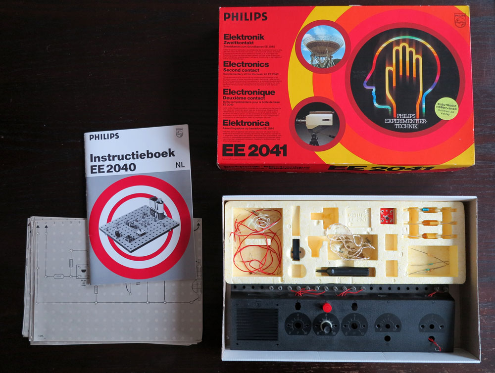
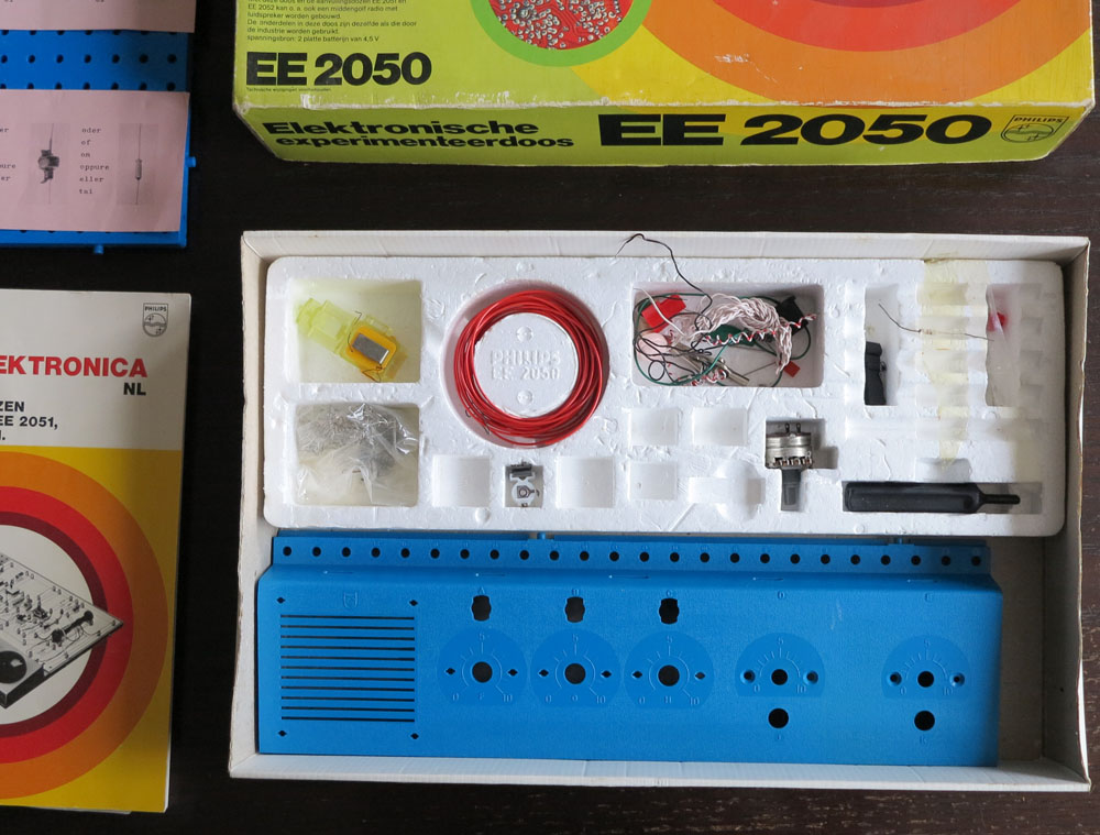
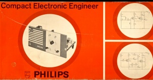
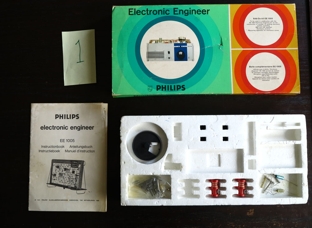
Another view which includes the Instructionbook, still in good condition !
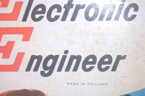
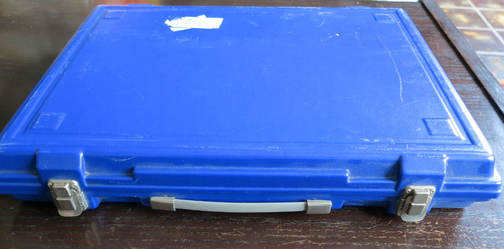
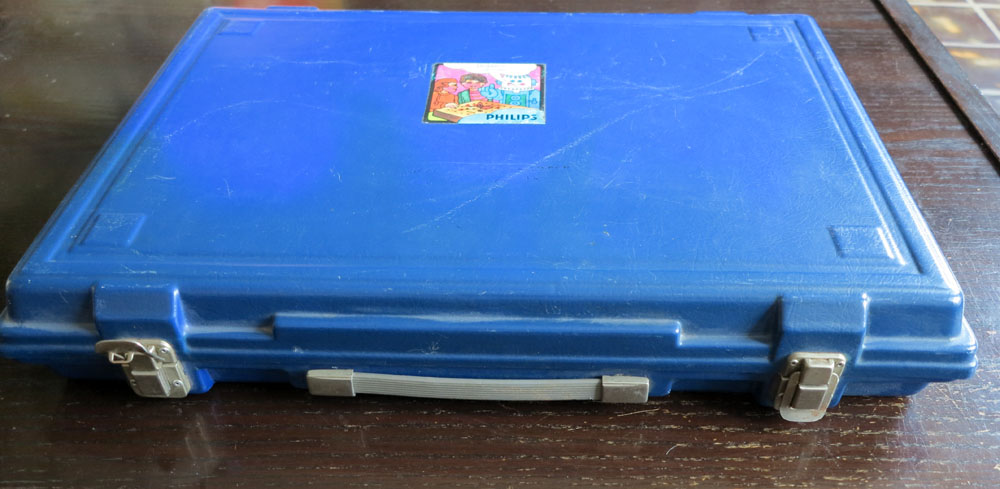
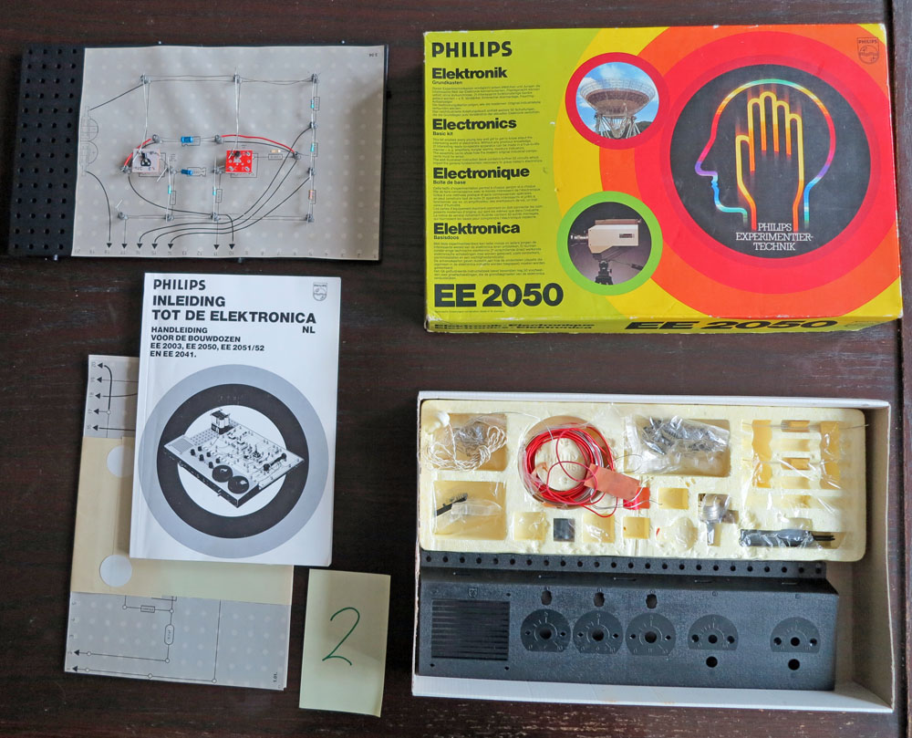
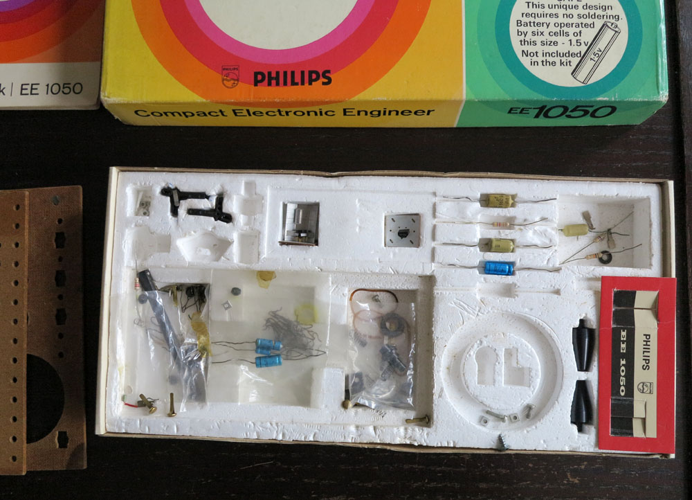
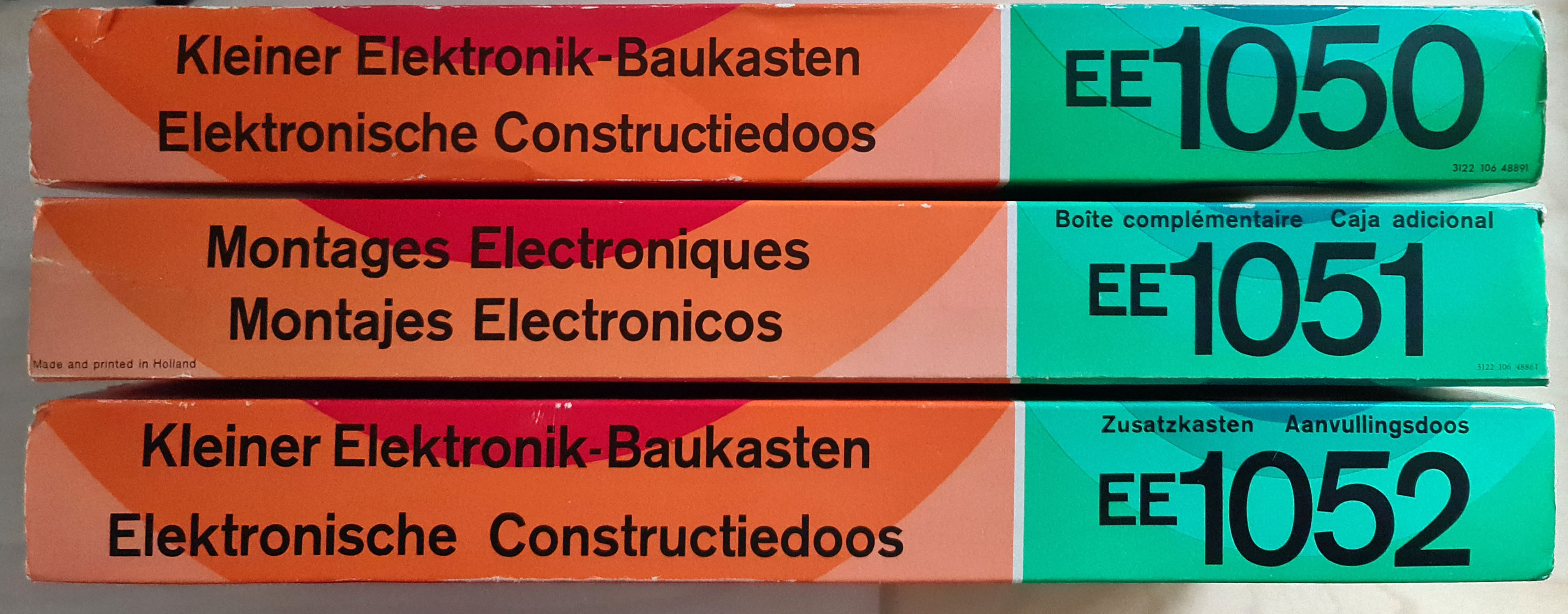
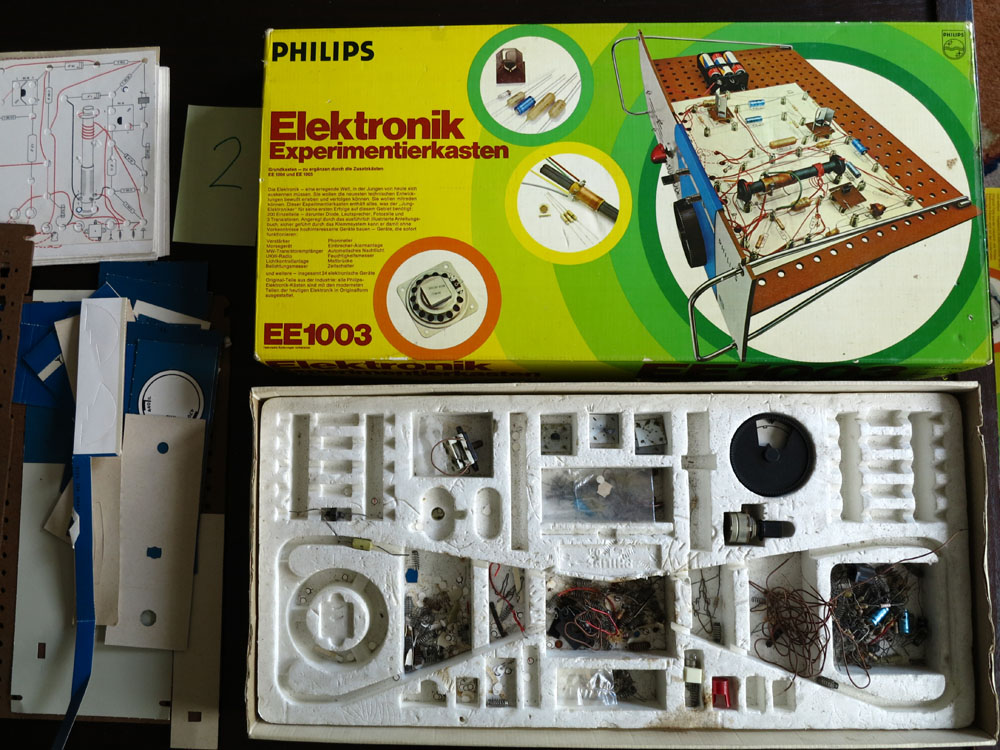
A close-up of "Made In Holland" on the box. It seems like I have an original kit, imported from Holland. This is not surprising, as our ties to Europe have always been strong, and Philips is still a major corporation in South Africa today.
My story of how I came to get my EE20 kit is in some ways typical, but has one rather interesting twist in it :
From the age of about 9 or 10 I become interested in anything electrical; I liked to play with batteries, little electric motors, torch bulbs, switches etc, and from there, I progressed to radios and amplifiers, and wanted to understand how they worked. My father was a musician, but had been an Officer in the Royal Core of Signals in the British Army during World War II, and so he had some basic electronic knowledge (but only for valves, not transistors !). I also listened to the radio a lot, and when I was 11 years old in 1965, I heard a radio commercial for the EE20 kit, on our local radio station Springbok Radio. The programme was called "The World Of Philips", and as soon as I heard about the kit, I knew I wanted one. A few weeks later, I saw the kits in a local store, and knew from that moment onwards that this is what I wanted ! I became totally obsessed with the idea, but had to wait a few more months until Christmas, before I could get it. The price for the EE20 at that time was ZAR20.50 in local South African currency, which is about Euro2.50 !!!
And now for the very unusual part of the story. You may recall that in 1967, South Africa’s Professor Christian Barnard performed the world’s first heart transplant. The young woman who was the donor had been killed in a road accident, together with her Mother, and it was this lady ie the donor’s Mother, who had sold me the Philips kit in the store. I recognised her photograph in the newspaper, two years after getting the kit. I found this a very strange coincidence indeed. You may find some of my experiences with the EE20 interesting.
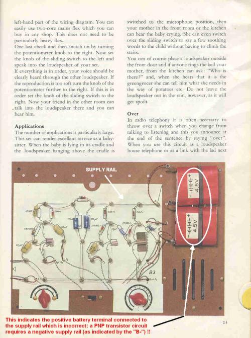
On Christmas day, 1965, I received the EE20, and could not wait to build my first circuit. I remember it was the Morse-code trainer, circuit B1 of the kit. However, the battery polarity was not clear; the template has a "B-" to indicate negative, but ALL the photographs in the Instructionbook indicate that this is connected to the positive terminal of the battery. Knowing that incorrect battery polarity could damage a transistor circuit, this worried me quite a lot. We reasoned that the photographs must have been correct, as we assumed these were working models, and so I connected the battery as shown in the photographs. The photographs were actually incorrect, and so the circuit would not work. I was so upset, until we reversed the battery polarity and everything was fine. Philips later corrected the mistake in the Instructionbook photographs with an updated edition the following year; refer to the article below for a more detailed description of the error in my Instructionbook photographs.
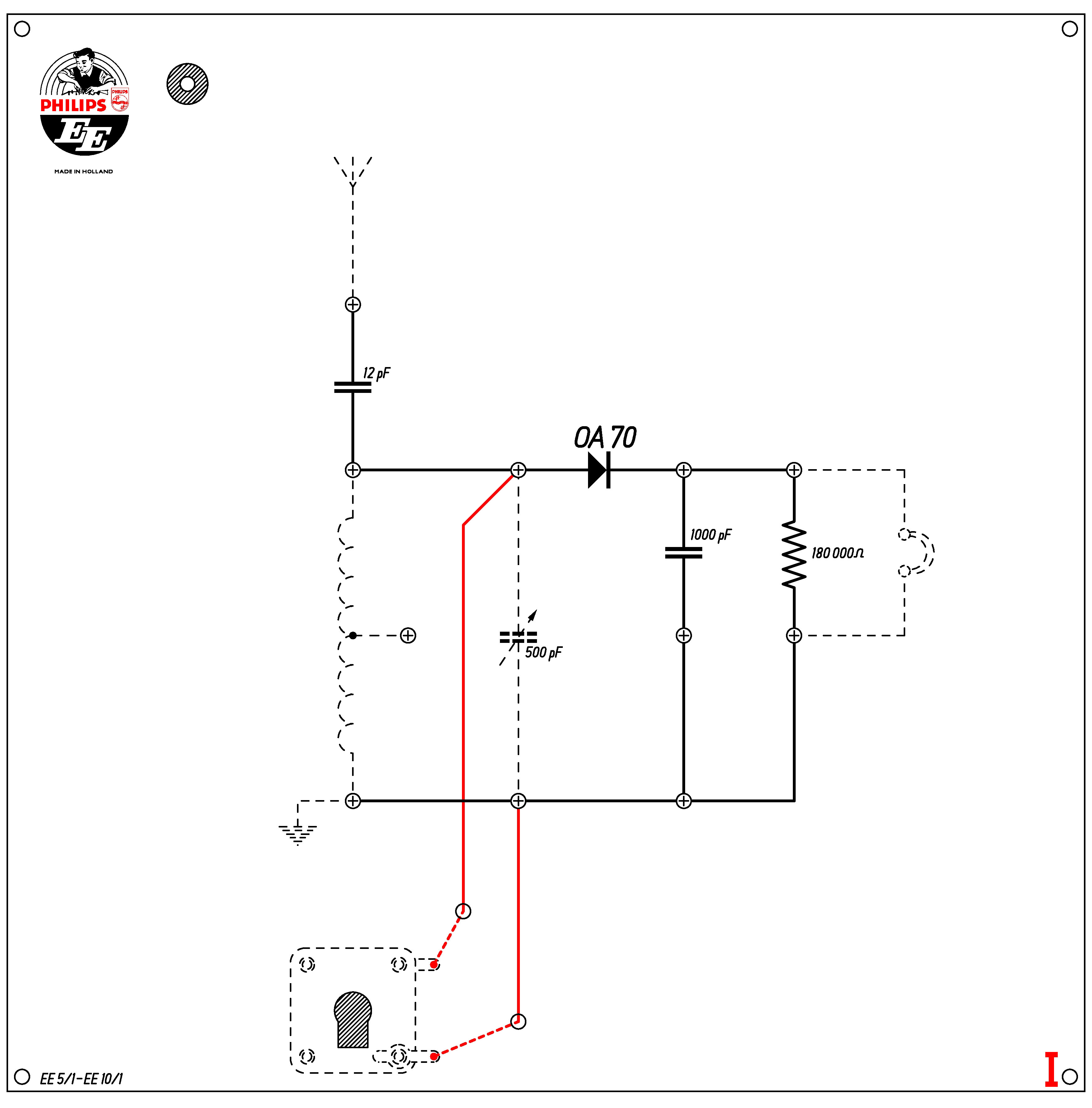
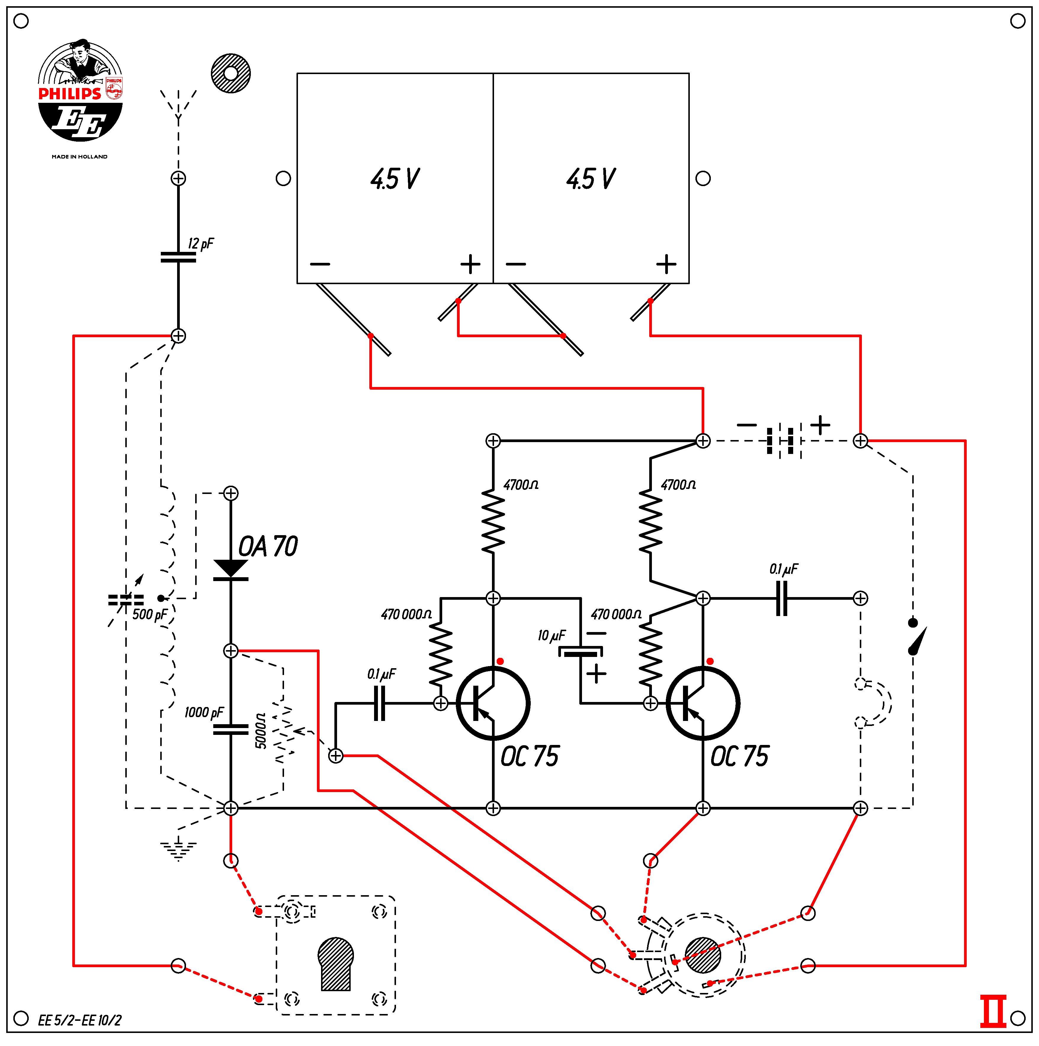
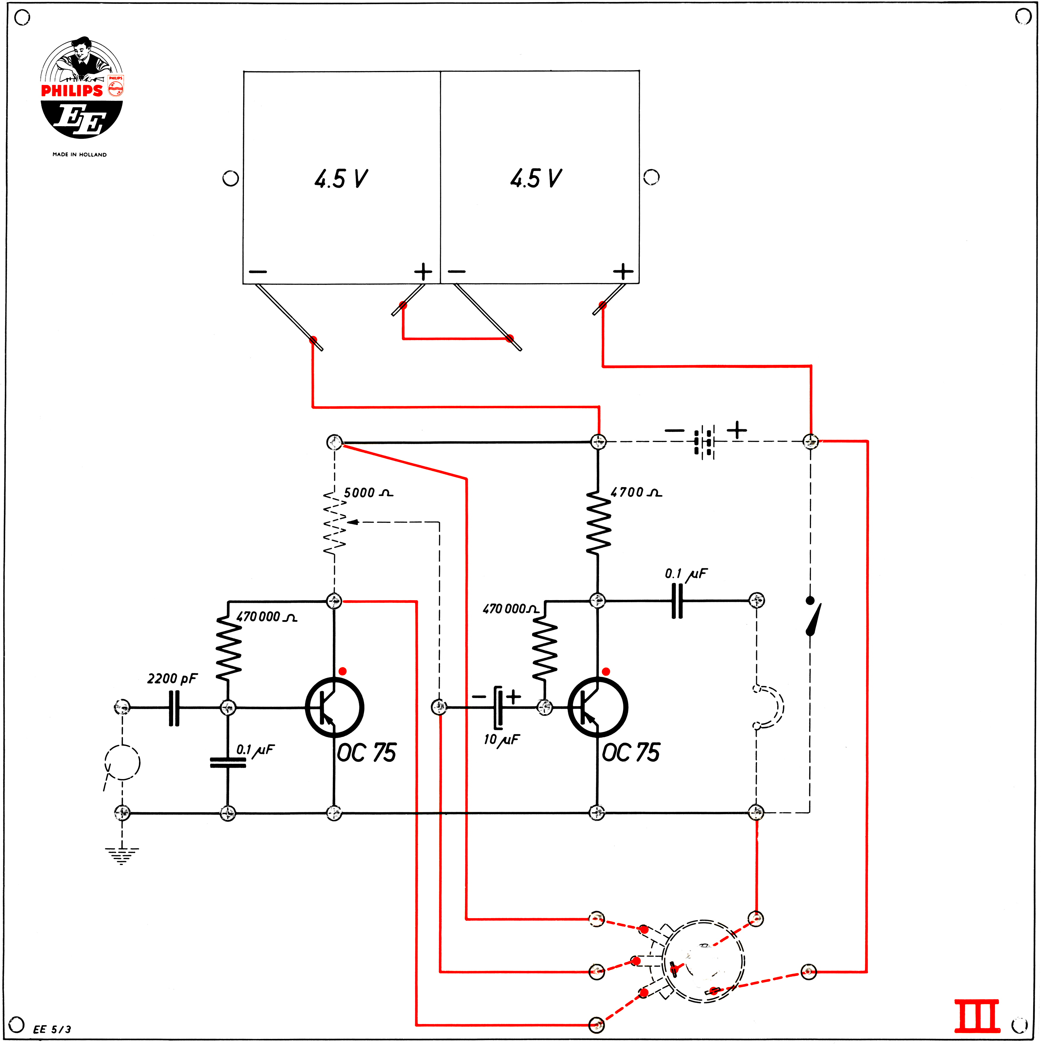
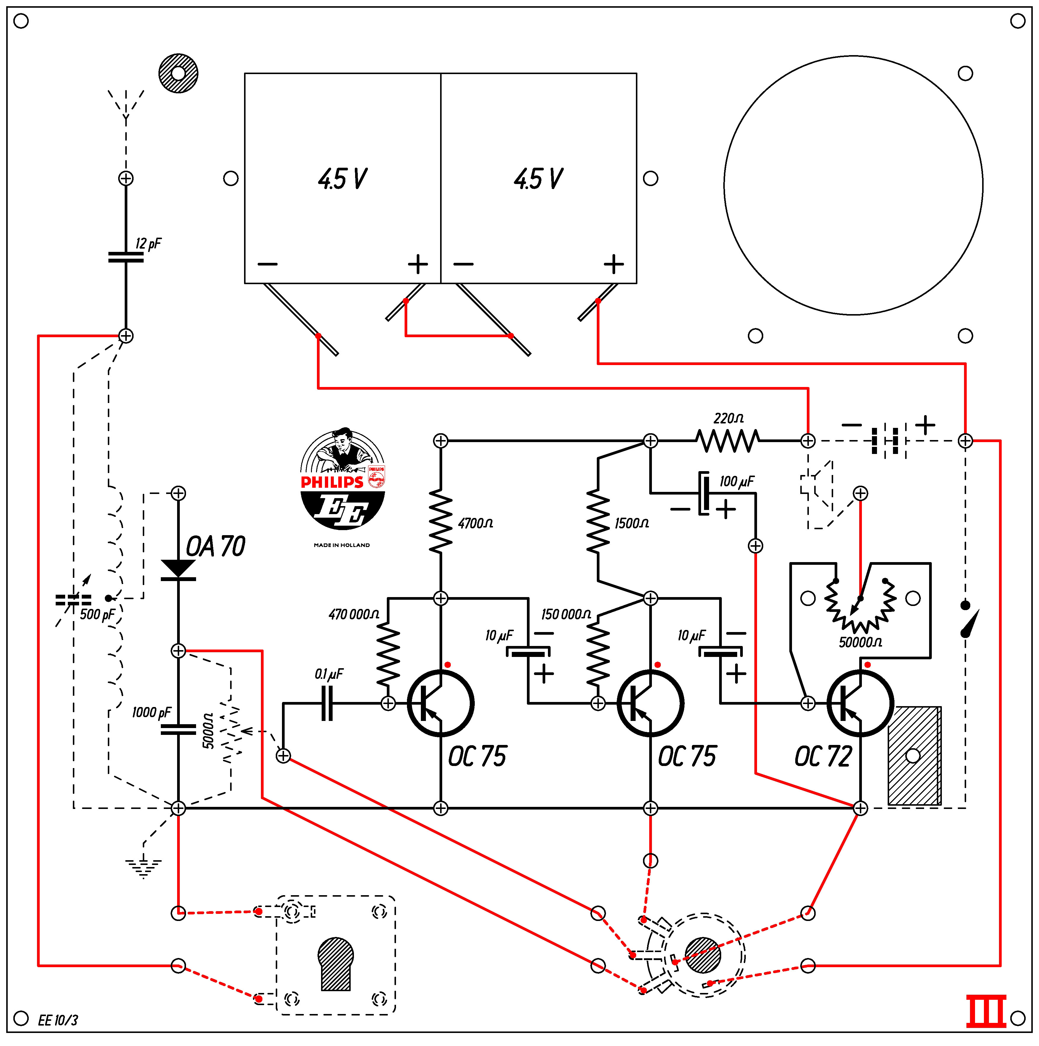
I built most of the circuits, but those which gave me the most fun were the 3-transistor Radio Receiver (Circuit C3), and the Intercom (Circuit B3). I discovered that if you touch one side of the OA79 Diode in the Radio Receiver, it oscillates and makes quite a good Medium Wave Morse Code transmitter !
Of course, I soon started to experiment with other circuits, which were not part of the EE20 kit. I would use some of the EE20 components and the spring mounted baseboard, but buy extra components to make many other circuits, such as low powered radio transmitters and more powerful audio amplifiers which were great fun !
From the day that I heard about the EE20, there was absolutely no doubt that I wanted to make electronics my career. As a young boy, what gave me the passion for it was my frustration with not being able to design my own electronic circuits. By the time I was 14 years old, my father could not teach me any more about radio and electronics, and I eventually went on to study Electronic Engineering at University so I could understand the electronics properly ! I graduated with a Bachelor of Science Degree in 1975, and after a few years work experience, went on to qualify with a Masters Degree in 1981.
Now that I look again at the EE20 circuits as a trained engineer, I obviously understand them very well, as they are simple, straightforward circuits, which worked surprisingly well. However, I have never stopped admiring the Philips engineers who designed the EE20, as they provided a wide range of circuits using only a very small set of basic components; it is a very good piece of design work. I understand that Steef Koenen was one of the original developers of the EE-series of kits at Philips. (My second language is Afrikaans, and I find I can read and understand most of the Dutch on the websites, which is quite useful when talking about Philips !)
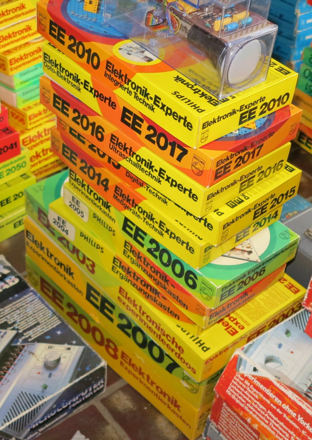
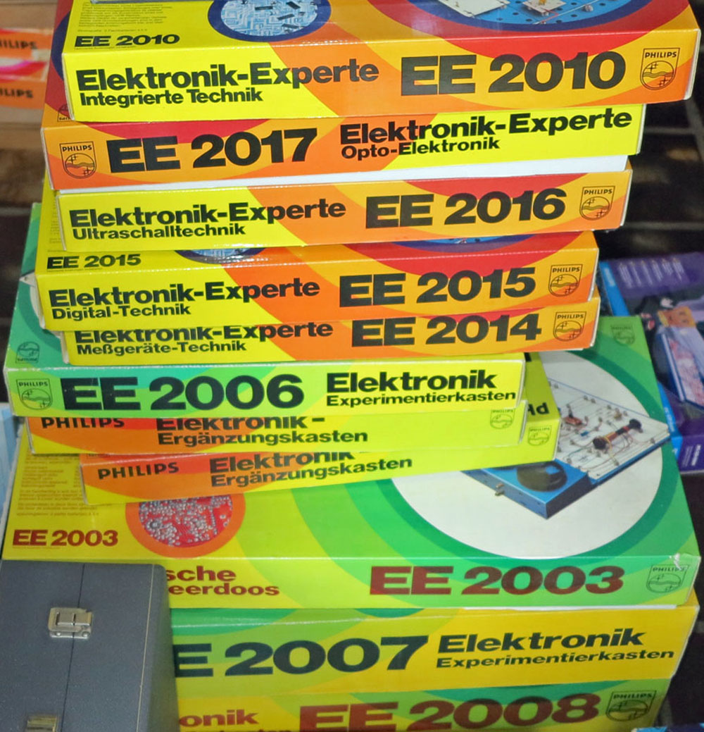
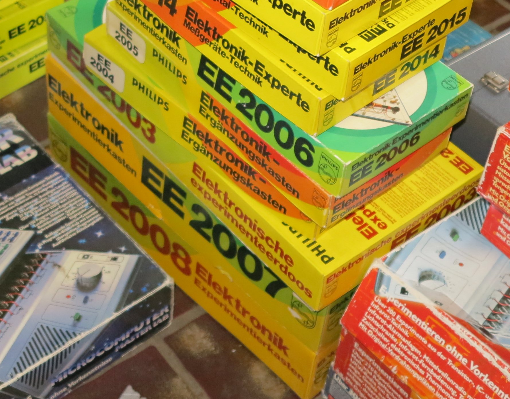
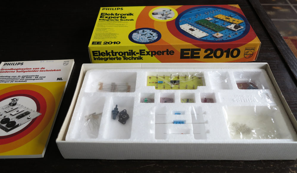
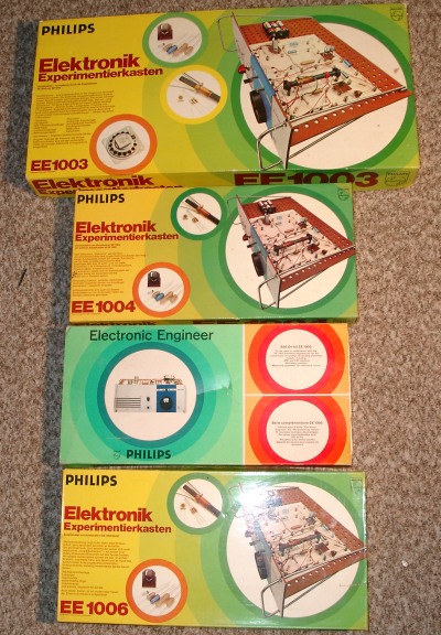
After so many years, it is very interesting to read the Instructionbook again through new eyes. The smartestthing I picked up is the design of the Radio Receiver (circuits C1, C2, C3)- it is a reflex design, which saves having to use an extra transistor – the first stage AF116 is both a Radio Frequency and Audio Frequency amplifier – clever ! I find this website and Tor Gjerde’s website to be the most interesting, as they both have some details on the EE20. However, I see that the EE1000/2000/3000 Series of kits followed on from the EE20, with many improvements, the most obvious one being the change from germanium PNP to the more modern silicon NPN transistors. Just for fun, I think I will revise the EE20 circuits to use silicon NPN transistors – and this time I will know which way round to connect the batteries 🙂
I do not recall seeing any of these later kits in South Africa – as I am sure I would have bought one if they had been available. However, I think the later kits were greatly influenced by the earlier EE5/10, and EE8/20 series, which is probably where Philips made their mark. I think that Philips as a company was extremely far-sighted in developing their range of kits, as I am sure it provided the initial spark in many young teenagers, like myself, to decide on electronics as a career.
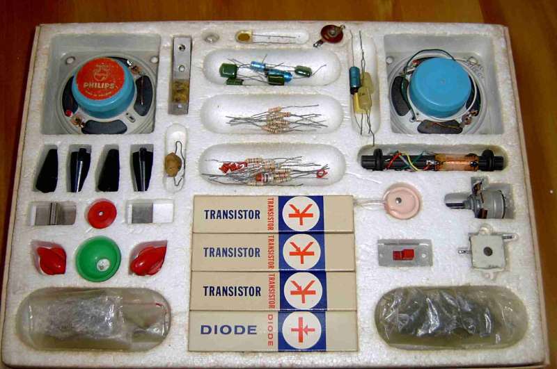
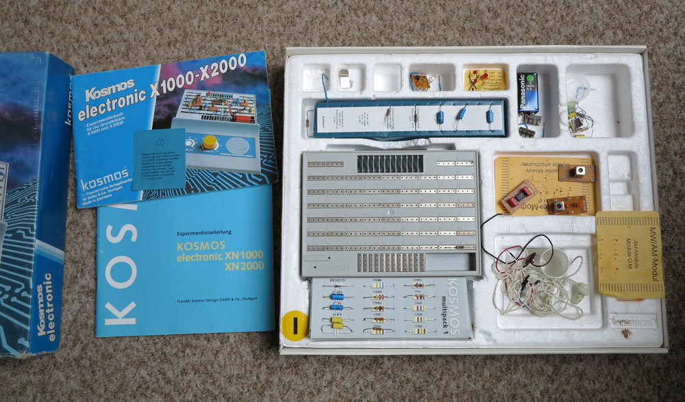
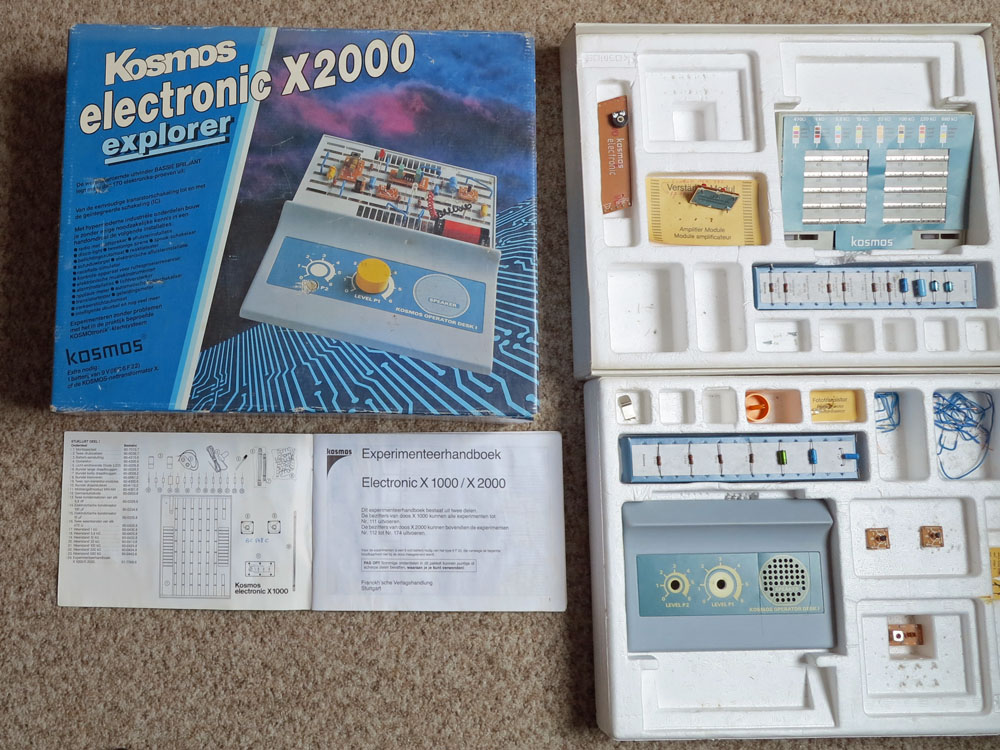
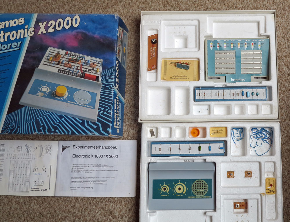
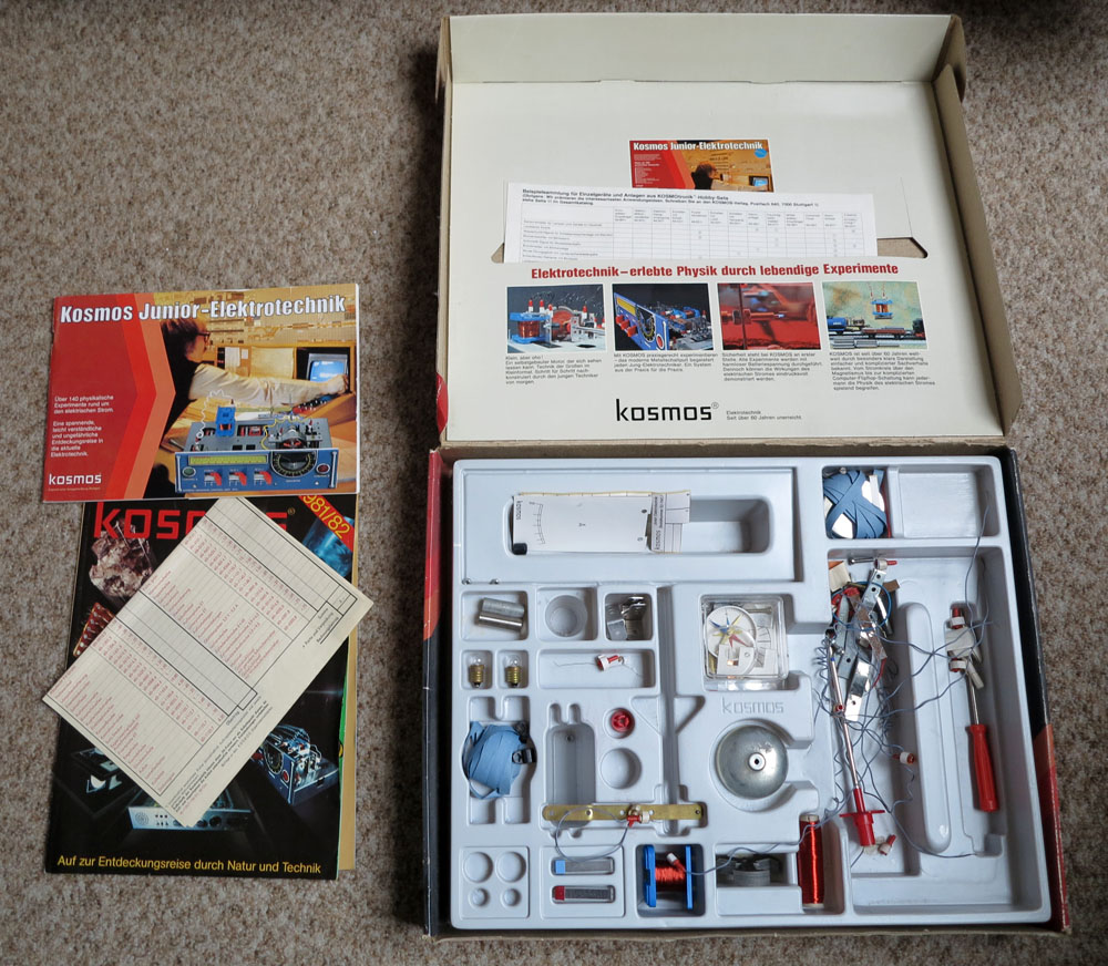
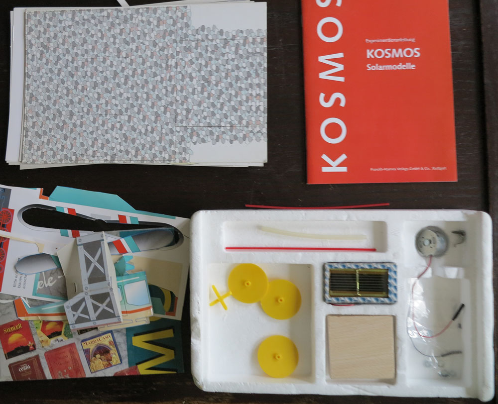
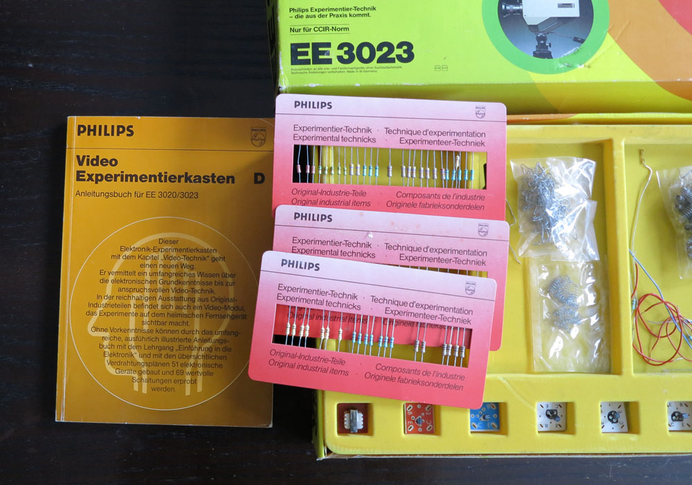
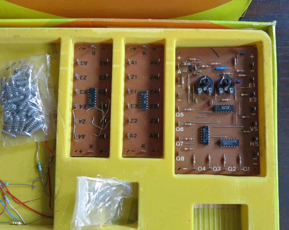
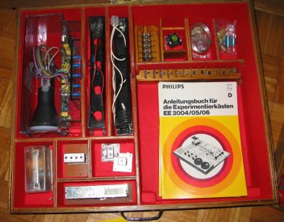
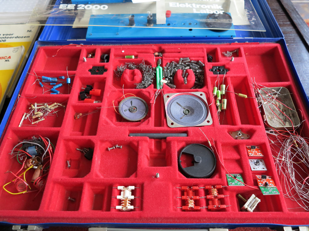
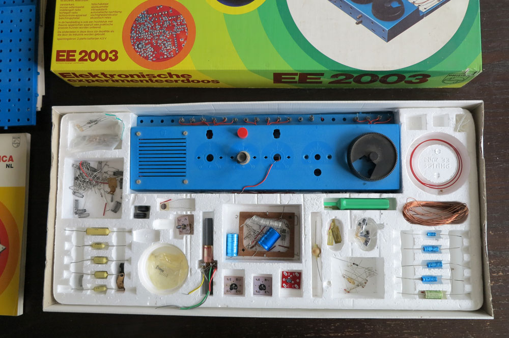
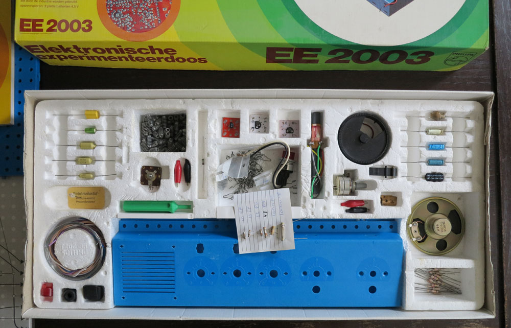
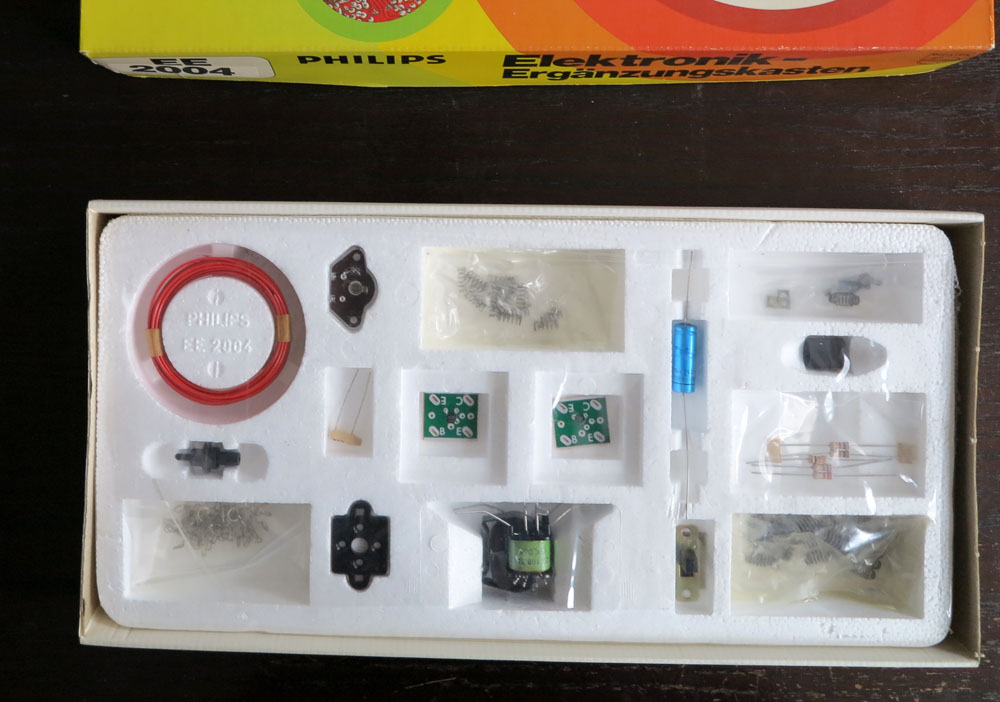
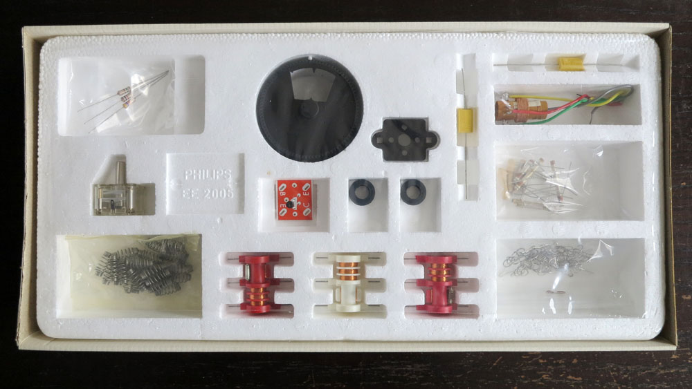
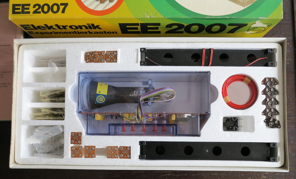
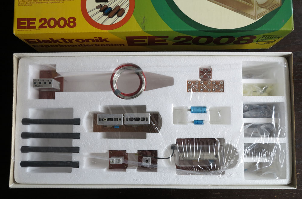
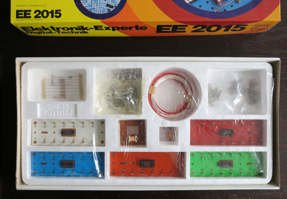
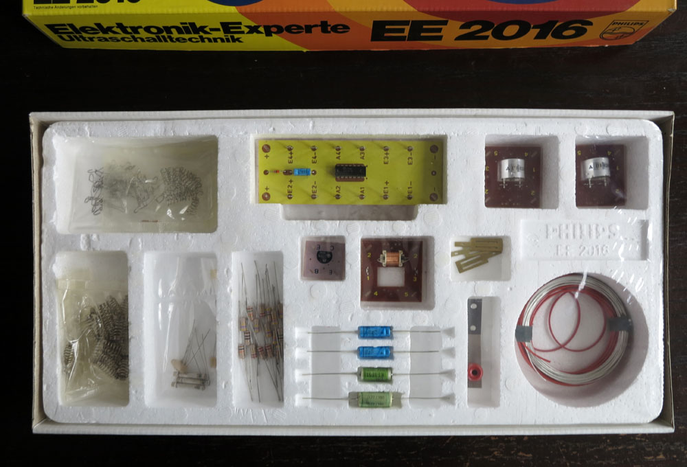
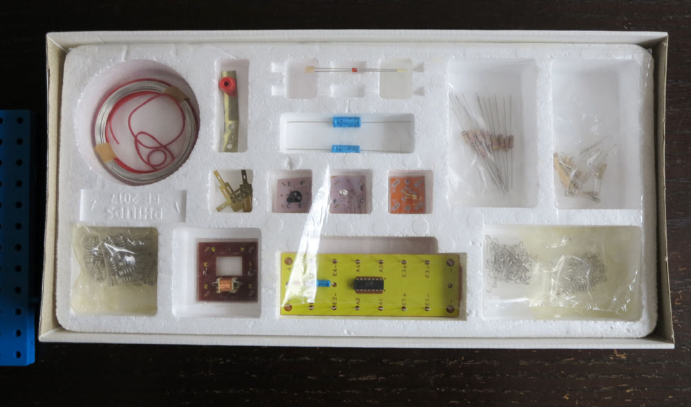
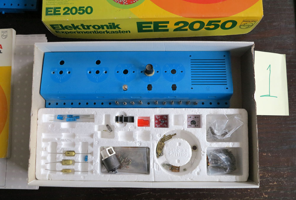
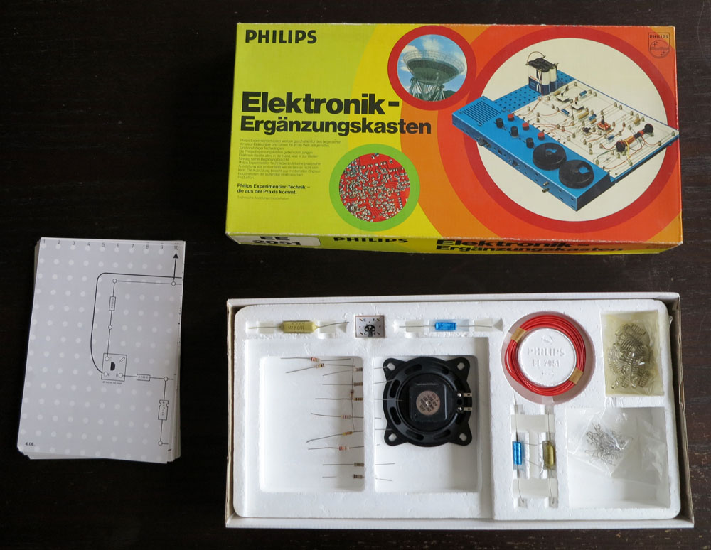
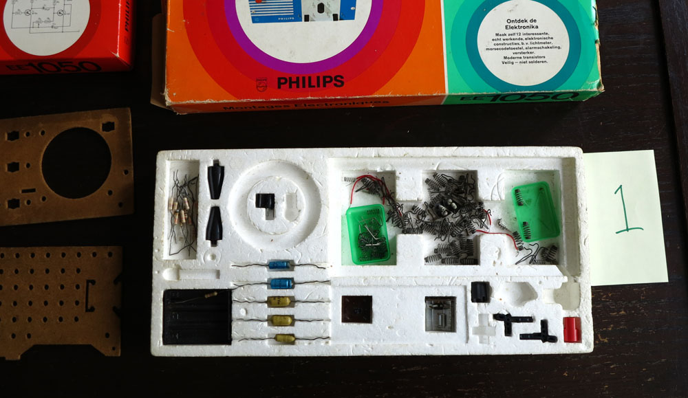
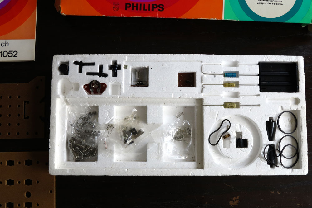
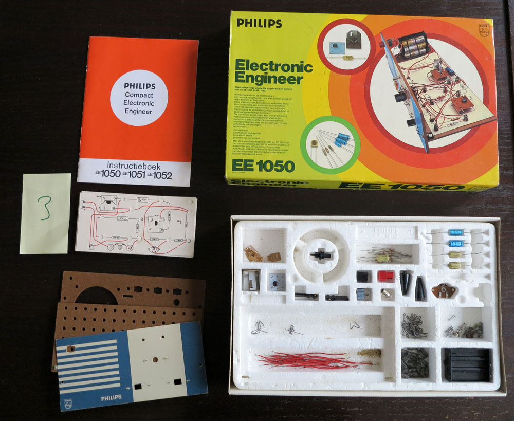
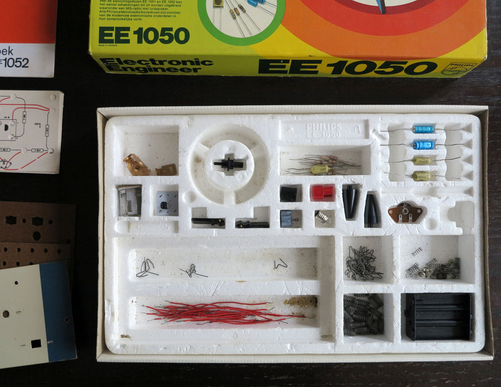
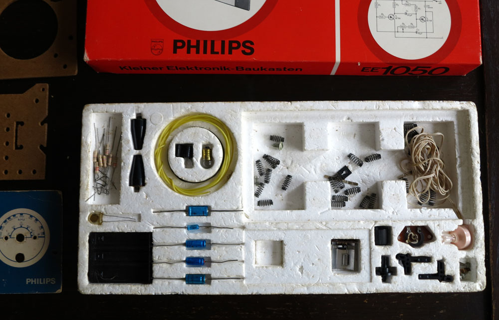
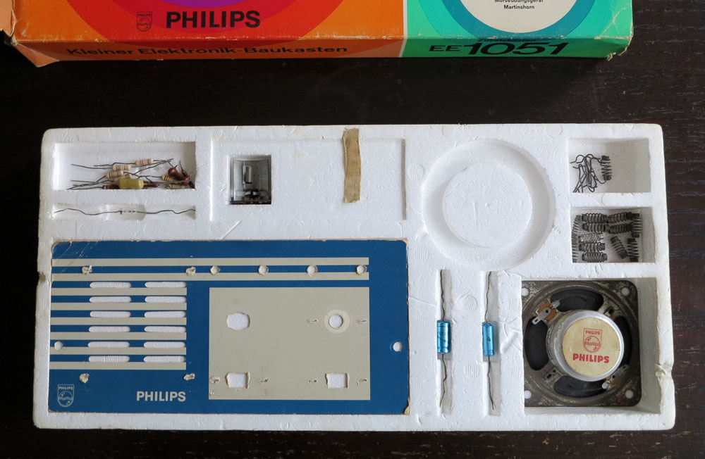
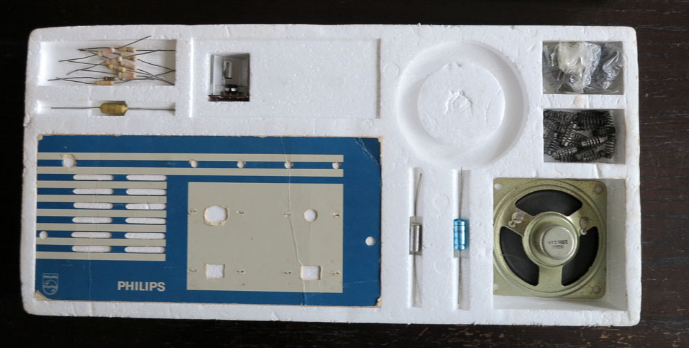
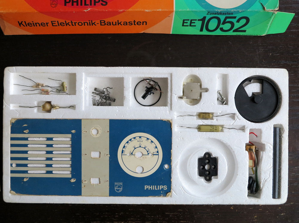
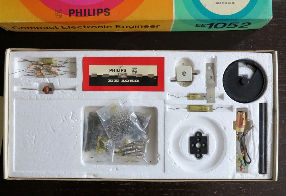
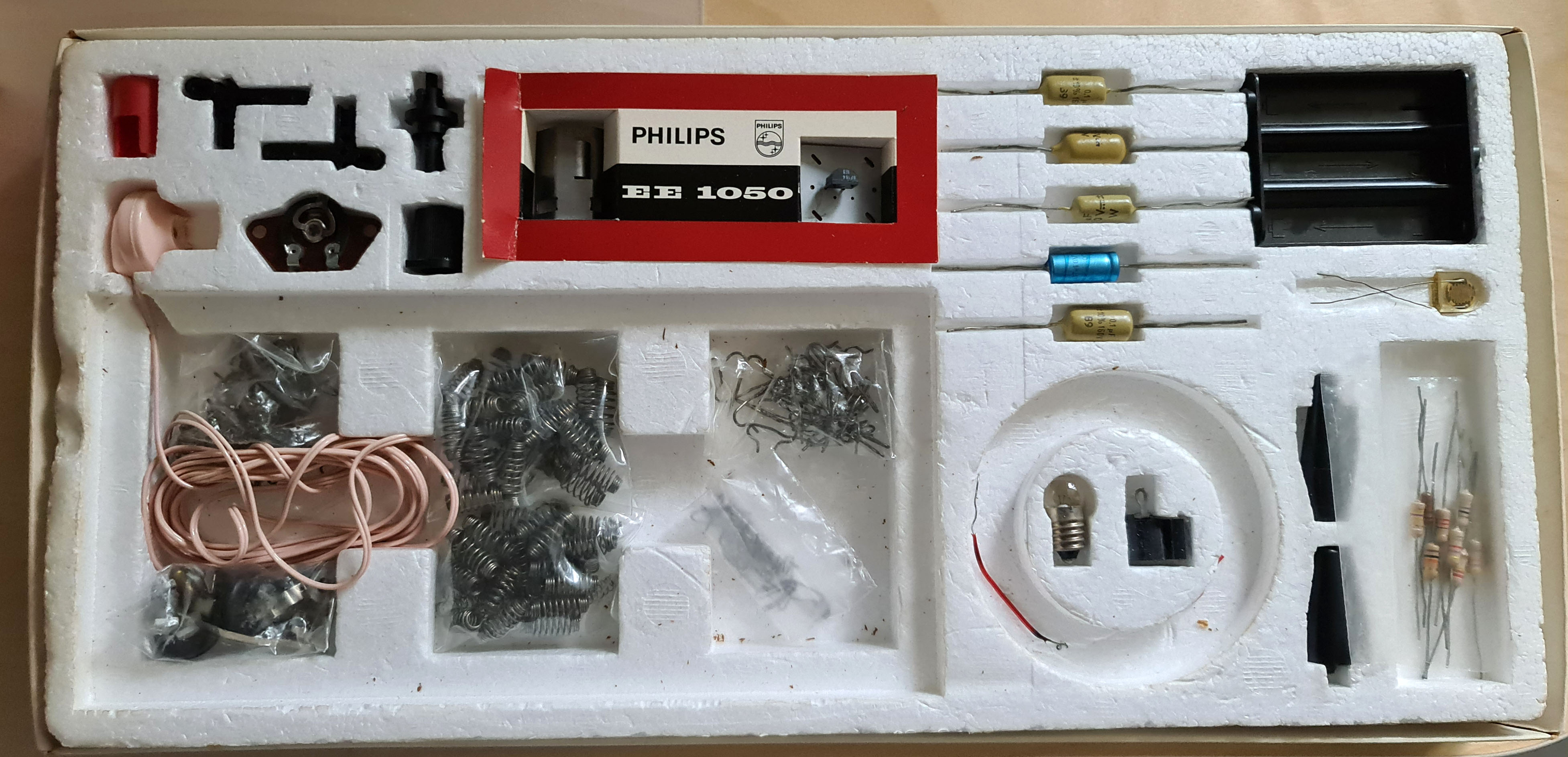
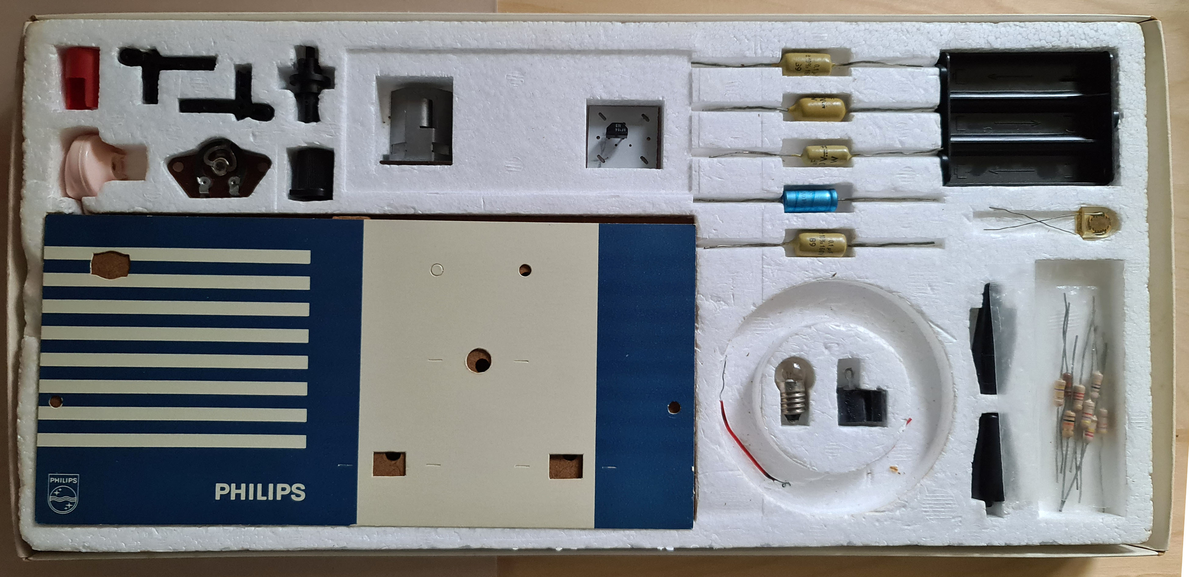
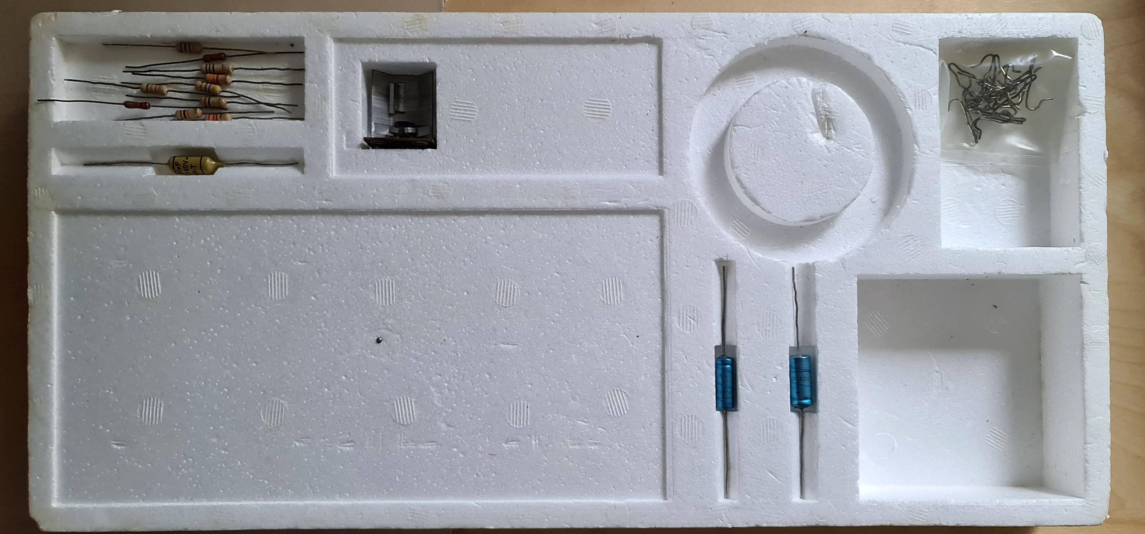
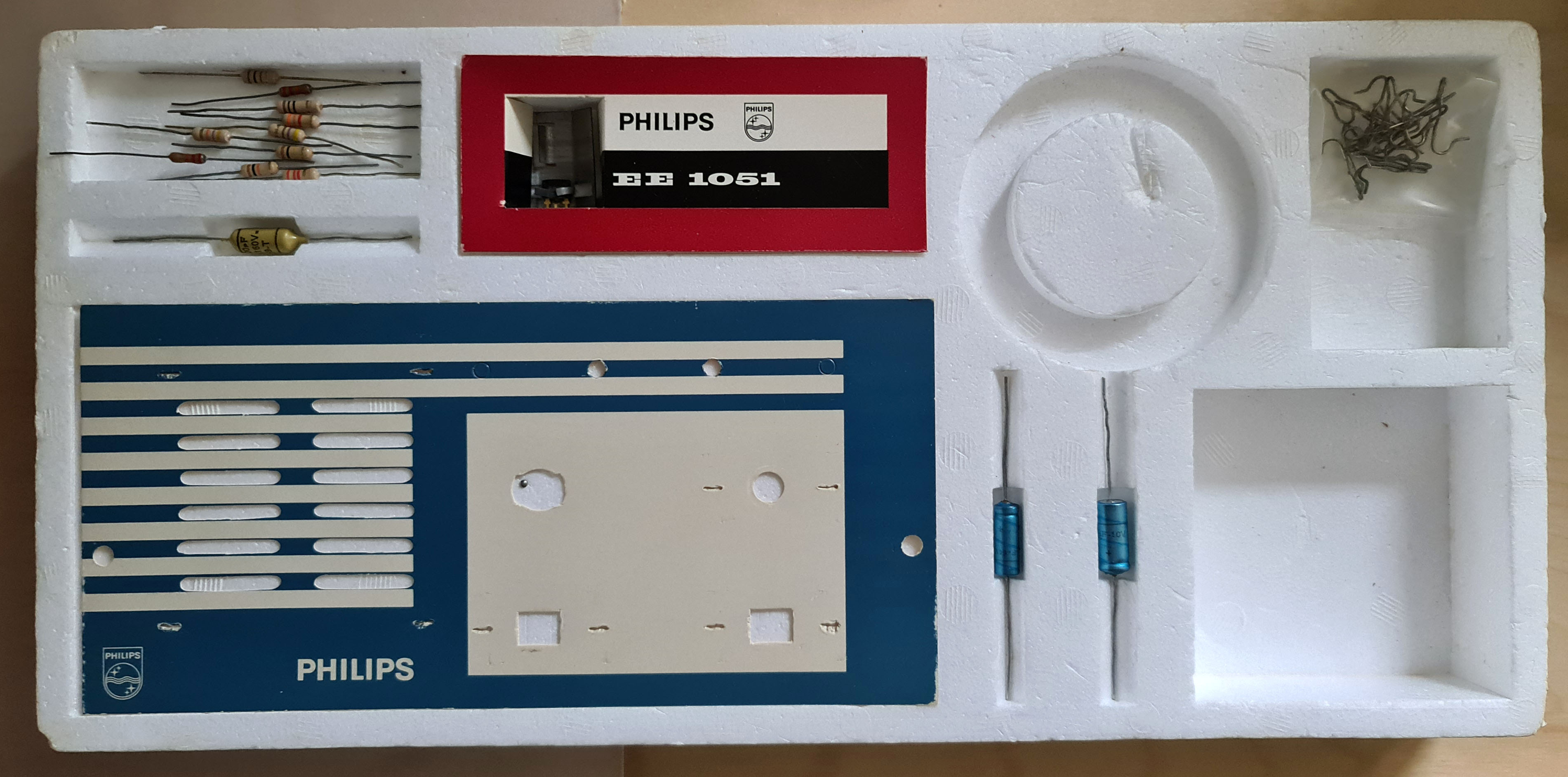
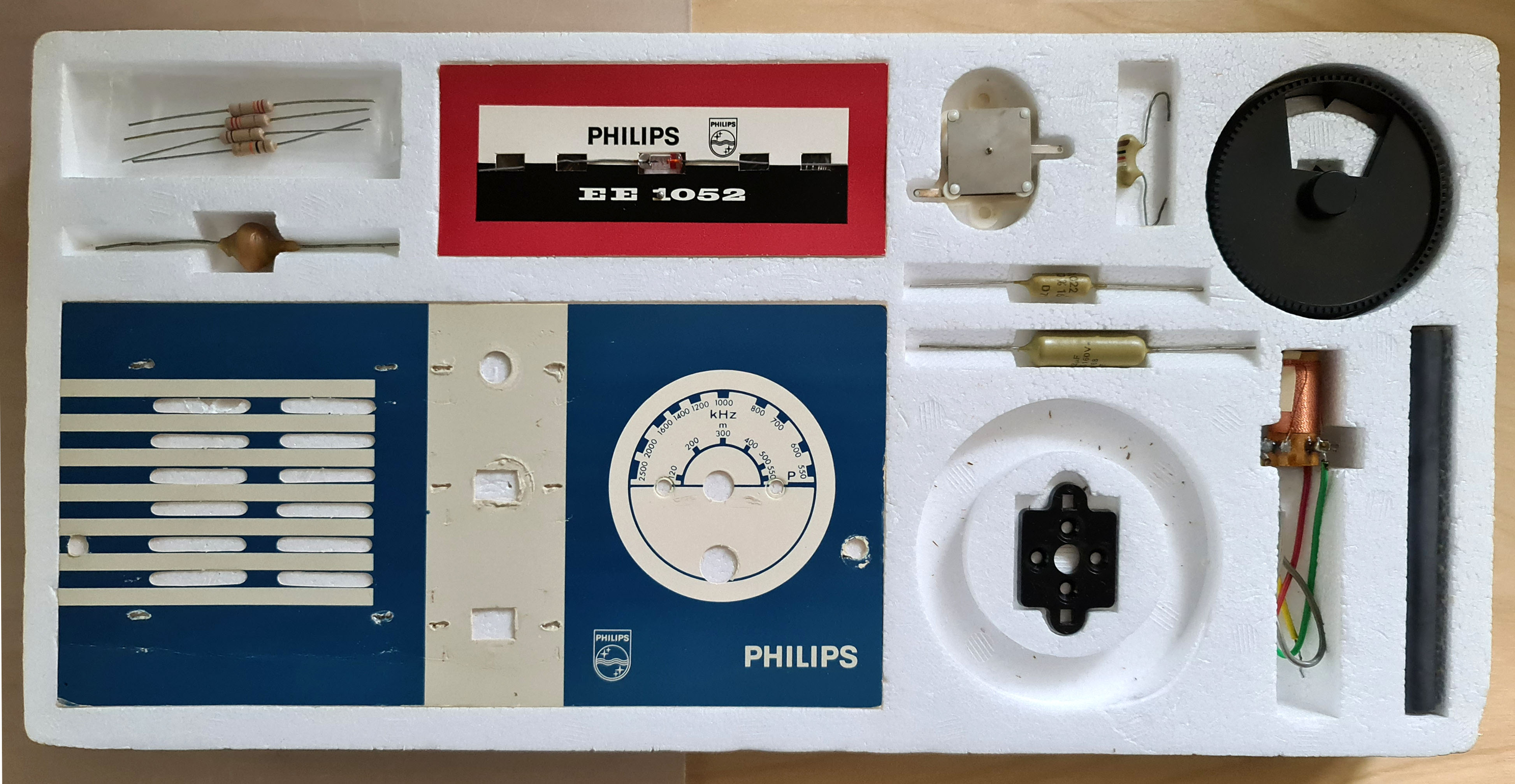
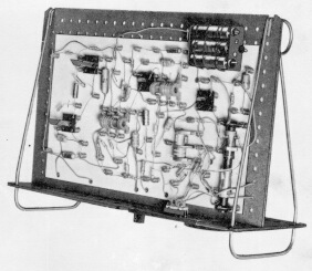
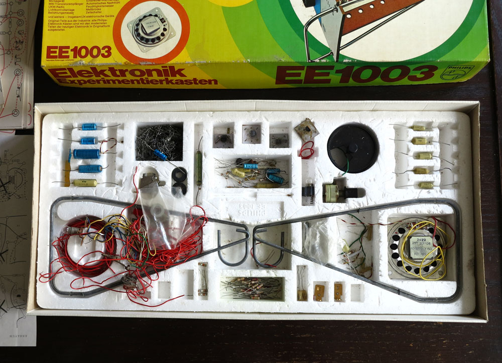
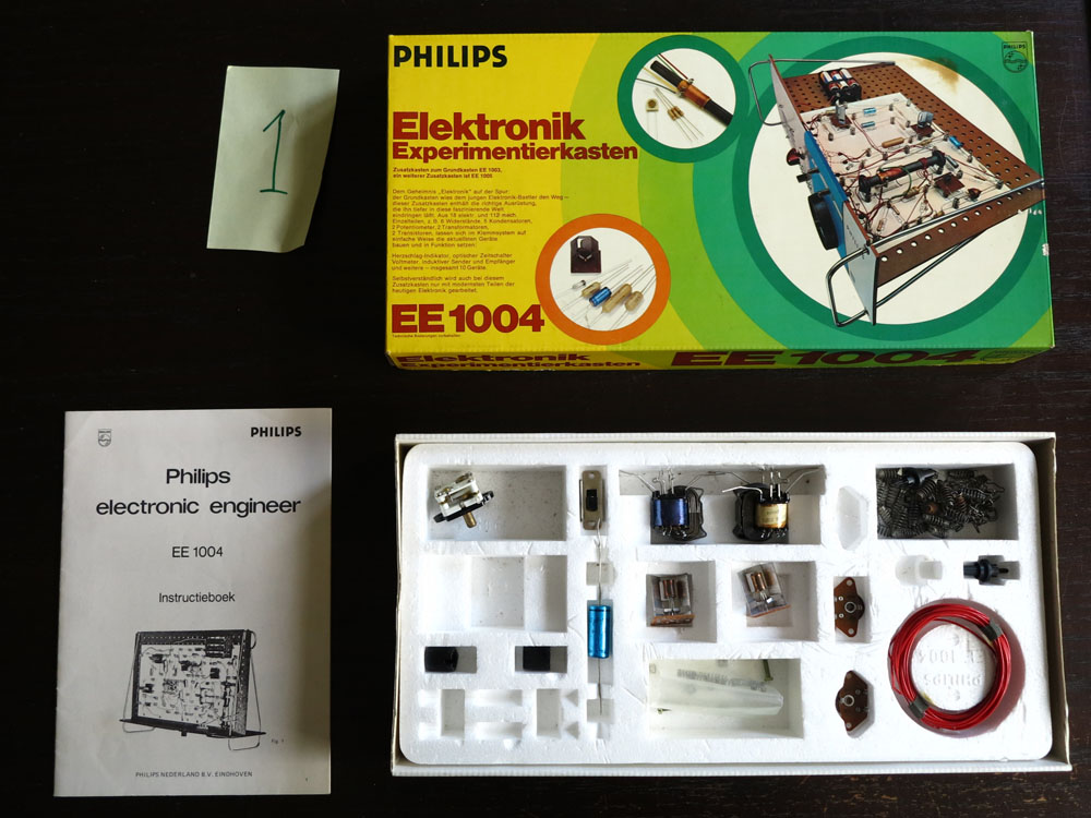
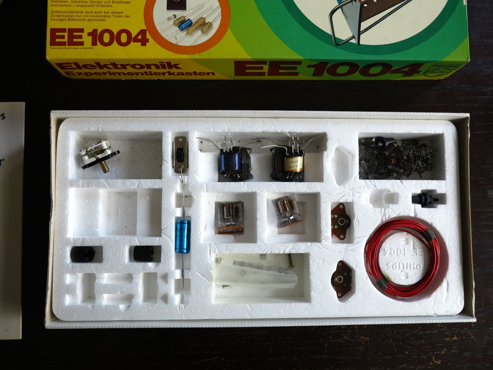
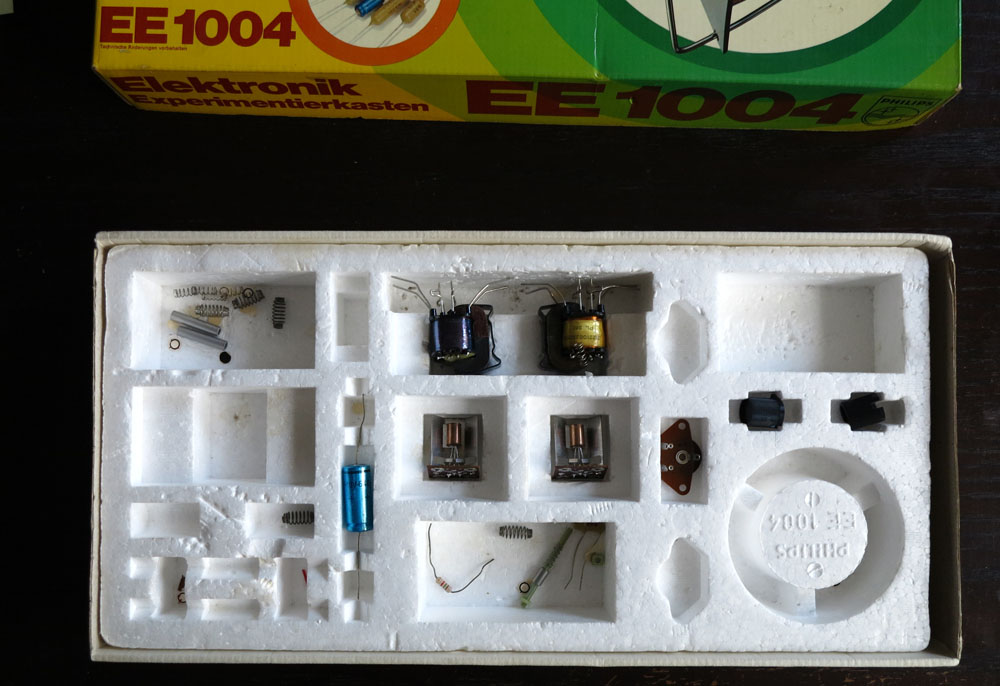
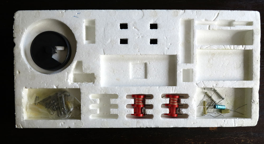
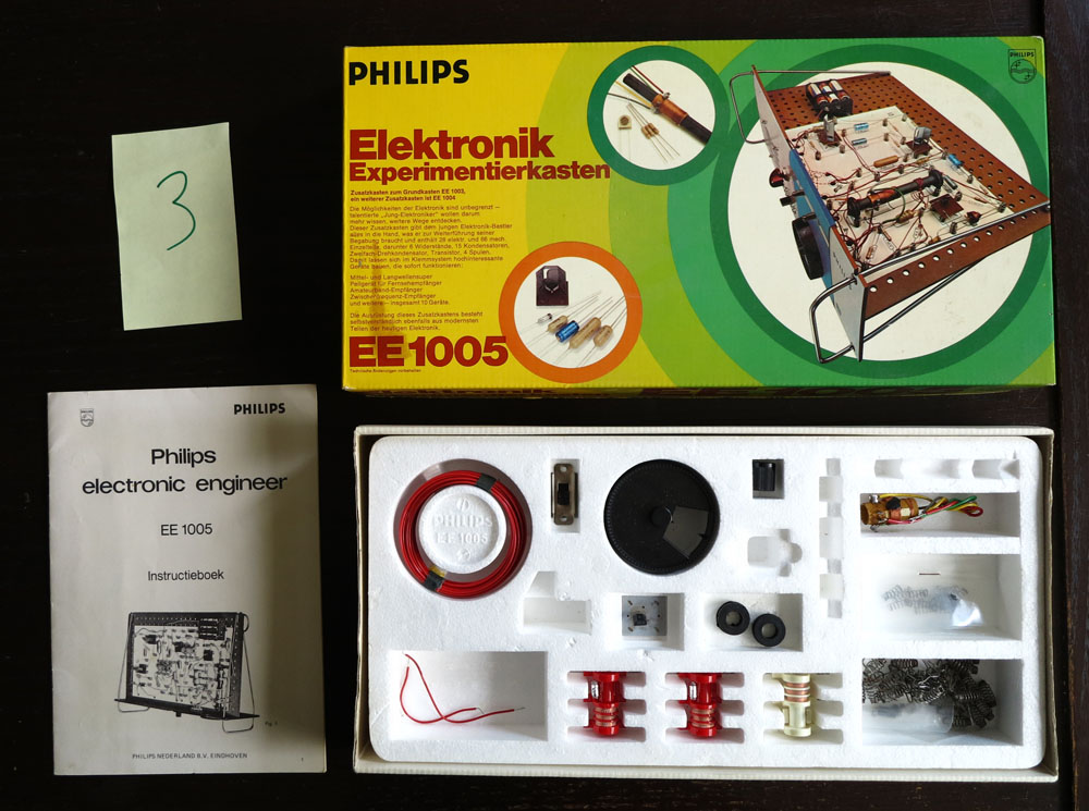
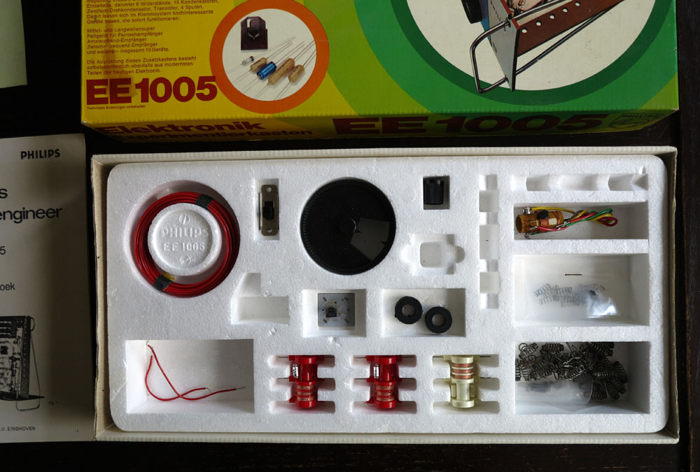
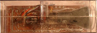
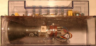
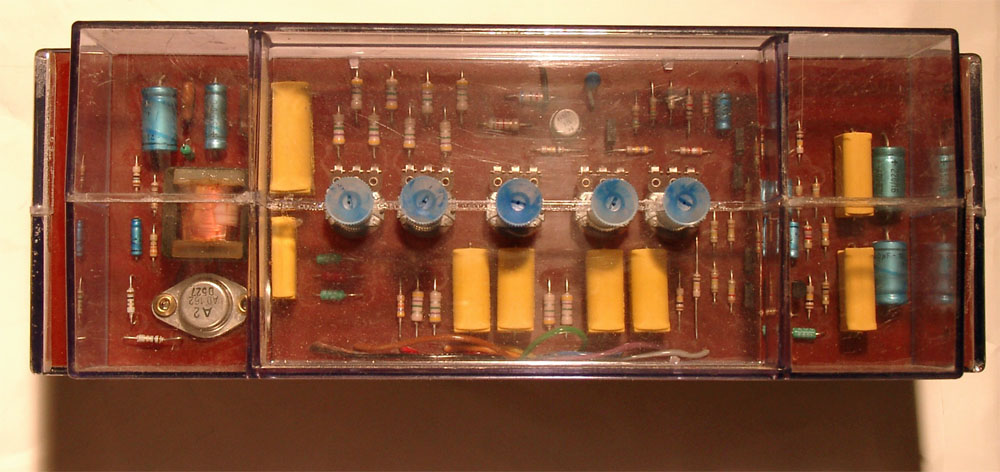
Close-up of all the components
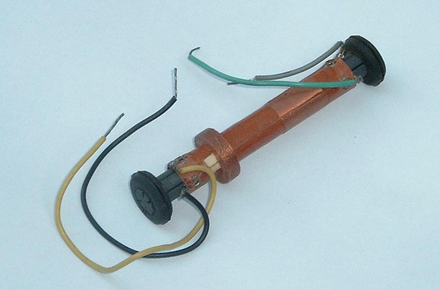
I still have some of the original Philips polyester and electrolytic capacitors, but all the resistors have long since been replaced; I actually still have most of the original resistors, but with frequent handling, the colour bands got very dark (eg red and green started to look like brown !), so these were replaced, as resistors are quite cheap ! All the major components are still the Philips originals ie potentiometer, tuning capacitor, ferrite rod antenna, one of the speakers, earpiece, LDR, switch, knobs, heatsinks, metal plates, choke coil, baseboard, circuit templates and Instructionbook. The speaker on the left, with the Philips label, is original, but the one on the right, with no label, is a replacement, but is a genuine Philips part, which I purchased from Philips here in South Africa. Of course, ALL the transistors have been replaced several times, mainly due to accidents when I started to experiment with my own circuits ! However, the OA79 diode is still the original. I found the component replaced most often was the AF116 transistor, as this seemed to blow very easily.
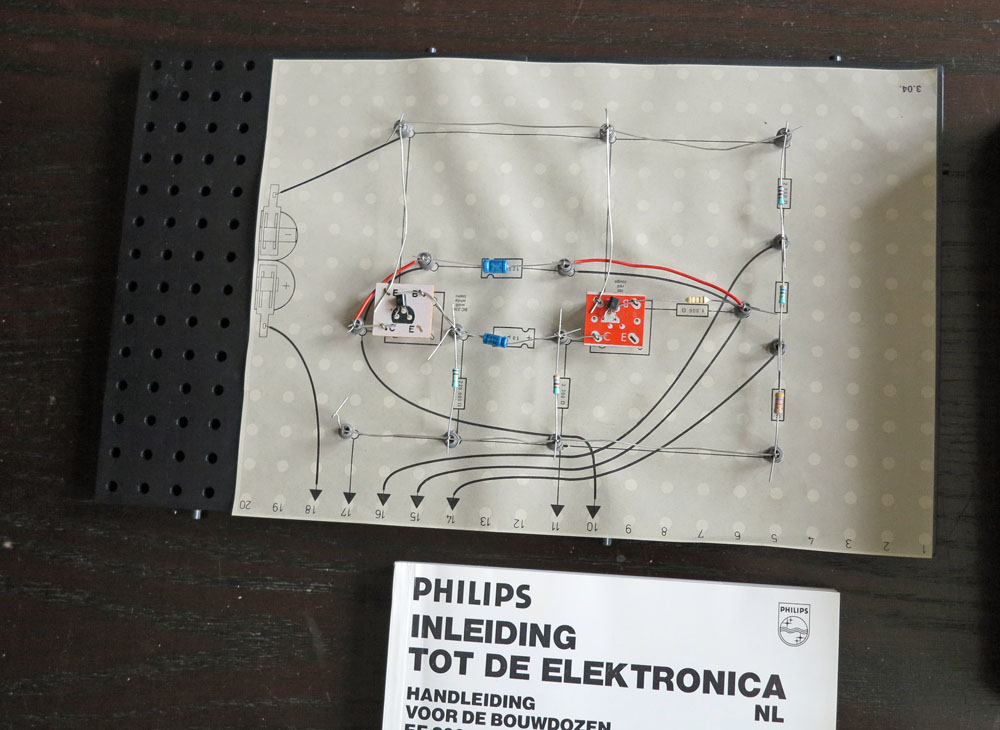
Battery polarity incorrectly indicated in early EE20 Instruction book
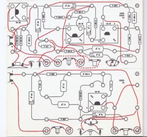
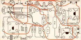
The first figure is a scan of page 23 of my own paper copy of the EE20 Instruction book, purchased in 1965. I have annotated the figure to indicate that the batteries are connected the wrong way round in the photograph. All the photos throughout my copy of the book indicate incorrect polarity just like this one.
On the back cover of my paper Instruction book, in small print at the bottom, is printed:-
Copyright N.V. Philips’ Gloeilampenfabrieken – Eindhoven – The Netherlands – 1965
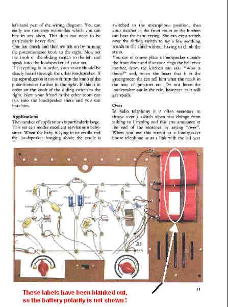
The figure above is the same page extracted from the pdf document in Tor Gjerde’s Library, which has the battery polarity blanked out. On the last page of this pdf Instructionbook the same small text appears as on my paper copy, but the publication date is 1966, and the part number of the book is completely different. My older paper copy, and the newer pdf file also have small differences in other places.
The later publication date of the pdf Instructionbook suggests that Philips picked up the error and very quickly published an updated edition in 1966 (Torhas told me that there were blank stickers placed over the battery polarity in the paper copy he scanned). Throughout the rest of the book, wherever battery polarity is discussed in the text or indicated in the blue schematic diagrammes, the polarity is correct – only the photographs are incorrect. These could therefore not have been working models as I had assumed – ie they are merely “dummies” for the photographs !
Any engineer, such as myself, would immediately recognize this as an obvious error, but when I was 11 years old, I did not know what I know today ! To the uninformed, this is quite a serious error, but after 40 years, I have forgiven Philips … this is, after all, how we learn !!


