Microsoft’s 6502 BASIC is now Open Source, and that includes KB9 or as it is officially called:
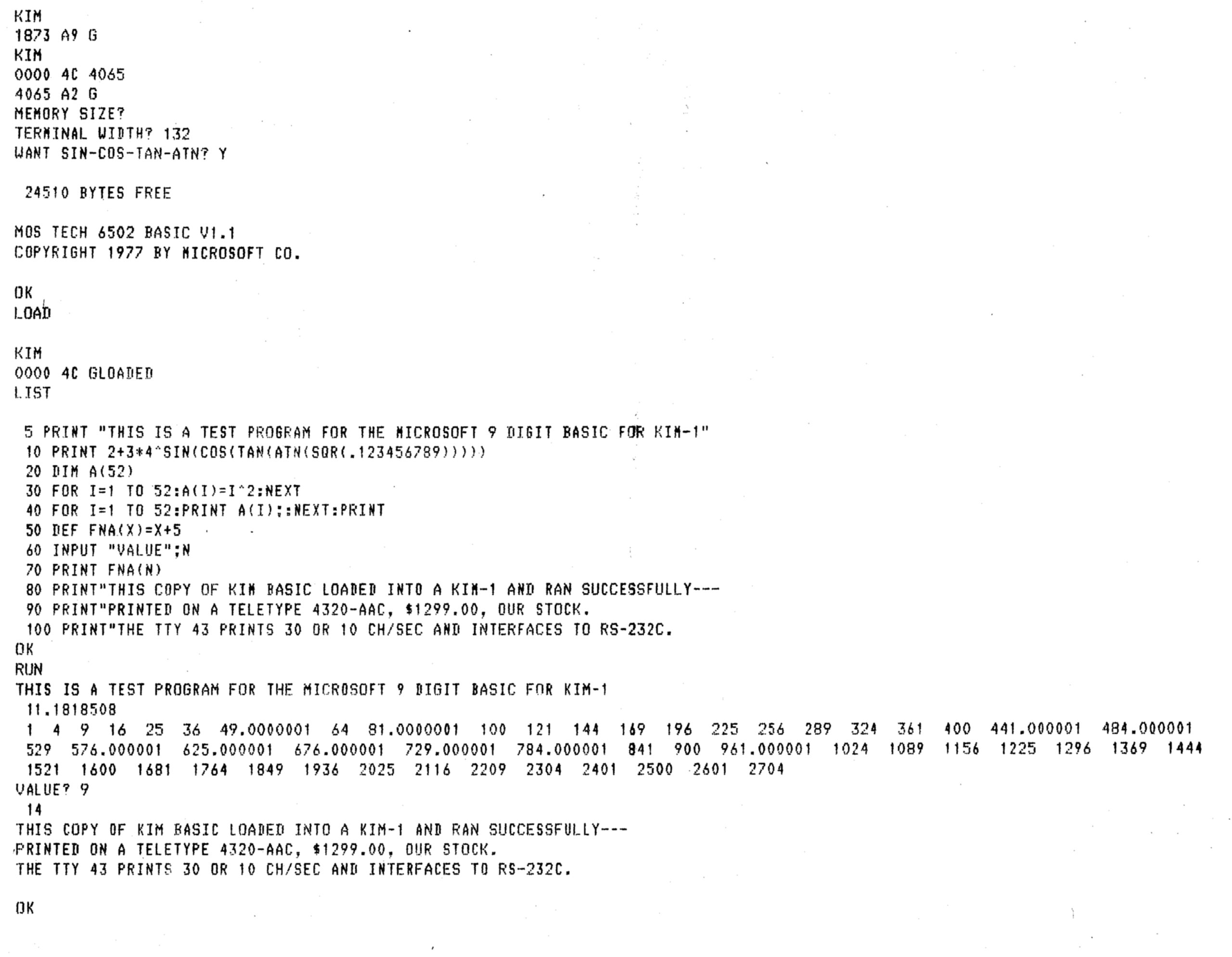
MOS TECH 6502 BASIC V1.1
COPYRIGHT 1977 BY MICROSOFT
Microsoft’s 6502 BASIC is now Open Source
“Now, for the first time, this influential 6502 version is truly yours to explore, modify, and share.”
This means that we are allowed to distribute and modify KB9 and derivates without breaking licenses!
Also see the pagetable post from 2005 that explains a lot about this source.
The license that goes with 6502 BASIC is the MIT License.
On this page you will find:
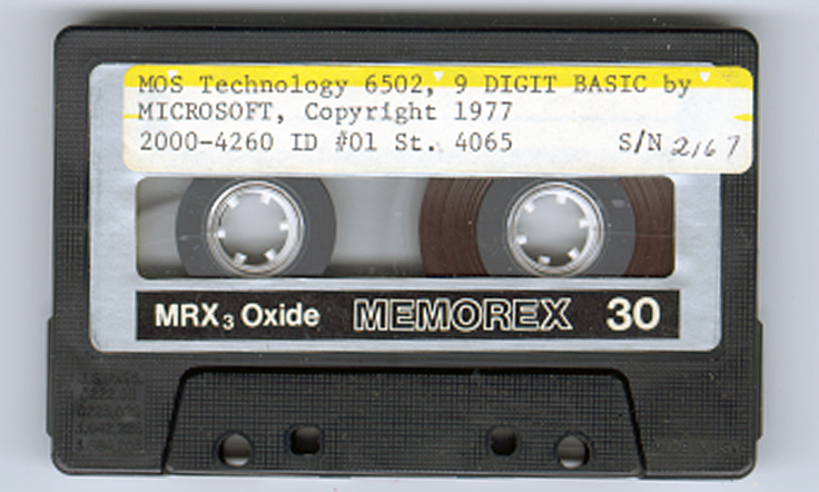
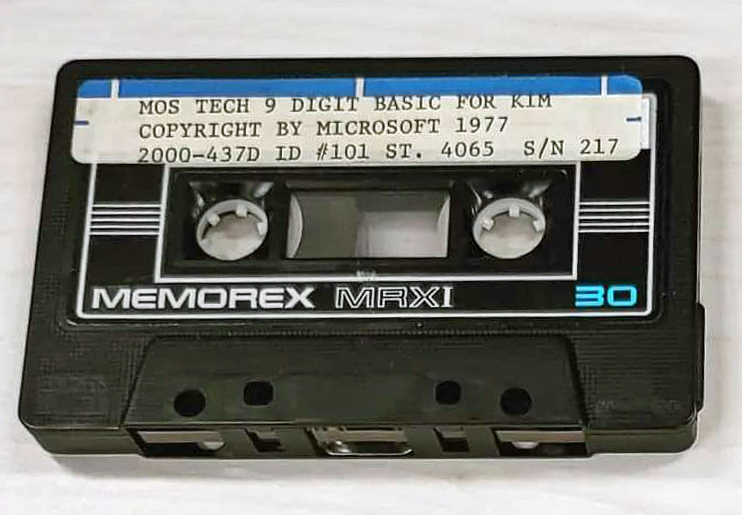
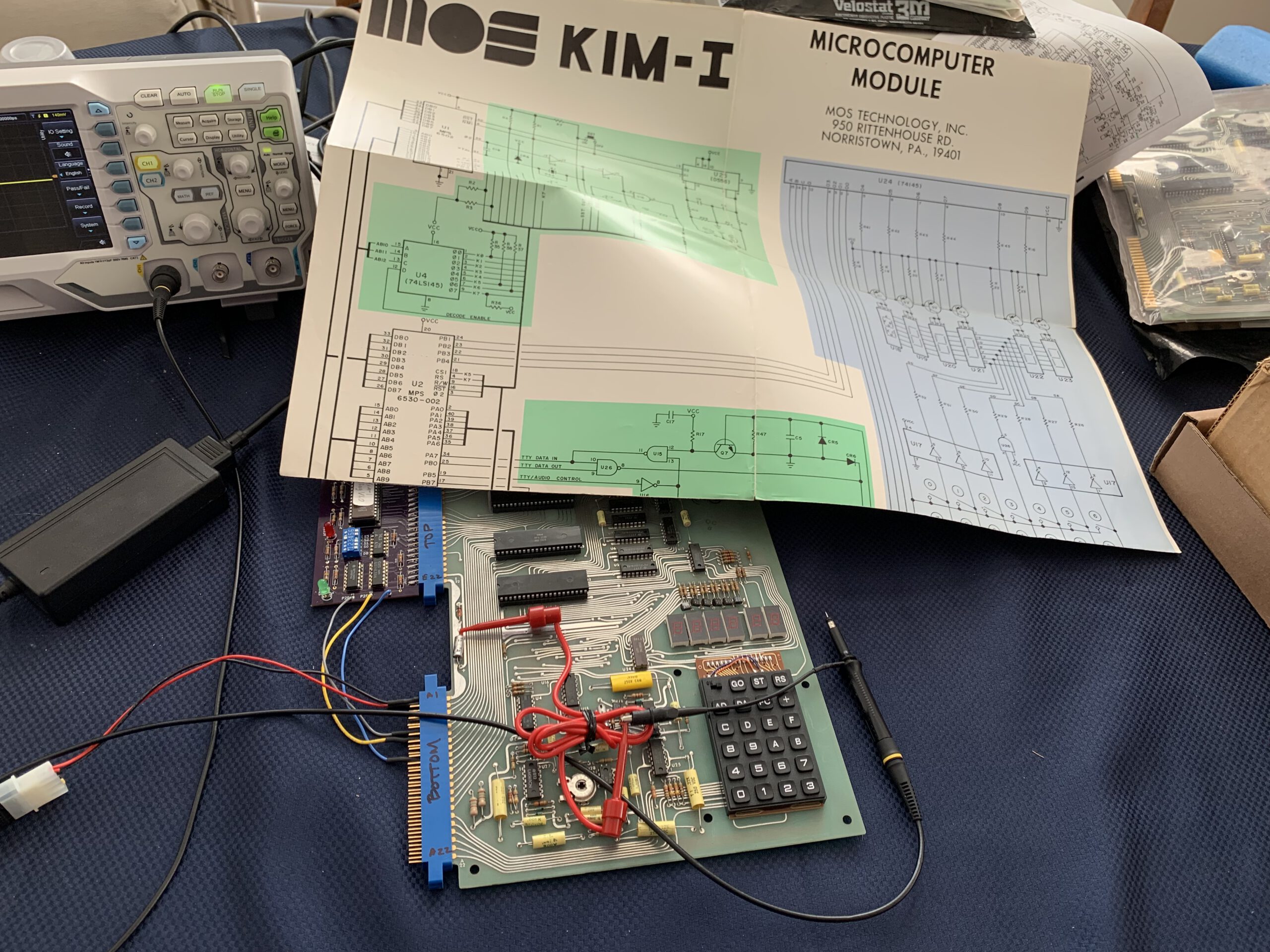
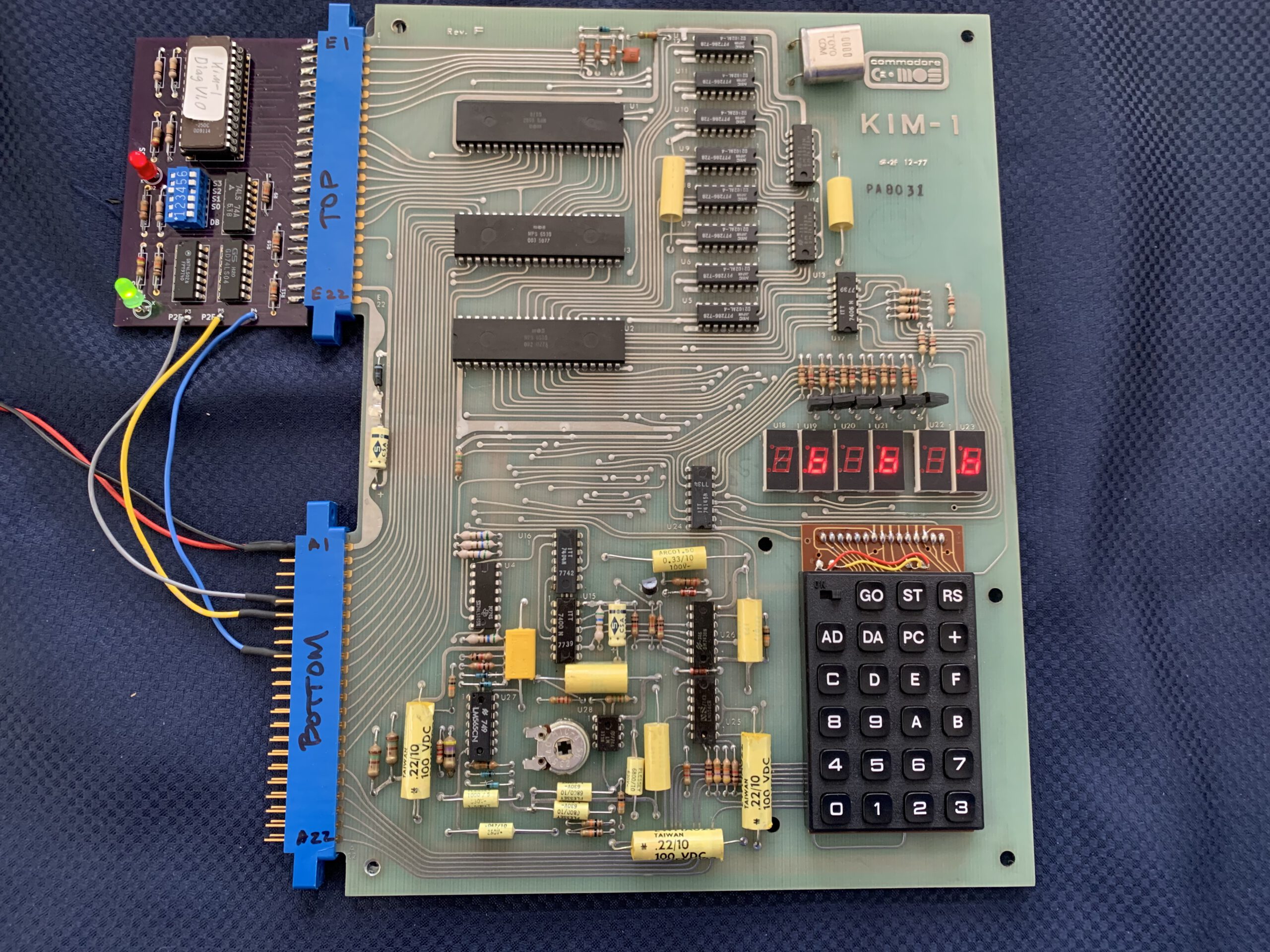
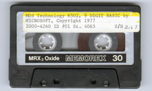
Another MOS TECH BASIC for KIM-1, lower serial number

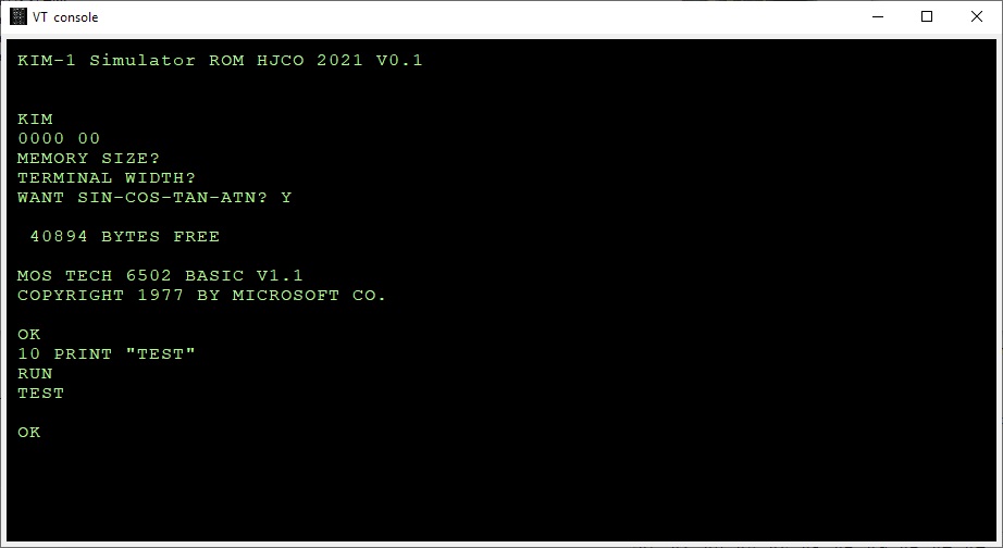

KB-9 stands for Microsoft Basic V1.1 for the KIM-1 with 9 digits precision. Actually, when you run it, it is called MOS Tech 6502 Basic v1.1 Copyright 1977 by Microsoft Co.
The ‘9’ stands for 9 digit precision floating point numbers. A KB-6 (6 digits precision) existed, but no copy ever turned up.
Downloads
Resources
Articles on KB9 in the clubmagazine KIM/6502 Kenner:
– KIM Kenner 4 Siep de Vries Evaluatie 8K Basic, test of accuracy of KB-9, Dutch
– KIM Kenner 5 Uwe Schroder, English, Some Basic problems solved
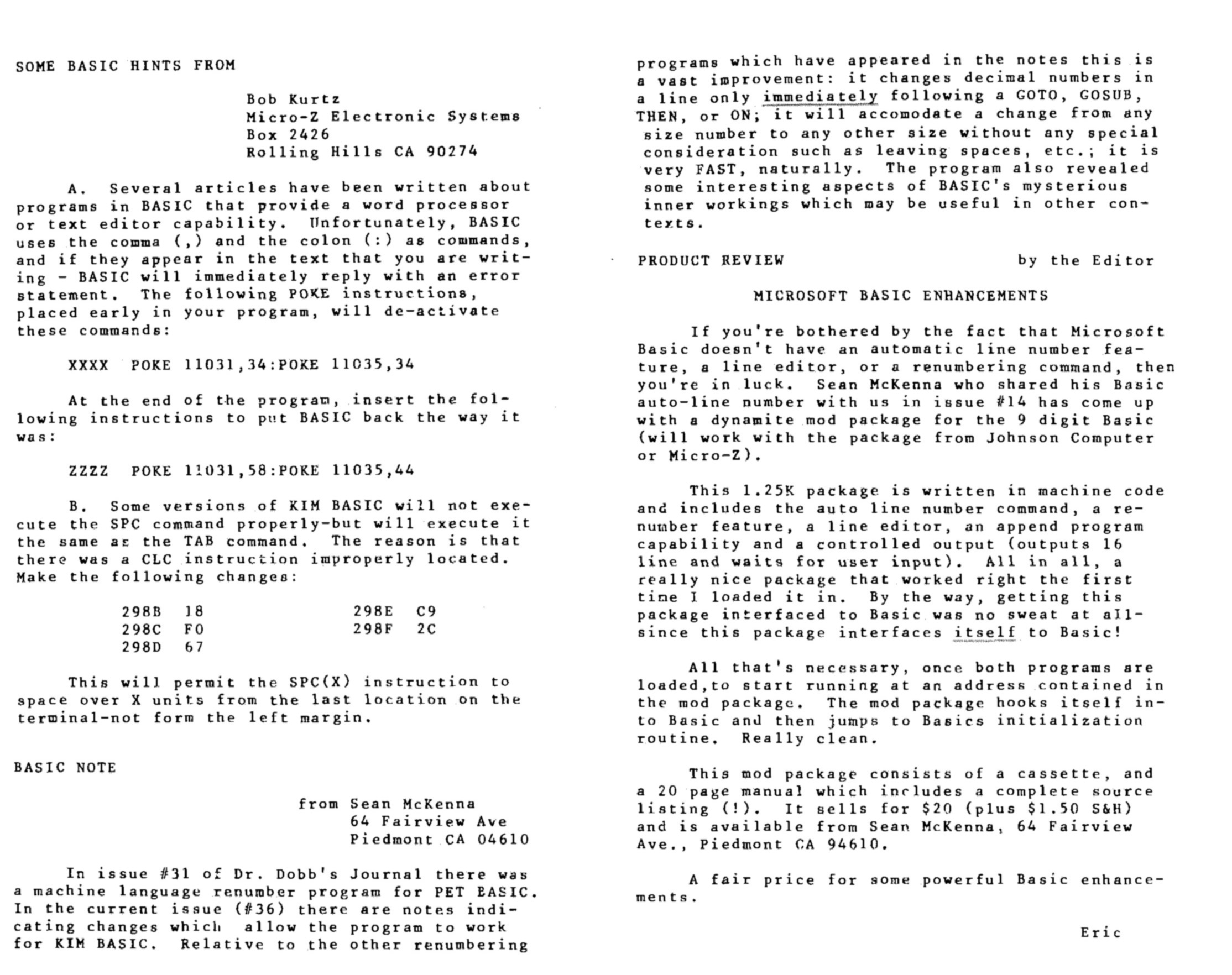
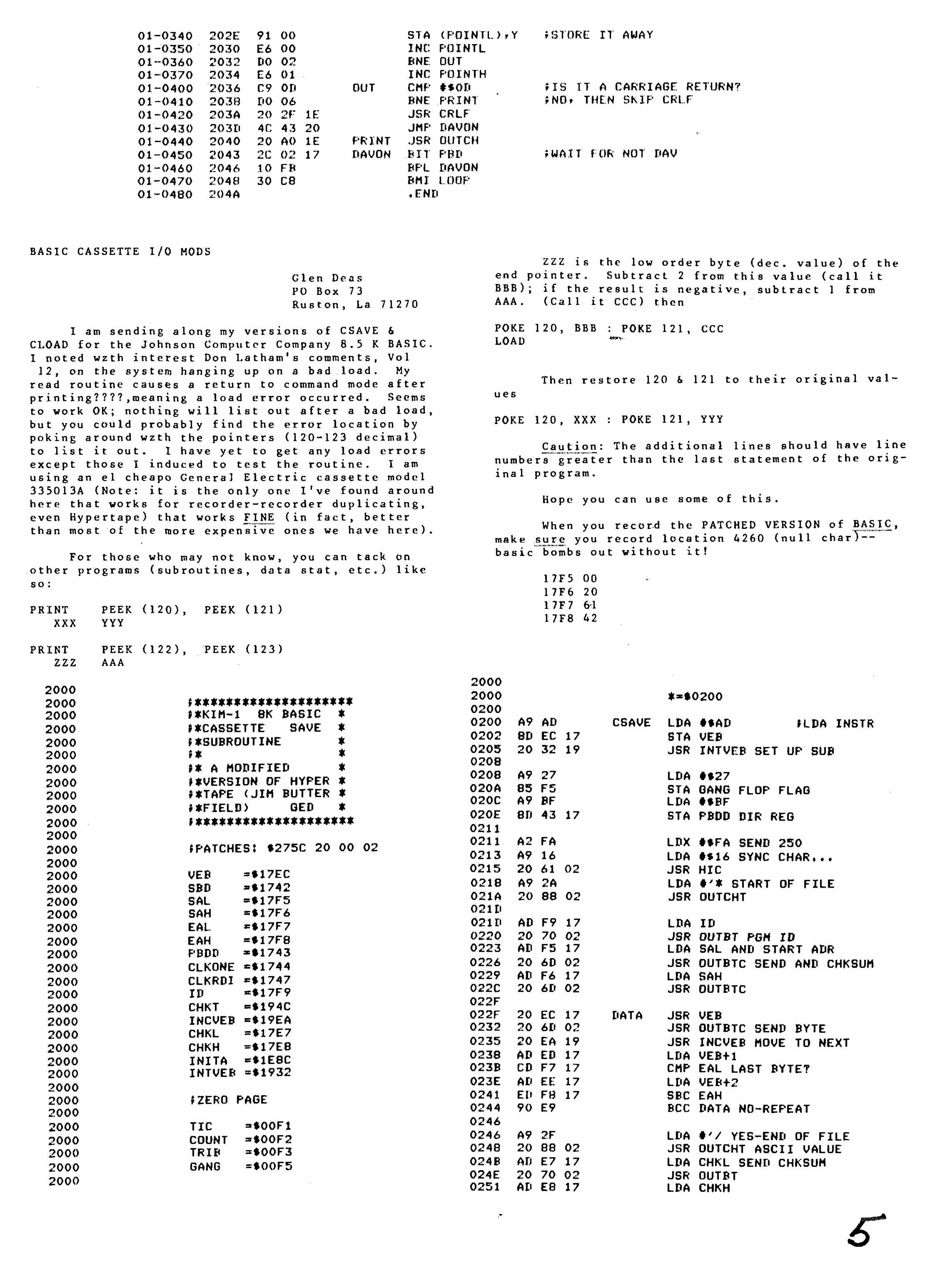
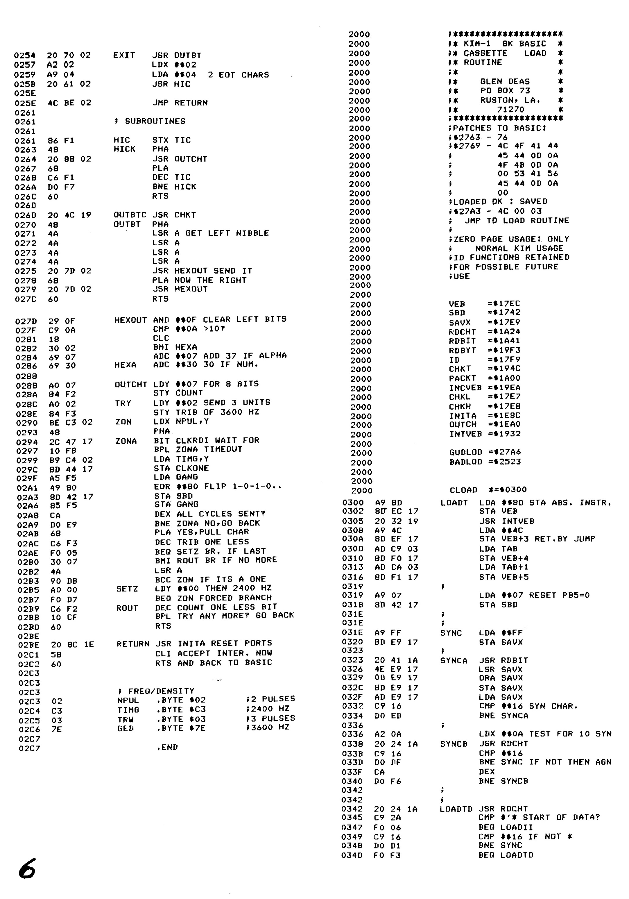
– KIM Kenner 6 S. Woldringh Patches op 8K Basic Load and Save commands
– KIM Kenner 10 p 10 Microsoft Basic, Hans Otten.
– KIM Kenner 11 p 15 S. Woldringh Patches op 8K Basic part 2
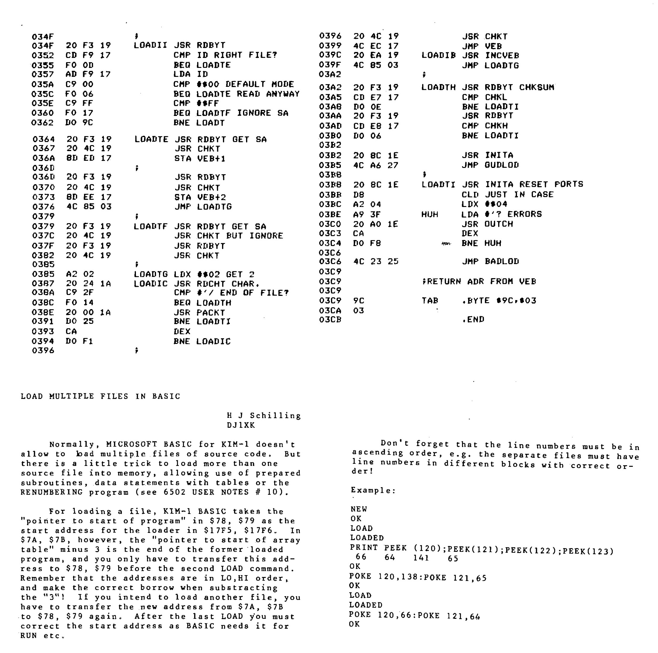
– KIM Kenner 11 p 19 W. van Gelderen Read and Write on cassette for 8K Basic
– KIM Kenner 12 p 15 Patches Microsoft Basic, Hans Otten. Trace mode Renumber
– KIM Kenner 14 p 39 Patches Microsoft Basic, Hans Otten. Calculated line numbers
– 6502 Kenner 16 p 49 Patches Microsoft Basic, W. Blonk Corrections on KIM Kenner 12
– 6502 Kenner 19 p 34 Patches Microsoft Basic, Hans Otten. Speed up Basic 10% with ROR
– 6502 Kenner 22 p 12 Patches Microsoft Basic part 1, van Nieuwenhove Koen, adapt KB-9 to Elektor Junior
– 6502 Kenner 23 p 12 Patches Microsoft Basic part 2, van Nieuwenhove Koen, adapt KB-9 to Elektor Junior
– 6502 Kenner 24 p 14 Patches Microsoft Basic part 3, van Nieuwenhove Koen, adapt KB-9 to Elektor Junior
– 6502 Kenner 25 p 6 Patches Microsoft Basic part 4, van Nieuwenhove Koen, adapt KB-9 to Elektor Junior
– 6502 Kenner 29 p 33 KB-9 Basic on Acorn SYSTEM-1
– 6502 Kenner 32 p 21 W. L. van Pelt KB-9 Basic Tokenized keywords and addresses
All the KB9 KIMKenner articles in one PDF here
Language lab section in the 6502 User Notes:
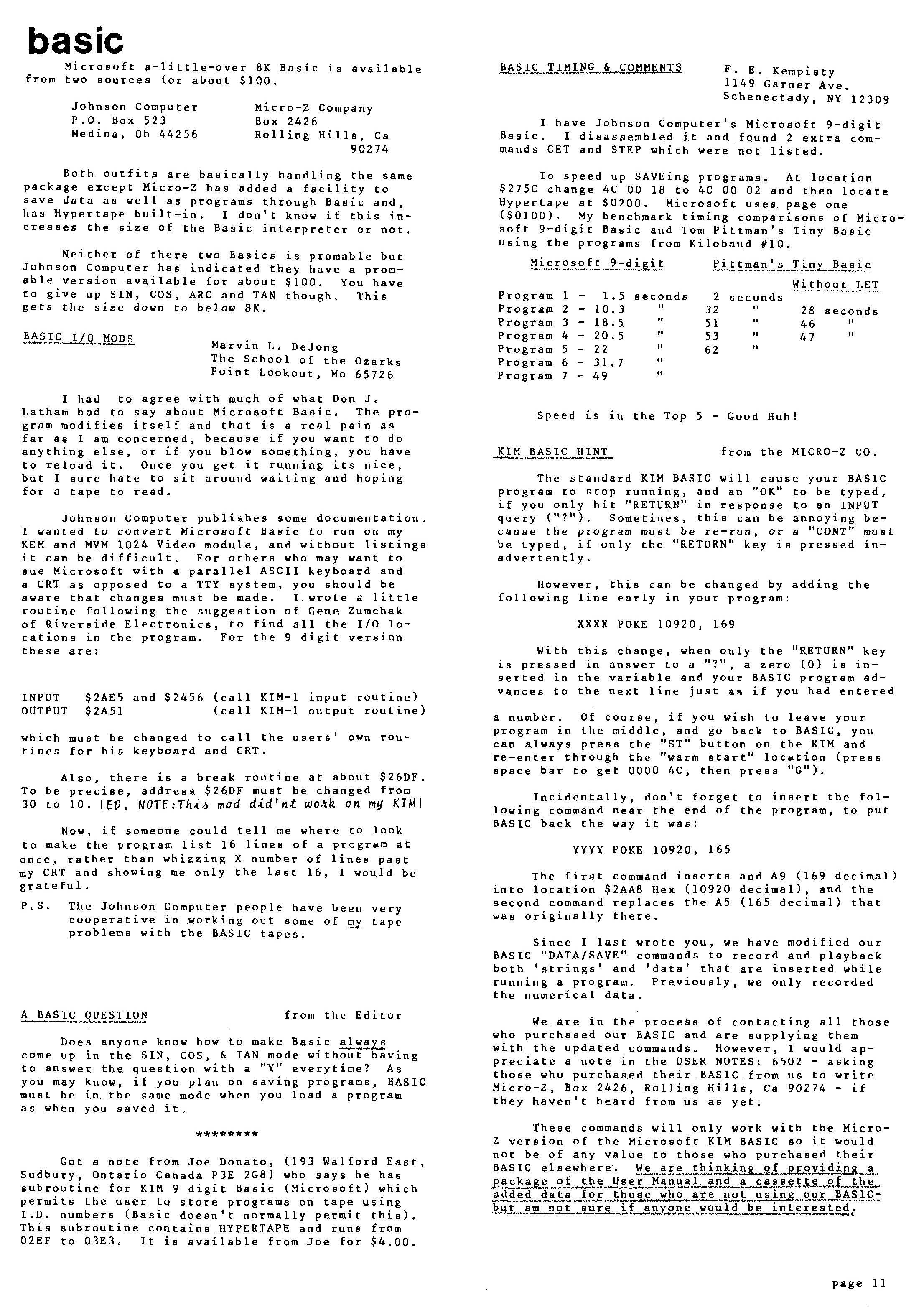
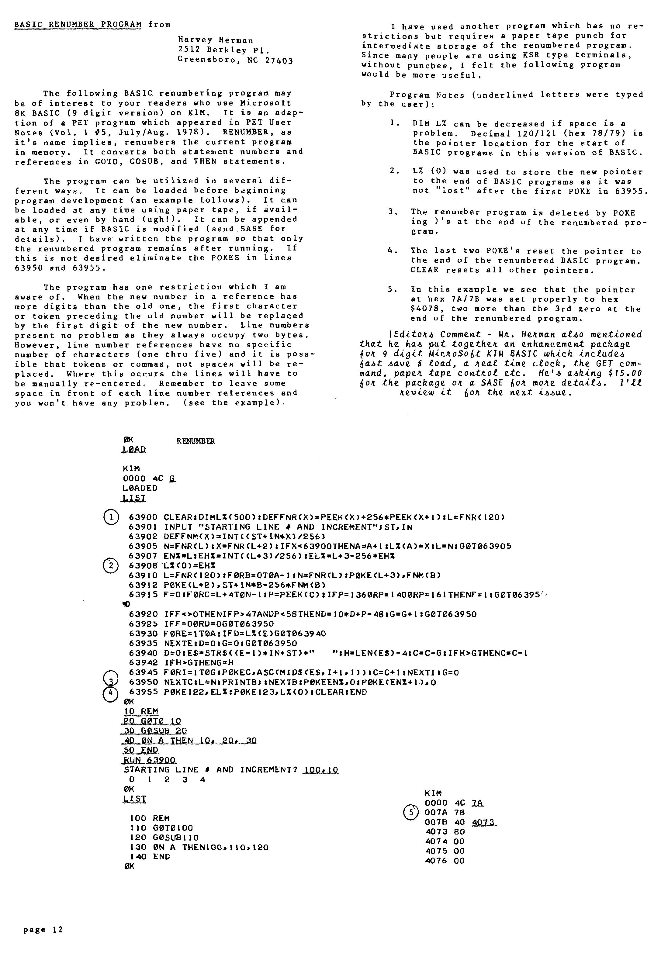
– Vol 13 Basic tips, Renumber Page 1, Page 2
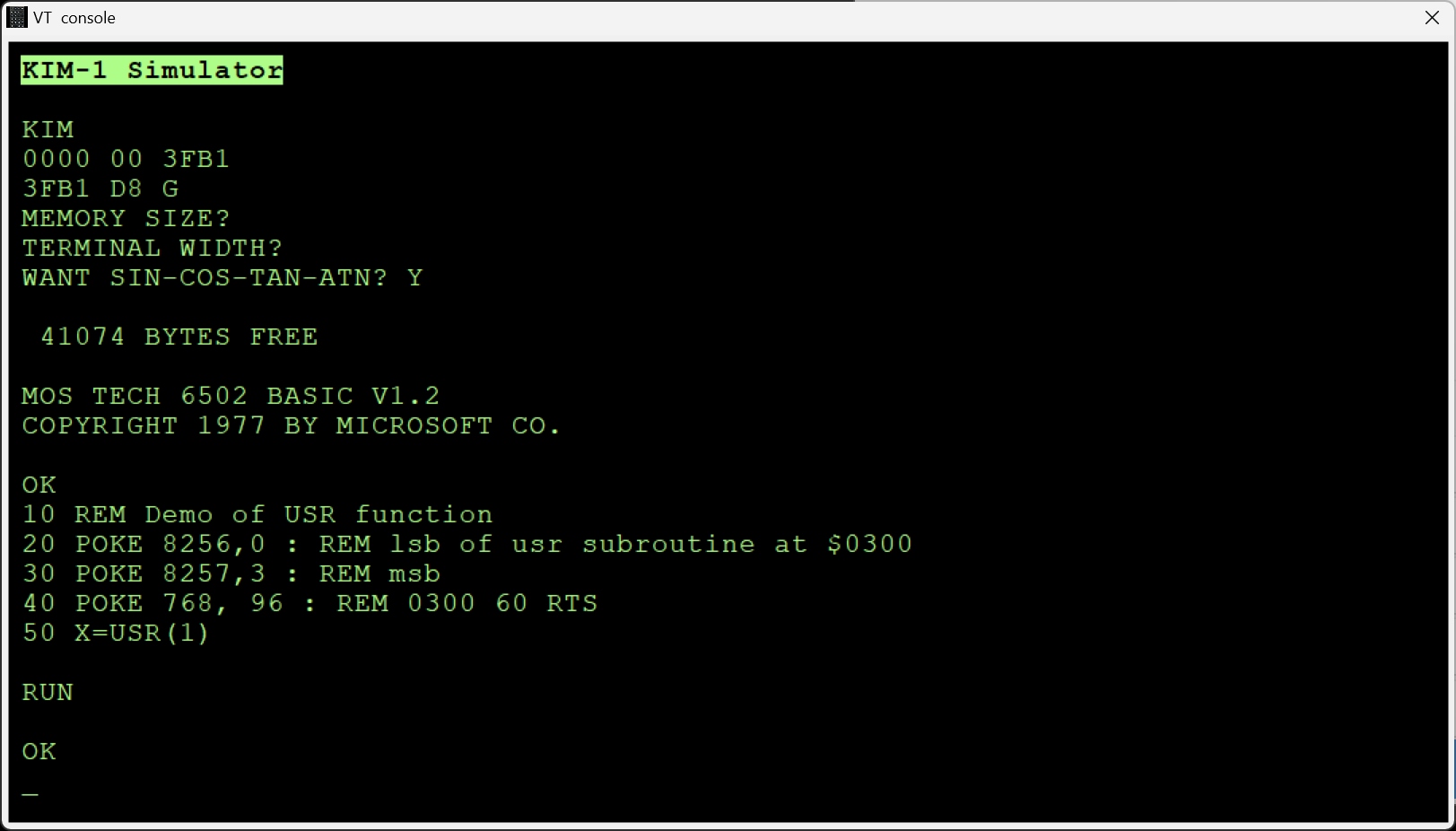
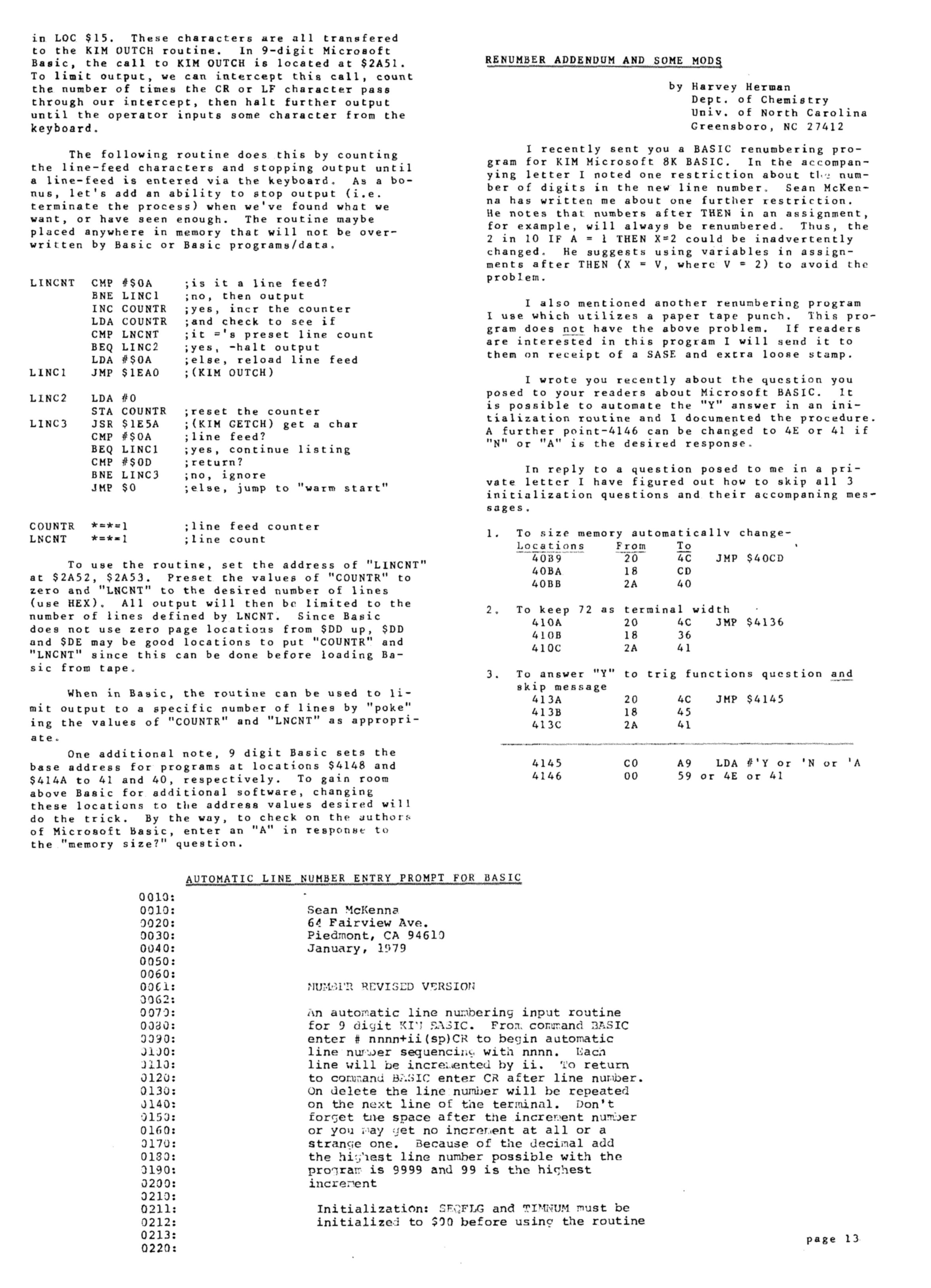
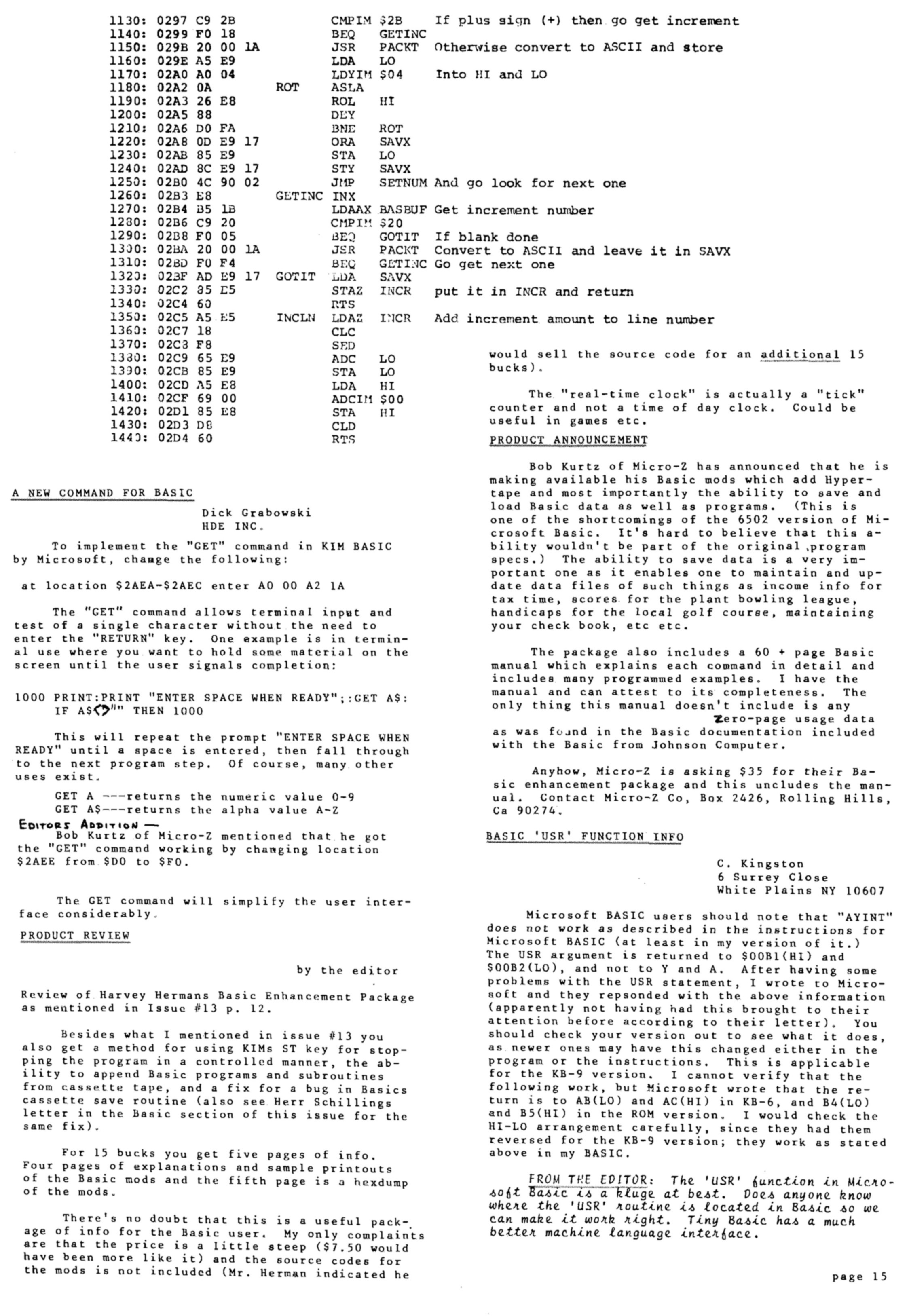
– Vol 14, Tips, Paging, Automatic Line numbers, the GET statement, USR function
Page 1, Page 2, Page 3, Page 4
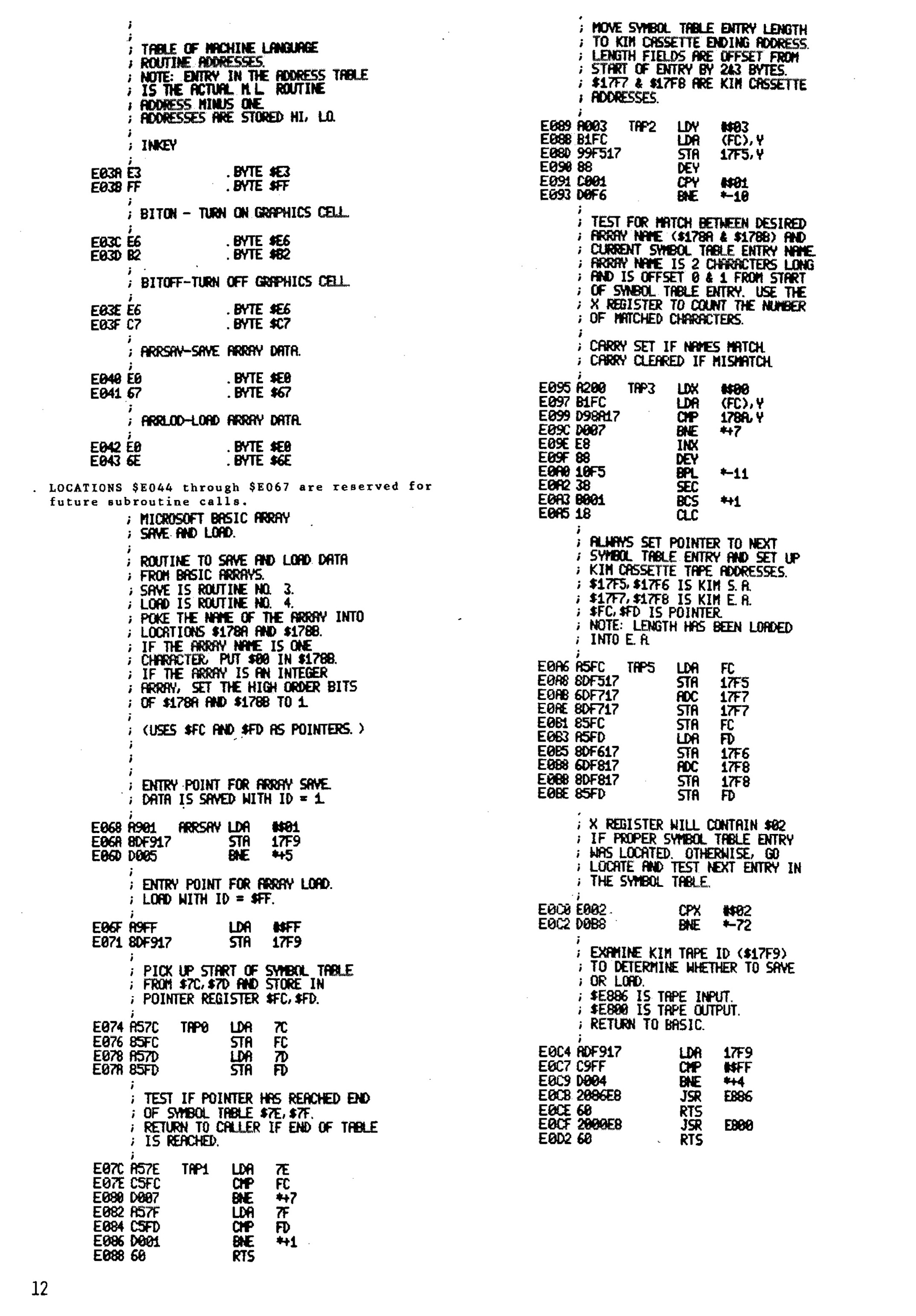
– Vol 15 USR Dispatch, Load/save Basic arrays Page 1, Page 2, Page 3
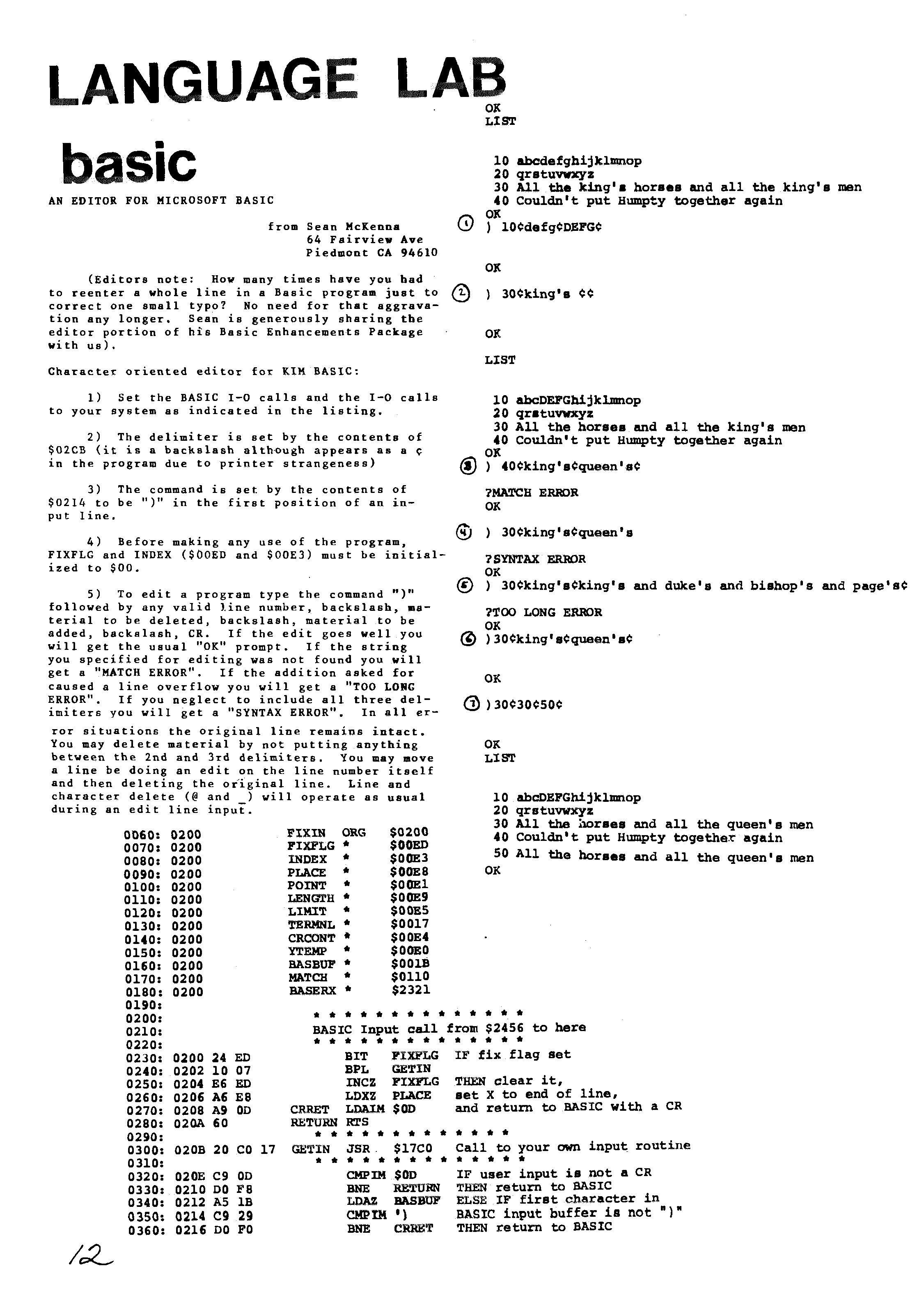
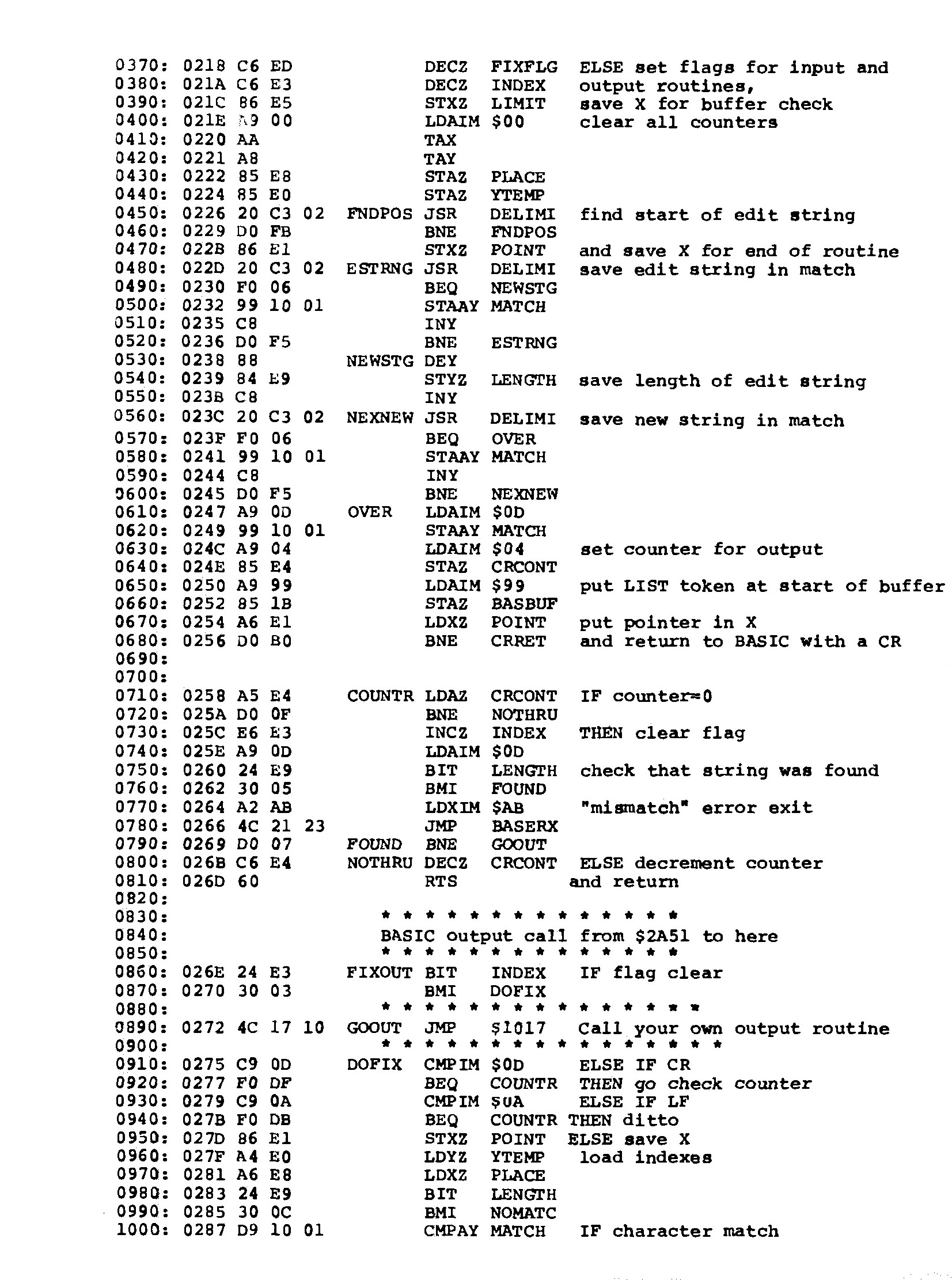
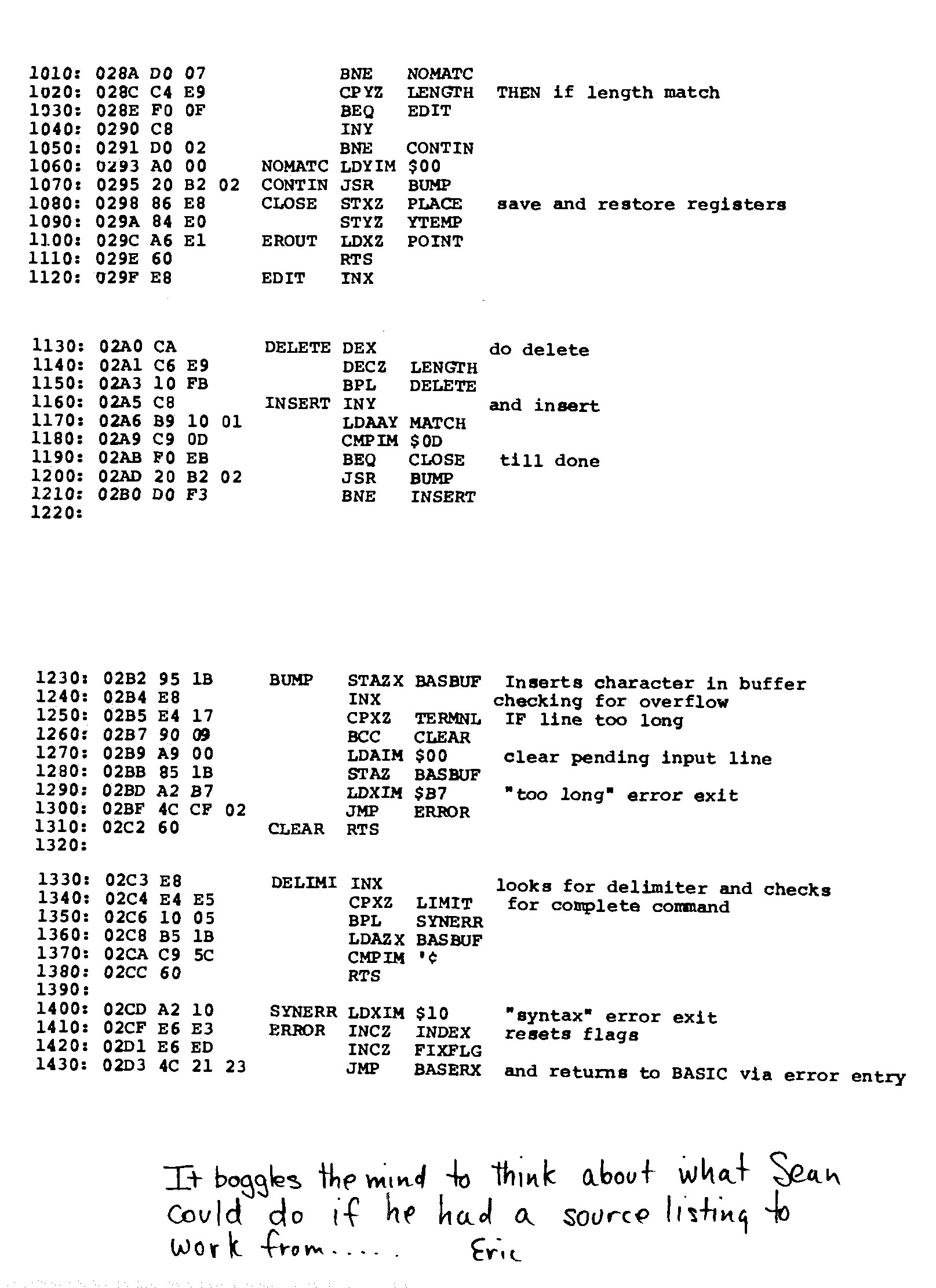
-Vol 16 Line Editor Page 1, Page 2, Page 3, Page 4
-Vol 17 IEEE, Save Load cassette Page 1, Page 2, Page 3, Page 4
Basic V3.0
After I bought MOS Basic for the KIM-1 in 1978 a lot of study went into understanding and adapting the interpreter. In the Dutch club magazine the KIM Kenner (see above) I and others published my work on it, like tape I/O in hypertape format, calculated goto’s, trace mode, paged output and such.
I modified it later on to suit a bit better to my system, that moved from the KIM-1 I/O to keyboard input via a ASCII keyboard, output to video terminal and a parallel matrix printer Heathkit H14. Even later a real serial interface (ACIA 6850) was used for I/O. I also replaced the startup routine, from destructive to reusable and no questions asked.
Here the Micro Ade source of the patches to V3.0 (Parallel keyboard, video output, H14 printer) and nothing asked non-destructive startup routine. I should rewrite that to the current KB-9 V2 to also include the GET and Backspace patches. V1.3 perhaps?
Sources of KB-9 Microsoft Basic v1.1
Adapt KB-9, first step make it faster and smaller
In the previous section the pagetable article was shown, with resources to recreate from source many 6502 Basic’s, like KB-9.
Here an example how I, quick and dirty, used this to create a KB-9 named V1.2 which is smaller and faster than the original.
This is how to prepare for it (Windows, can be done also on Linux)
- Download and unpack the archive of pagetable in a folder on your PC.
- Download and unpack the CC65 package, a C compiler, from which only the assembler and linker is used. I used the Windows binaries.
- Copy CA65.EXE, LD65.EXE and longbranch.mac from the CC65 package to the folder where you unpacked the MS Basic source.
Do the adaptations as described below or your own:
- To save you the work I have collected the adaptations described above in this archive for your convenience here.
- Change whatever you like in the source. It is quite a complicated construction, with macros for every variant, so look carefully at the listing file what really is produced.
Start with no adaptations and then go on studying the listing file and testing. The KIM-1 Simulator is a good tool for testing! Load the symbol table file to see what is where.
- Assemble and link with this simple batch file makekb9v2.bat, resulting in an object, a binary, a listing file and a symbol label file.
ca65 -D kb9 msbasic.s -o tmp/kb9v2.o -l tmp/kb9v2.lst
ld65 -C kb9.cfg tmp/kb9v2.o -o tmp/kb9v2.bin -Ln tmp/kb9v2.lbl
Repeat step 4 and 5 until you are satisfied with the adaptations. The article listed above are a good source of inspiration.
First example: use the ROR instruction and suppress nulls sent to the terminal and Clear decimal and fix GET
I changed this:
-
In define_kim.s make a comment of the following two lines:
CONFIG_NULL := 1
;CONFIG_ROR_WORKAROUND := 1             ; patch HO 2021
Assemble and link with the batch file makekb9v2.bat, this will deliver in the folder tmp/
– kb9v2.bin file : load as usual at $2000
– kb9v2.lbl text file
– kb9v2lst textfile
Start KB9 V2 now at location $3F8E, label COLD_START (used to be $4065, so we gained some RAM), see the lbl file.
Here is an archive with all files mentioned above.
And here the new KB-9 V1.2 executable, faster (no ROR instruction emulation) and a bit smaller.
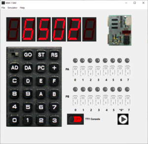
You can test all this with the KIM-1 Simulator (version 0.9.3 lets you load CC65 type of symbol files)
KB-6
I know KB-6 existed. The ‘6’ stands for the precision in digits of the floating point number. In the documentation KB-6 is described.
Never seen a version in the wild. So the reconstruction here is not checked with the original, addresses in the reconstruction from the linker differ from the documentation.
Perhaps the ROR workaround or the insertion of CLD in the init.s caused this.
KB-6 can be ‘reconstructed’ since other versions of 6 digit Microsoft Basic are in the ‘pagetable sources’.
It takes one define added in define_kim.s, changes on the original file are now:
; CONFIG_NULL := 1                      ; patch HO 2021
;CONFIG_ROR_WORKAROUND := 1             ; patch HO 2021
CONFIG_SMALL := 1                       ; patch H0 2021
Assemble and link as above, replace kb9v2 with kb6 in the batch file. See the archive for a working batch file.
COLD_START moves to $3D50, size shrinks to 8K.
Download KB-6 here.
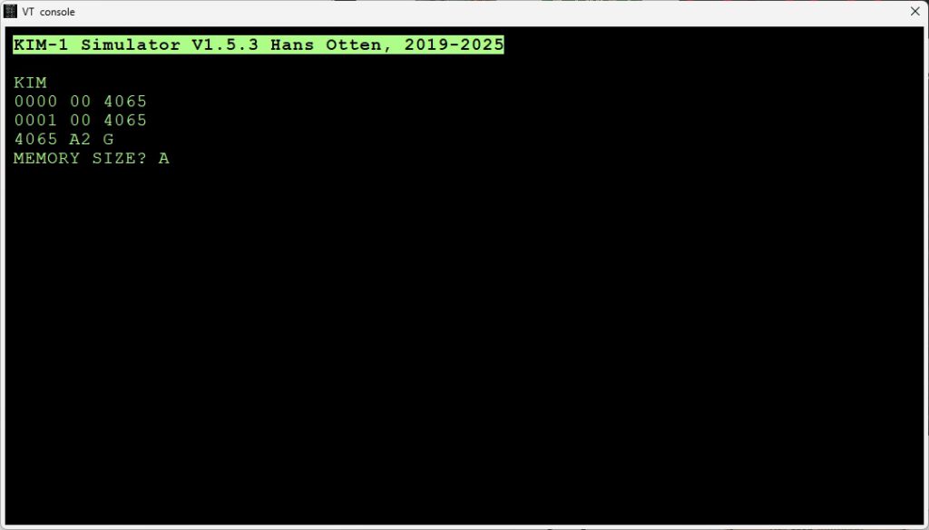
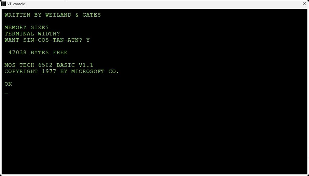
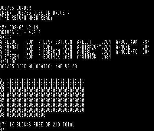
As you can see in the following screenshots it works! Note the number of digits is less, as expected. It should be faster also.
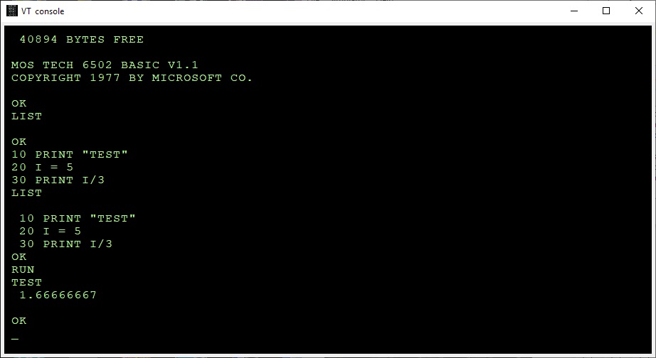
Microsoft Basic for the KIM-1 KB-9
Microsoft Basic for the KIM-1 KB-6, less precision, smaller program size
The GET bug
The bug was described and fixed first by an article in the KIM User note
From the pagetable sources:
BUG: The beq/bne L2AF8 below is supposed to be always taken. For this to happen, the last load must be a 0 for beq and != 0 for bne.
The original Microsoft code had ldx/ldy/bne here, which was only correct for a non-ZP INPUTBUFFER. Commodore fixed it in CBMBASIC V1 by swapping the ldx and the ldy. It was broken on KIM, but okay on APPLE and CBM2, because these used a non-ZP INPUTBUFFER. Microsoft fixed this somewhere after KIM and before MICROTAN, by using beq instead of bne in the ZP case.
  .ifdef CBM1
     ldy  #>(INPUTBUFFER-1)
     ldx  #<(INPUTBUFFER-1)
  .else
     ldx  #<(INPUTBUFFER-1)
     ldy  #>(INPUTBUFFER-1)
..
     beq 08
You can easily fix this in KB9 by changing the branch in $2AEE from $D0 (bne) to $F0 (beq).
I have fixed this in the source of KB9V2 (KB6 does not have the GET statement) .
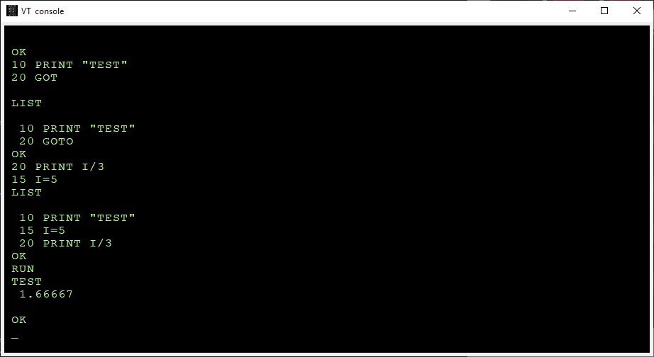
Use the backspace key to correct typing errors
Correcting typing errors can be done with the _ key ($5F). On a video terminal, like we use nowadays it can be done with backspace.
The way characters are handled by the input routine do not allow to just replace the compare with _ (C9 5F) with 08 for backspace.
A trick by Jim W4JBM can be used to reuse the BELL handling (07) to a backspace.
Replace in inline.s
INLINAIM:
    .endif
    .ifndef CONFIG_NO_LINE_EDITING
        cmp     #$07
        beq     L2443
with
INLINAIM:
    .ifndef CONFIG_NO_LINE_EDITING
        cmp     #$08
        beq     L2420

In the original KB9.BIN you can do that with
poke 9260,8
poke 9262,241
The EASTER EGG

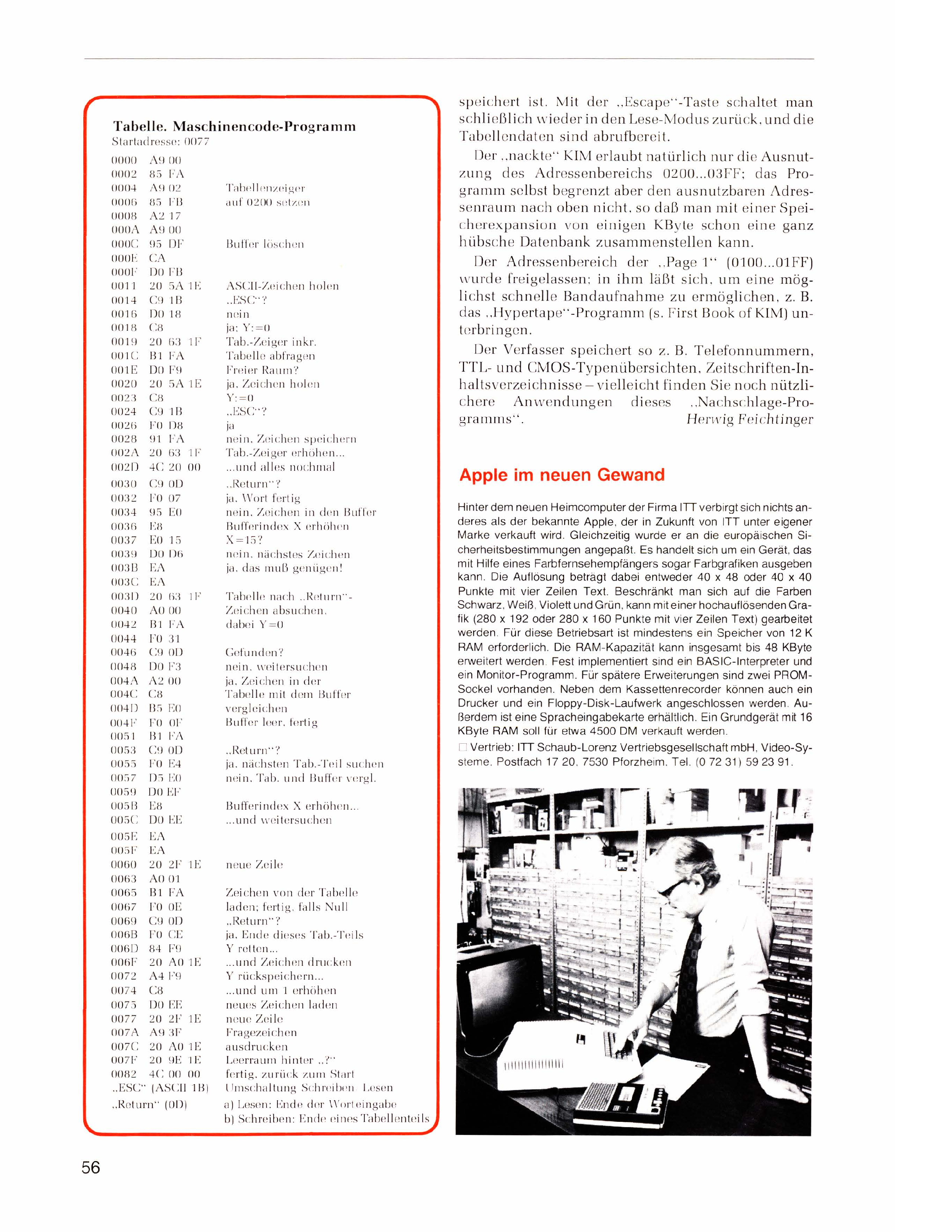
 Hobbycomputer 2
 with his permission
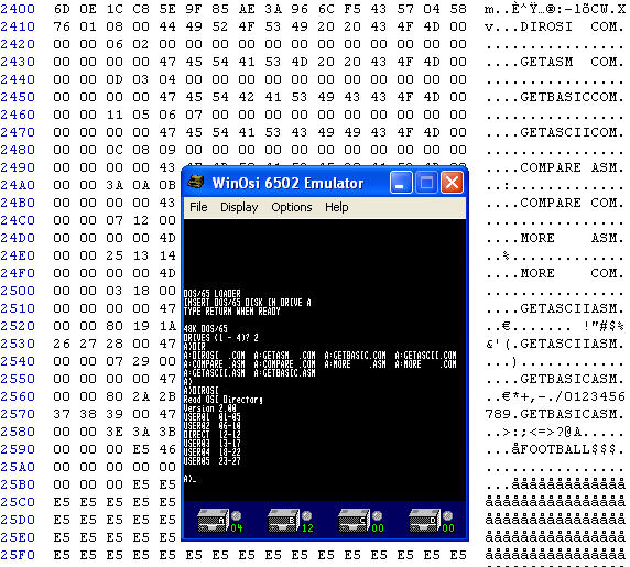
