6530-002 ROM at $1C00 dump of ROM
$1C00-$1FFF KIM-1 listing in KIM-1 Users manual
6530-003 ROM at $1800 dump of ROM
$1800-$1BFF KIM-1 listing in KIM-1 Users manual
On the 6530-002 and -003 PB6 is CS1. PB5 is a normal I/O pin.
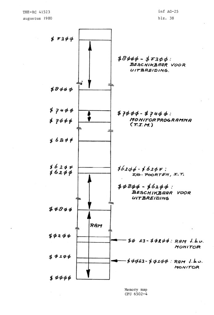
6530-004 ROM at $7000 dump of ROM
$7000-$73FF TIM Terminal Monitor, see the TIM page
On the TIM 65330-004 PB6 is CS1 and PB5 is CS2.
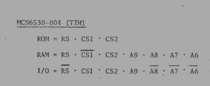
MCS6530-004 Chip Select Equations (thanks Scott Barnes)
6530-005 or R3005-12, no ROM dump
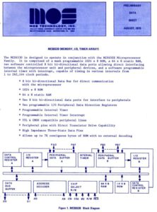
According to this OSI appnote this is an unprogrammed version of the 6530 TIM.
The text in the appnote says:
The 6530-005 is an unprogrammed version of the TIM-1. It has 16 parallel lines as the 6820 but also has a 64 word RAM and a programmable interval timer which can generate an IRQ. The 6530-005 is available from MOS Technology at a cost slightly higher then that of a 6820 PIA.
I have several real 6530-005 IC’s in my stock
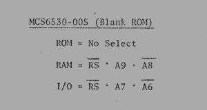
MCS6530-005 Chip Select Equations (thanks Scott Barnes)
6530-006 ROM at $1800 Allied Leisure pinball version 1 (IC6)
6530-007 ROM at 1C00 Allied Leisure pinball version 1 (IC3)
6530-008 ROM at $1400 Allied Leisure pinball version 1 (IC5)
Version 2/3 of Allied Leisure Pinball
6530-009 or R0008-11 IC5 ROM at $1400 dump of ROM
6530-010 or R0006-11 IC6 ROM at $1800 dump of ROM
6530-011 or R0007-11 IC3 ROM at $1C00 dump of ROM
6530P R3004-11 ROM dump, probably also a pinball machine part.
R3014-3 System 1 Sound board
6530-012 Gottlieb System 1 sound board (R3014-12)
6530-013 Gottlieb System 1 sound board (R3014-13)
6530-014 Gottlieb System 80 series sound board (R3016-11)
6530-016 Used in Gottlieb system 80/80A/80B sound boards
6530-024 ROM at $8C00 dump of ROM
Commodore Chessmate (based upon Peter Jenning’s MicroChess)
6530-0210 dump of ROM
6530-241 MIOT in pinball machines
6530-243 MIOT in pinball machines
Commodore diskdrives ROM at $FC00-$FFFF
901466-01 6530-??? 2040 DOS 1.0 Shugart SA390 2040, 3040 and 4040
901466-02 6530-028 4040 DOS 1.2 Shugart SA390 2040, 3040 and 4040
901466-04 6530-034 8050 DOS 2.0 DOS 2.1 Shugart SA390
901483-02 6530-036 8050 DOS 2.5
901483-03 6530-038 8050 DOS 2.5 Micropolis 1006-II (8050)
901483-04 6530-039 8050 DOS 2.5 Tandon TM100-3M (8050)
901884-01 6530-040 8X50 DOS 2.7 Tandon TM100-3M (8050) Tandon TM100-4M (8250)
901885-01 6530-044 8X50 DOS 2.7 Micropolis ???
901885-04 6530-047 8X50 DOS 2.7 Micropolis 1006-II (8050) Micropolis 1006-IV (8250) Micropolis 1106-II (Safari, 8050) Micropolis 1106-IV (Safari, 8250)
901869-01 6530-048 DOS 2.7 M.P.I. 101SM (8050)M.P.I. 102?? (8250)
251256-02 6530-050 8250 DOS 2.7 Matsushita JU-570-2 (8250LP)
Most of the information on this pages is also found on the pages of Martin Hoffman Vetter


 \
\