XKIM is developed by Bob Applegate to support his SD-Shield.
By adding SD-Shield support to the KIM-1 Simulator by Eduardo Casino we can run XKIM there now!
KIM
0200 00
0201 48
E000
E000 4C G

Extended KIM Monitor v1.8 by Corsham Technologies, LLC
www.corshamtech.com

>?
Available commands:

  ? ........... Show this help
  C ........... Show clock
  D ........... Disk directory
  E xxxx ...... Edit memory
  H xxxx xxxx . Hex dump memory
  J xxxx ...... Jump to address
  K ........... Go to KIM monitor
  L ........... Load HEX file
  M xxxx xxxx . Memory test
  O xxxx xxxx . Calculate branch offset
  P ........... Ping disk controller
  S xxxx xxxx . Save memory to file
  T ........... Type disk file
  K ........... Go to KIM monitor
  ! ........... Do a cold start


>C
Date: 03/25/2026, 15:16:47

>Disk Directory...
   bootsdshield-kimrom.bin
   bootsdshield.bin
   bootsdshield.pap
   CPM-BOOT.DSK
   kb9.ihex
   KIM-1 simulator start.jpg
   kim-1-sdshield.zip
   kimsimSETTINGS.jpg
   M2000.BIN
   newimage.dsk
   SD.cfg
   SDMP1.jpg
   SDMP2.jpg
   SDMP3.jpg
   SDMP4.jpg
   SDMP5.jpg

>T - Enter filename: SD.CFG
# SD Card Disk Configuration
# Format: drive:filename or driveR:filename (for read-only)
0:CPM-BOOT.DSK
1:newimage.dsk

>S 2000-2199
Enter filename, or Enter to display to console: K2000.BIN
..........................
>Disk Directory...
   bootsdshield-kimrom.bin
   bootsdshield.bin
   bootsdshield.pap
   CPM-BOOT.DSK
   K2000.BIN
   kb9.ihex
   KIM-1 simulator start.jpg
   kim-1-sdshield.zip
   kimsimSETTINGS.jpg
   M2000.BIN
   newimage.dsk
   SD.cfg
   SDMP1.jpg
   SDMP2.jpg
   SDMP3.jpg
   SDMP4.jpg
   SDMP5.jpg

>T - Enter filename: M2000.BIN
:102000001510922D4C000020902860A00CA900997A
:10201000922D8810FA4CD425A9FF8D942DA9008DFE
:102020009E2D60084898488A48AD942D3004A00041
:10203000911A68AA68A8682860A51A49FF2D952DED
:102040008D952DA51B49FF2D962D8D962D18602061
:10205000CD20A90F204325B02BA00CB11A8522A0BA
:102060001FB10E911A8810F920A923A00CB11AC52E
:1020700022F00AA9009002A980A00F911AA522A01F
:102080000C911A186020CD20206428A90F20432528
:102090009037A900A010911AC8C020D0F9A9E5A0D6
:1020A00000911AA901204325B01FA001B11A910E79
:1020B000C8C020D0F7ADB12DA000910E20AF26A949
:1020C0000120D22720A9231860A9FF3860A00EA9FB
:1020D00000911AA000B11A8D942D290FAACA1003DD
:1020E000AEB02DADB12D911A8A4CD42520D320202D
:1020F000A625206428A00EB11A10021860A90F208E
:01210000439B
:00000001FF
>
>L
Enter filename, or Enter to load from console: m2000.bin
.................
Success!
See also:
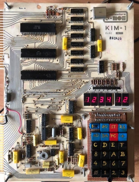
KIM-1 connectors: beware the Chinese cheap variants!
The KIM-1 needs 2 edge connectors.
The specifications are: card edge; PIN: 44; 3.96mm
When you search for those, ...
Magazines: Compute! and Compute II
The pages om Magazines had an update.
MICRO has its own page with all Best of MICRO pfds.
Compute! and Compute II ar...
All documents in the MTU pages are now clean and higher quality, about 50 new PDFs.
I got hold a about 10 cm of MTU documents. Several I already had in PDF format, some not available yet.
I took the oppo...
Focal-65 V3D for TIM and KIM-1
Focal on the 6502, a page on this small language, originating for Digital Equipment.
A small interpreter (about 5K) for...
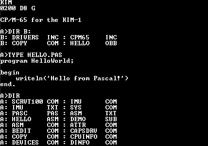
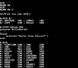 Thanks to the work of David Given (who developed CP/M-65) and Eduardo Casino (who ported CP/M-65 to the KIM-1 with the SD-Shield (developed by Bob Applegate of Corsham Technology) and the addition of the SD-Shield simulation to the KIM-1 Simulator by Eduardo Casino I can run my Pascal-M compiler (written by Mark Rustad in 1977 and ported my Hans Otten to Lazarus and ported by david Given to CP/M-65)) on my PC in the KIM-1 Simulator (developed by me Hans Otten since 2019) compiling itself and showing it can compile ‘hello world’ program.