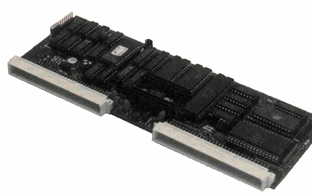
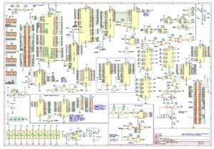
The 680x/650x Test system allows to test, with the CPU itself performing the test, the MC680X and MCS650X families.
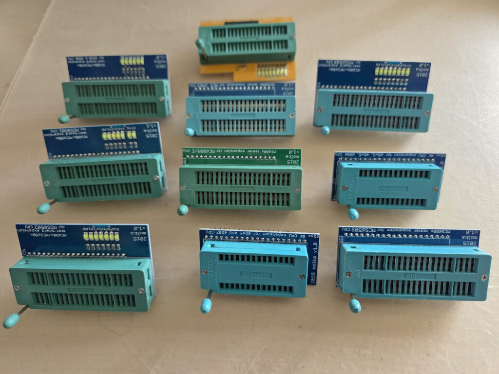
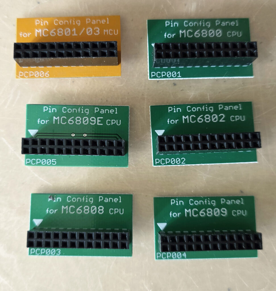
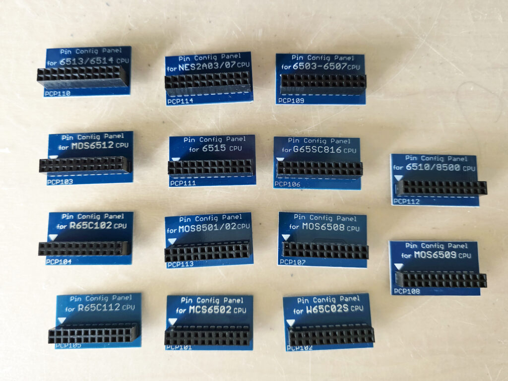
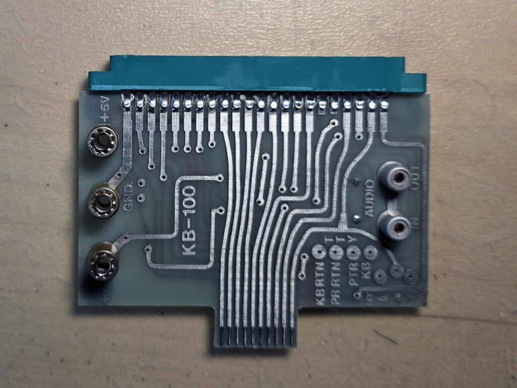
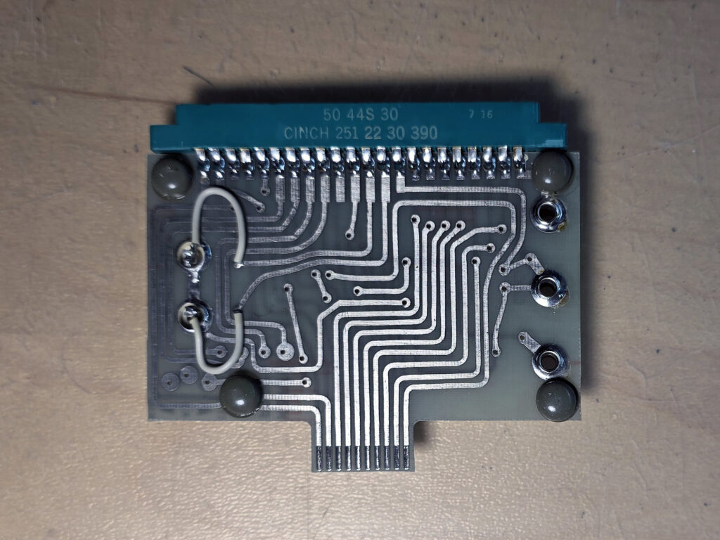
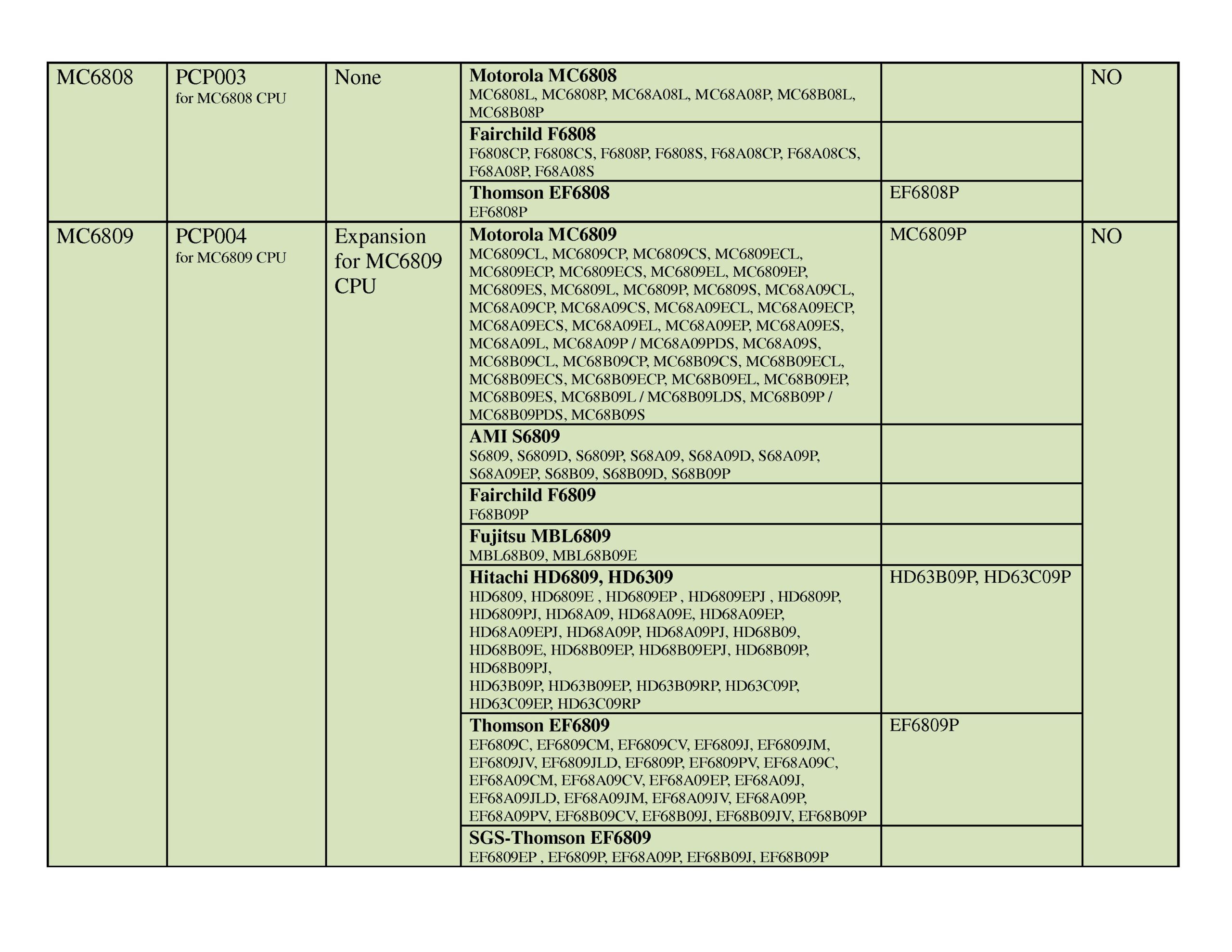
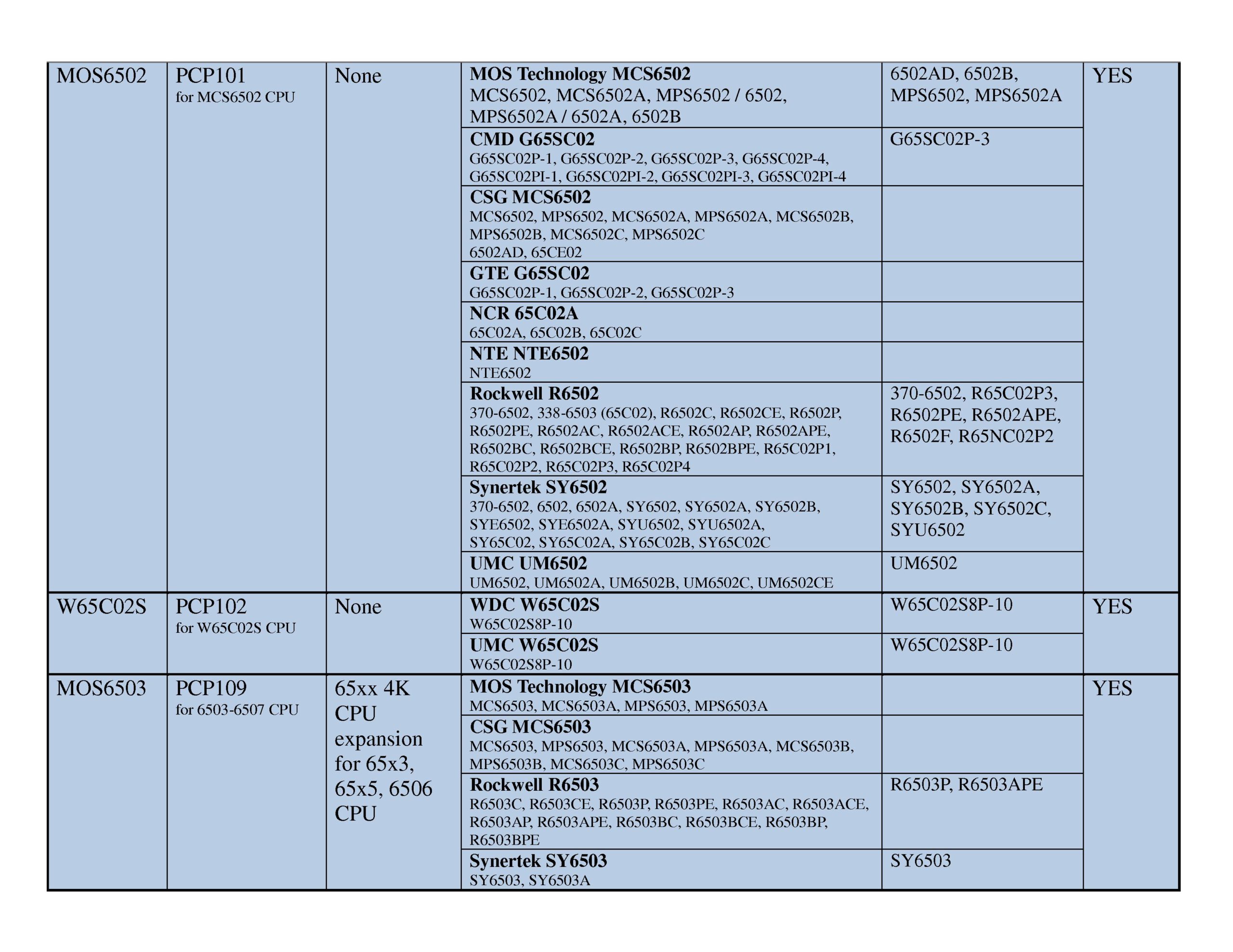
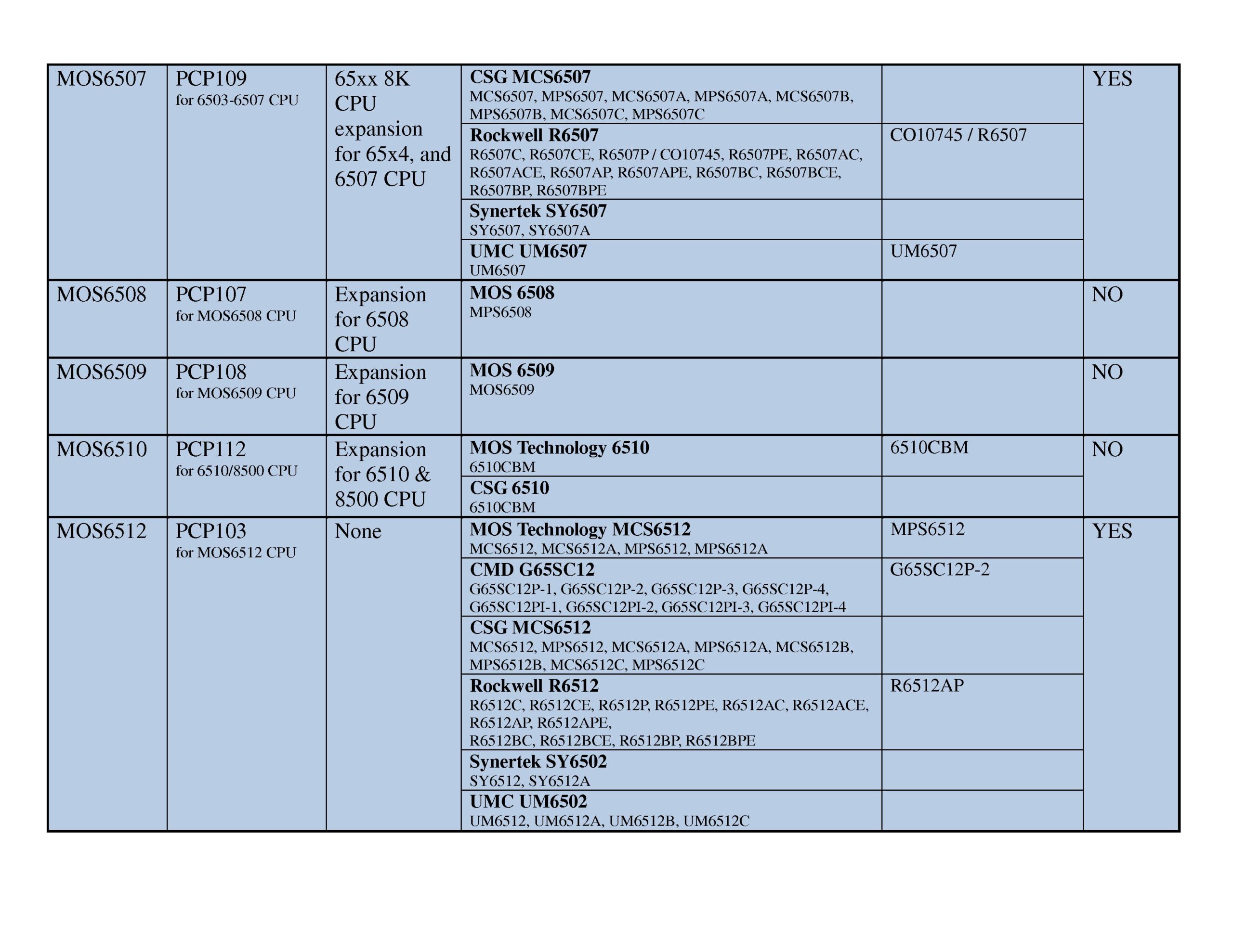
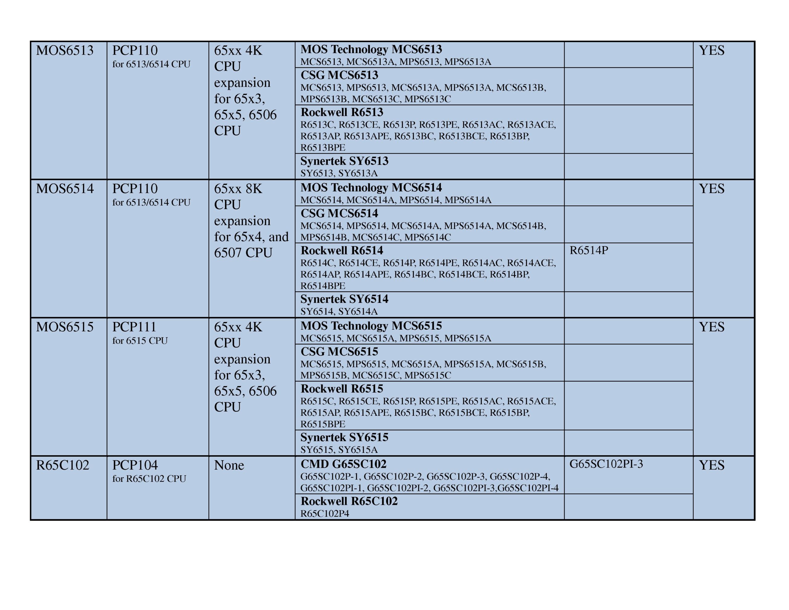
The 680x/650x board uses expansion boards, as well as a new feature called the PCP (Pin Configuration Panel). The PCP handles differences in pin-puts for the various chips to be tested and configures the base system to know which chip is being used. The expansions boards handle anything else, as well as providing LEDs for additional testing of some chips.
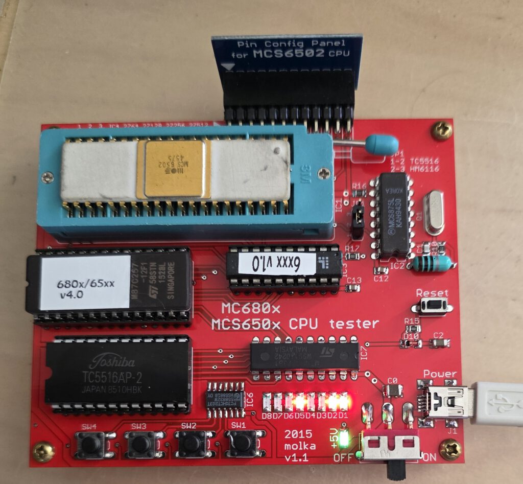
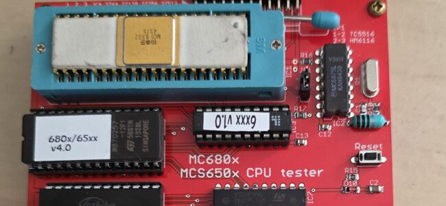
The photo above shows the tester examining this very old 6502, from week 45 1975. The extended test shows this CPU is missing the ROR instruction, added to the 6502 in 1976.
And it also shows it is a NMOS IC.
The quality of the board, the flexibility and wide support for so many MC680X and MCS6502 family CPU’s makes this my favorite tester among the 6502 testers.
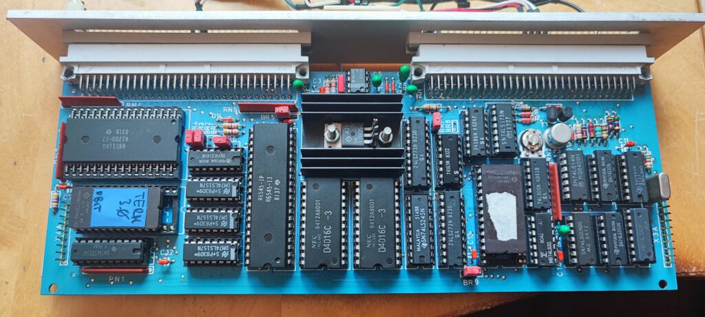
The board consists of the base components of a MC680x/MCS650x system:
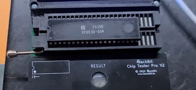
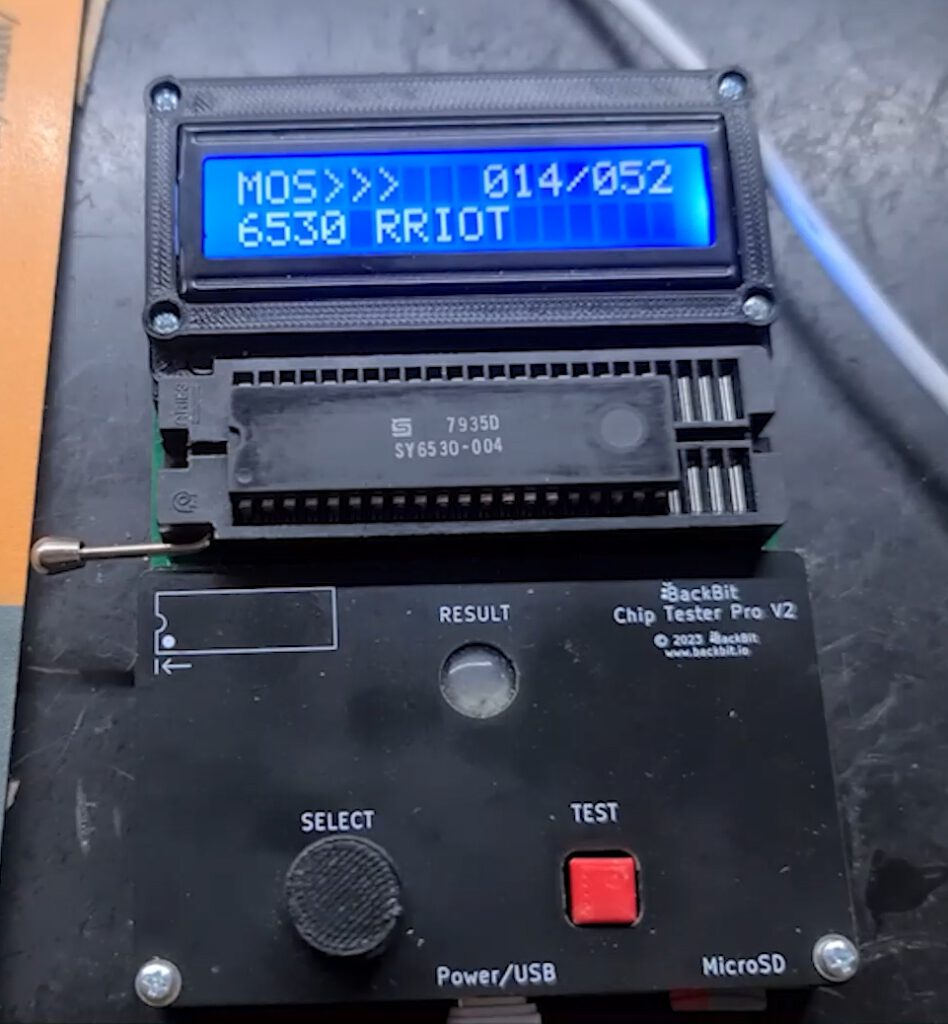
• 40-pin ZIF socket – for the tested CPU – provides easy replacement of the CPUs.
• Clock generator with 4MHz crystal oscillator for generating 1, 2 or 4MHz system clock of the CPU (not user selectable alas)
• 2K x 8bit (HM6116/TC5516) static RAM for variable and stack area.
• 8K x 8bit (D2764) EPROM holds the test programs. This program supports 4 push buttons as inputs, and 8 LEDs, as output devices. It also provides basic and special feature test routines.
• 24-pin header provides facility to configure the different function pins of different CPU/MCU types.
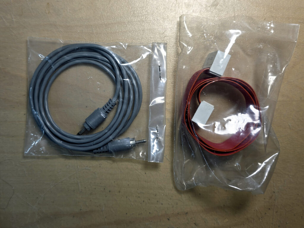
The board requires a single +5V power supply (200mA) provided through a mini-USB connector.
There is a power switch and power indicator LED in the lower right corner of the test board.
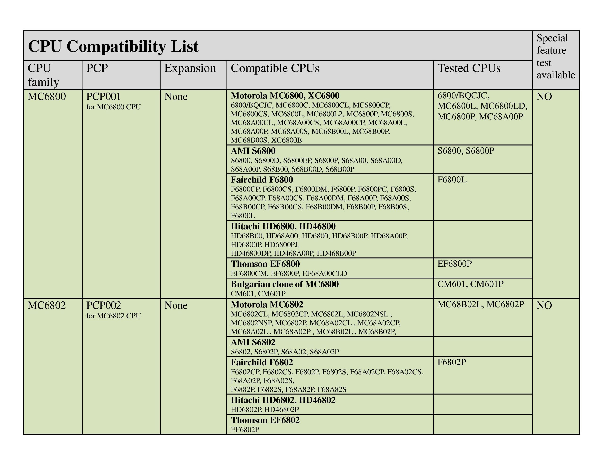
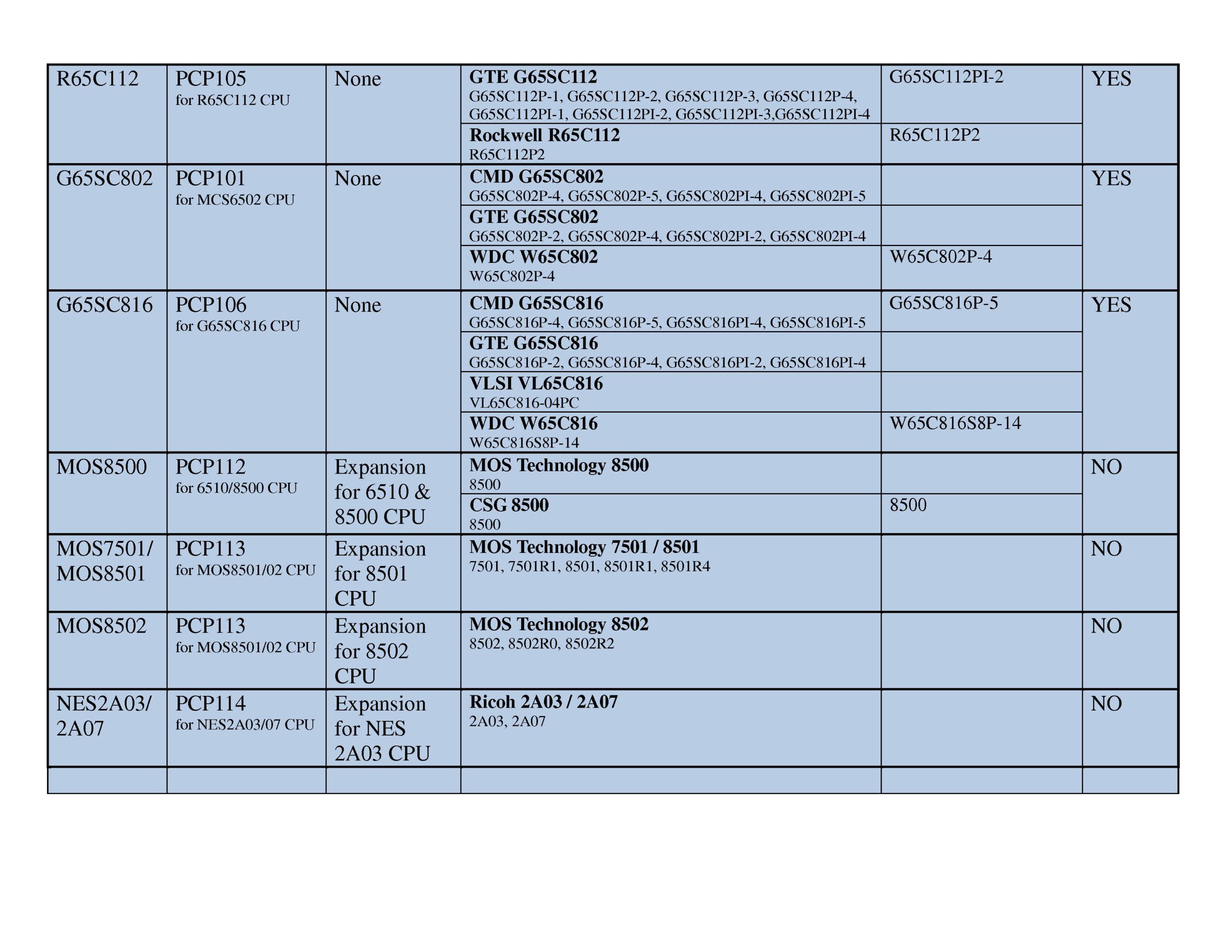
You can buy a basic system, which allows to test the more common CPU’s:
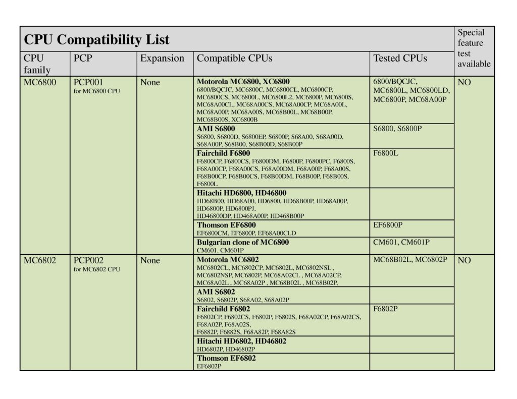
6800 Family (NMOS, any speed/manufacture)
6800
6802
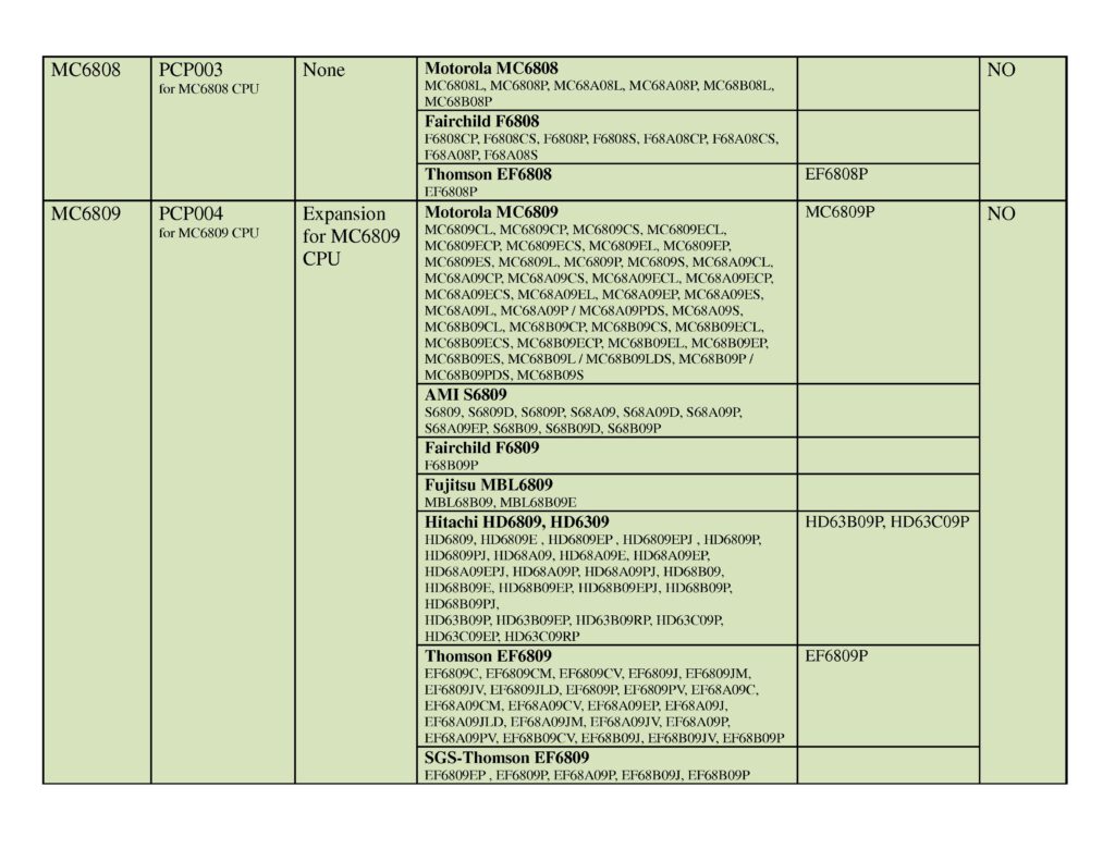
6808
6502 Family (any manufacture/speed)
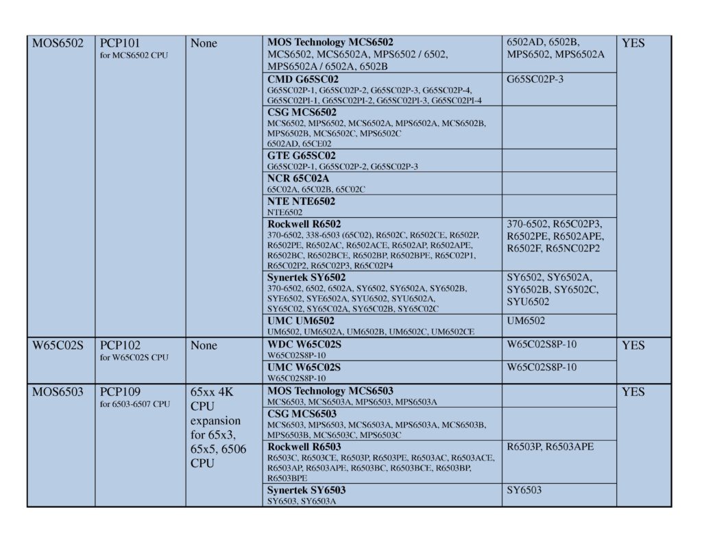
6502/65C02 NMOS/CMOS
65C02S
6512/65SC12
65C102/65SC102
65C112/65SC112
65SC802
65C816/65SC816
The full and more expensive system comes with many more expansions and PCPs.
It allows to test:
6800 Family (NMOS, any speed/manufacture)
6800
6801
6803
6802
6808
6809/E
6502 Family (any manufacture/speed)
6502/65C02 NMOS/CMOS
65C02
6503/04/05/06/07/08/09
WD65C02S
6510 (as used in Commodores)
6512/65SC12
6513/14/15
65C102/65SC102
65C112/65SC112
65SC802
65C816/65SC816
8500/8501/7501 (as used by Commodore)
Ricoh 2A03/2A07 Nintendo CPU

Special feature test (available for 6502 family CPUs)
To activate the special feature test SW1 and SW4 should be pressed together and held for 3 seconds.
The program checks if the ROR bug is present.
Then checks if jump error on page boundaries is present.
Finally checks the technology of the inserted CPU, NMOS or CMOS
And also checks if this is a 16 bit 65816 CPU
D1 – ROR bug detected
D2 – Jump page boundaries bug detected
D3 – not used
D4 – not used
D5 – NMOS CPU detected
D6 – CMOS CPU detected
D7 – 65C802 or 65C816 CPU detected
D8 – not used