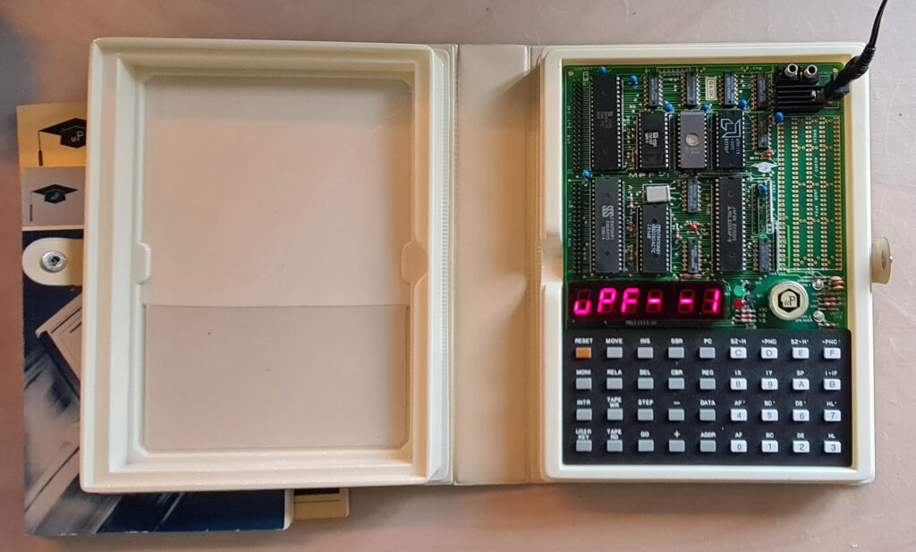
Ruud Baltissen started the whole KIM-1 Replica world by publishing a page many years ago about Building a KIM-1
All replica’s, from the MICROKIM to the Nachbau followed his design.
Replicated here the are relevant text and schematics by Ruud.
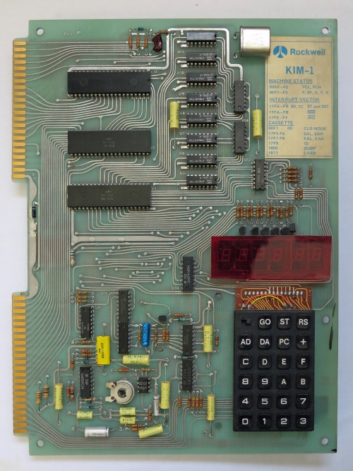
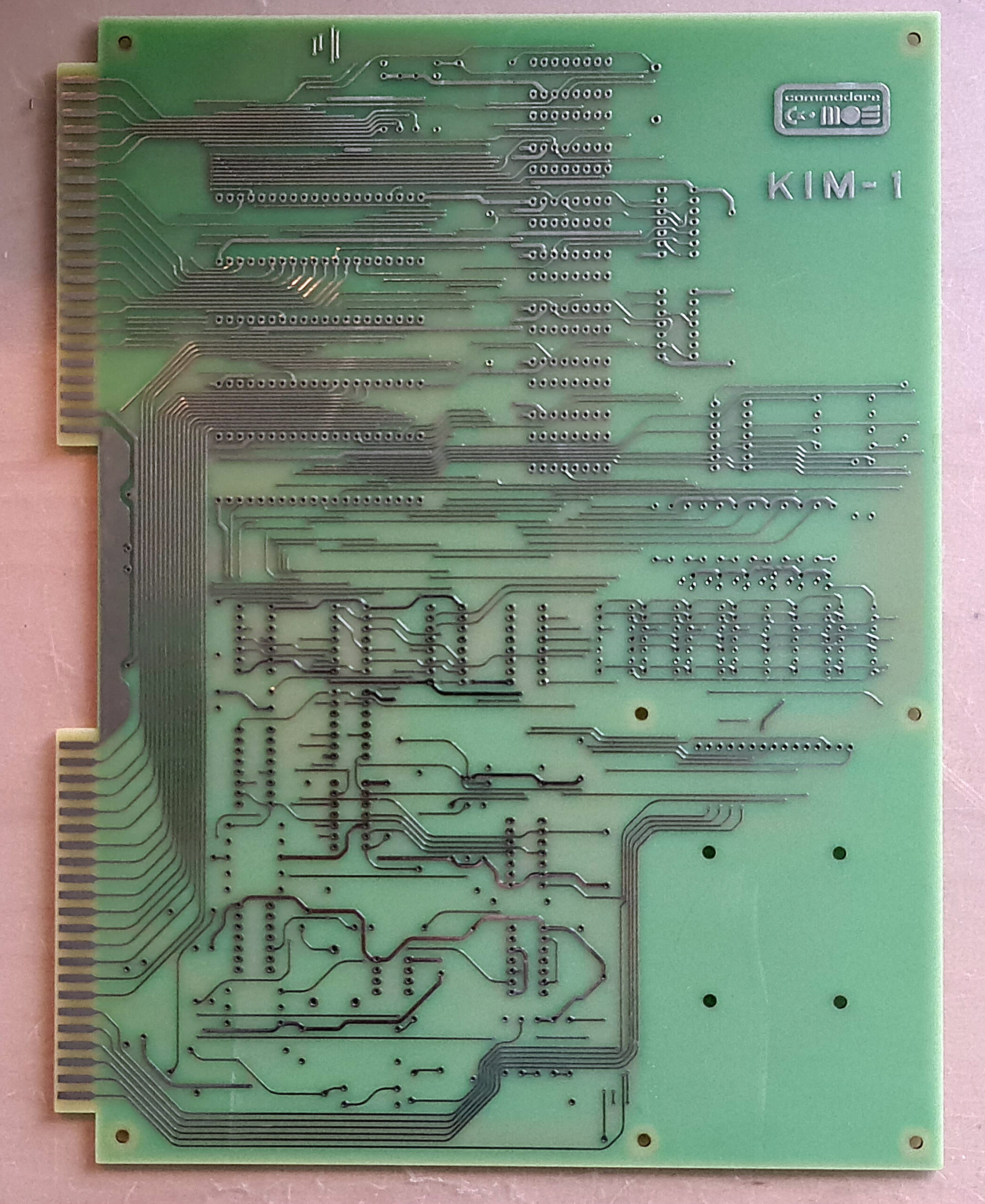
Build a KIM-1
The goal of this project is to rebuild the KIM-1. This isn’t “Just take the schematic of the KIM and go ahead!”. The KIM-1 uses two 6530s that are custom ICs and therefore cannot be bought in any shop. This project uses replacement parts.
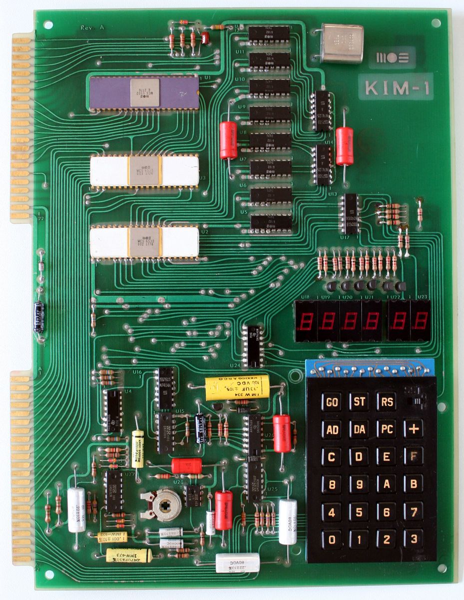
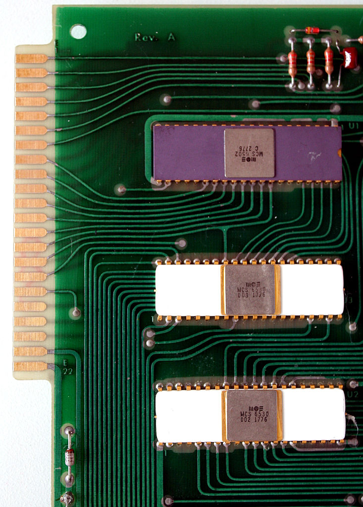
The troubleshooter: 6530
As said, the KIM-1 has two 6530s on board. For more info about this IC, please read about the 6530 here. Anybody who is a little bit familiar with the hardware market can tell you that you cannot buy the 6530 as a regular part. And the 6530 is a custom IC: Commodore made various types but all were branded 6530. For example, the 6530 found in the CBM 4040 drive is different from the ones of the KIM. Even the two 6530s of the KIM itself are different: in this case it is the content of the builtin ROM.
Happily enough there is another IC available that can be used as replacement: the 6532.
The 6532 has 16 I/O lines, an internal timer and 128 bytes of RAM onboard, but no ROM. For this project we’ll use an external EPROM as replacement. The pin out of the 6532 is completely different but that should not be a problem.
Another difference is that a 6532 has pin PB6 available where a 6530 hasn’t. See it as a bonus as I haven’t found any reason how it could jeopardize our project.
The 6530 can generate a IRQ but in case of the KIM-1 this feature isn’t used. The main reason is that pin PA7 is needed to output the signal and it is used for other things. The 6532 has a separate IRQ output. I used two jumpers, J54 and J5, to enable someone to use this function if needed.
The last and major difference however lays in the way the registers are selected:
function:       RS:  A6:  A5:  A4:  A3:  A2:  A1:  A0:  R/W:

RAM              0    x    x    x    x    x    x    x    x

DRA              1    x    x    x    x    0    0    0    x     A
DDRA             1    x    x    x    x    0    0    1    x     B
DRB              1    x    x    x    x    0    1    0    x     C
DDRB             1    x    x    x    x    0    1    1    x     D

PA7, IRQ off,
      neg edge   1    x    x    0    x    1    0    0    0     F
PA7, IRQ off,
      pos edge   1    x    x    0    x    1    0    1    0     G
PA7, IRQ on,
      neg edge   1    x    x    0    x    1    1    0    0     H
PA7, IRQ on,
      pos edge   1    x    x    0    x    1    1    1    0     I

read interrupt
       flag      1    x    x    x    x    1    x    1    1     E

read timer,
       IRQ off   1    x    x    x    0    1    x    0    1     J
read timer,
       IRQ on    1    x    x    x    1    1    x    0    1     K

Clock / 1,
       IRQ off   1    x    x    1    0    1    0    0    0     L
Clock / 8,
       IRQ off   1    x    x    1    0    1    0    1    0     M
Clock / 64,
       IRQ off   1    x    x    1    0    1    1    0    0     N
Clock / 1024,
       IRQ off   1    x    x    1    0    1    1    1    0     O

Clock / 1,
       IRQ on    1    x    x    1    1    1    0    0    0     P
Clock / 8,
       IRQ on    1    x    x    1    1    1    0    1    0     R
Clock / 64,
       IRQ on    1    x    x    1    1    1    1    0    0     S
Clock / 1024,
       IRQ on    1    x    x    1    1    1    1    1    0     T
In total 5 address lines are used, meaning 32 registers. But 11 of the 19 registers have one or more mirrors.
Read:          J E J E         K E K E         J E J E         K E K E
Write:         F G H I         F G H I         L M N O         P R S T
R/W:           A B C D         A B C D         A B C D         A B C D
As we can see, the last 16 registers equal the 16 of the 6530 itself. So now we have to develop some logic which will do the following:
- The I/O of the 6532 is only visible within a range of 64 bytes
- The first 16 bytes represent register 16 to 31
- The next 48 bytes are mirrors of the first 16
- Only 64 bytes of RAM are used
Conclusion:
- Input A6 won’t be used and can be tied to GND
- Input A4 is connected to address line A4 of the 6502 via a NAND gate.
- The second input of that NAND gate is connected to the /CS2 input.
The idea behind this is simple: The moment that the I/O part of the 6532 is selected, the NAND gate outputs a (H) thus selecting the wanted last 16 registers. If needed, the user can select the other 16 registers as well by connecting the second input of the NAND gate to +5V.
- A 74LS138 enables the /RS and /CS2 lines at the right moment.
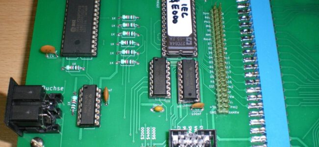
ROM and RAM
Here we have a luxury problem. We only need 2K of (EP)ROM like the 2716. The problem is that the 2716 is hard to find and more expensive then the 2764 or its bigger brothers. When we use a bigger EPROM we could tie the unused address lines to GND.
The same problem occurs with the RAM. In this case I have chosen for a 62256, a 32 KB RAM. This looks like a massive overkill but see later.
If we have to use bigger RAMs or EPROMs anyway, it is quite easy to use other parts of that chip by OR wiring the CS line with more Kx outputs of the main 74145. In case of the EPROM we also can connect switches to the surplus address lines and have the advantage of a multi-KERNAL system.
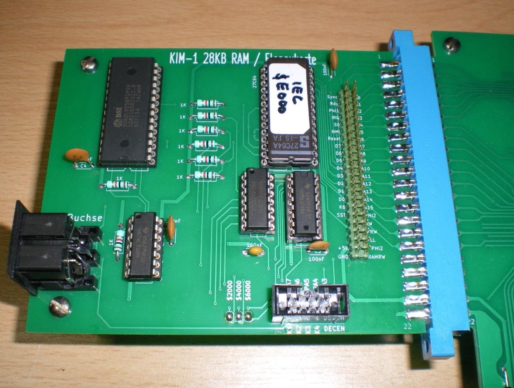
Extra address range
KIM-1 only supported an address range of 8 KB in the first place. The pin DECEN at the Userport can be used to extend that range but HAS to be connected to GND for the original configuration. The idea is that external cards can use this input to alter the range.
I added an extra 74145, IC7, and two jumpers that enable the user to make a more efficient use of the hardware. Both jumpers, J2 and J3, have to be closed to start with.
If you don’t want to use the 74145 at all, only close jumper J1.
The first thing one can do is to let the binary start at address $F800. Your self built KIM will still behave as usual. Now you can add your own RAM from address $0000 on up to $E000 and the only thing you have to do is remove jumper J2.
If you are only interested in adding RAM, a better idea is to use the original one, IC4, the 62256 32 KB RAM. You only have to remove the jumpers J13..17 and to close one or more pair of pins of jumper block J18. By closing all four pair of pins you make use of the full 32 KB.
Jumper J3 is only needed if you want to expand your self built KIM even further and want to use, for example, the $E000/$FFFF range for (EP)ROM.
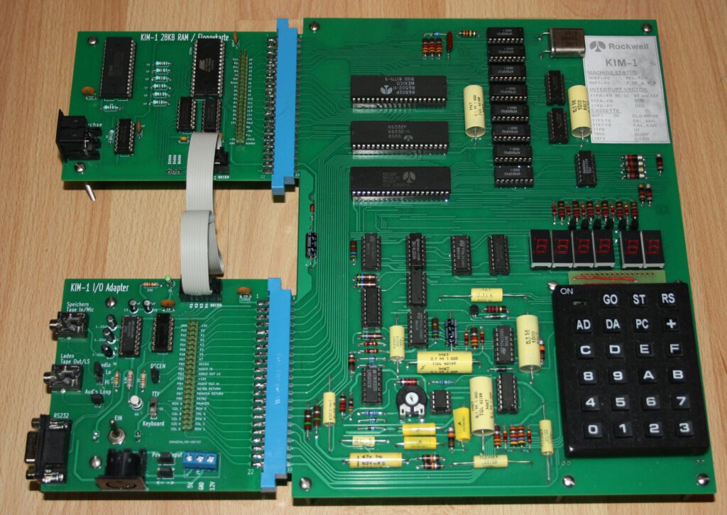
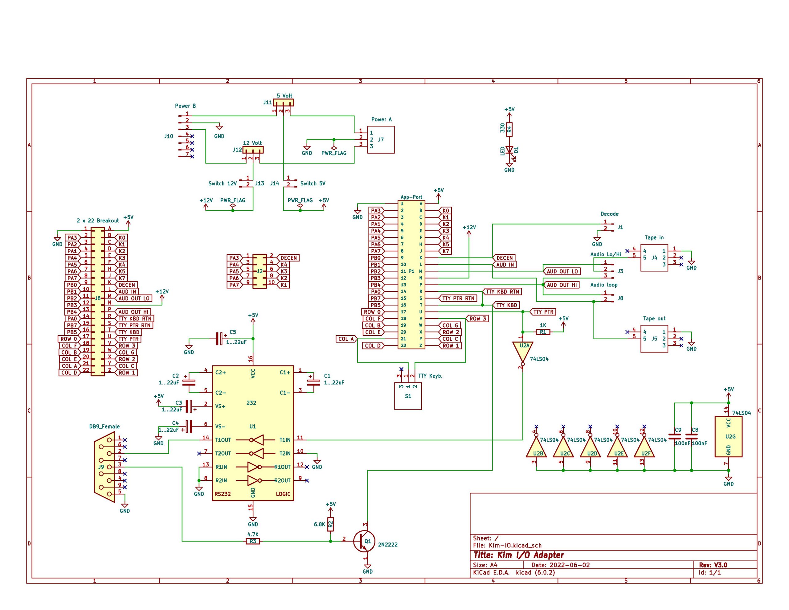
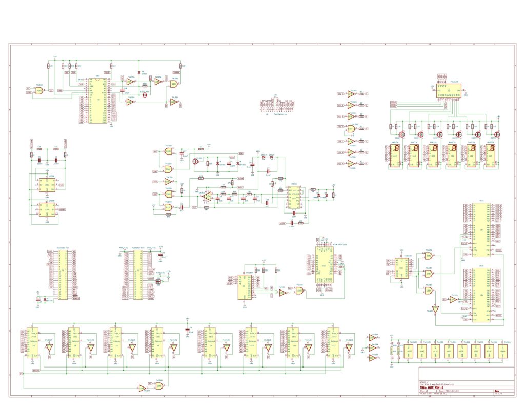
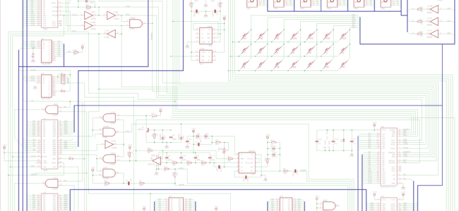
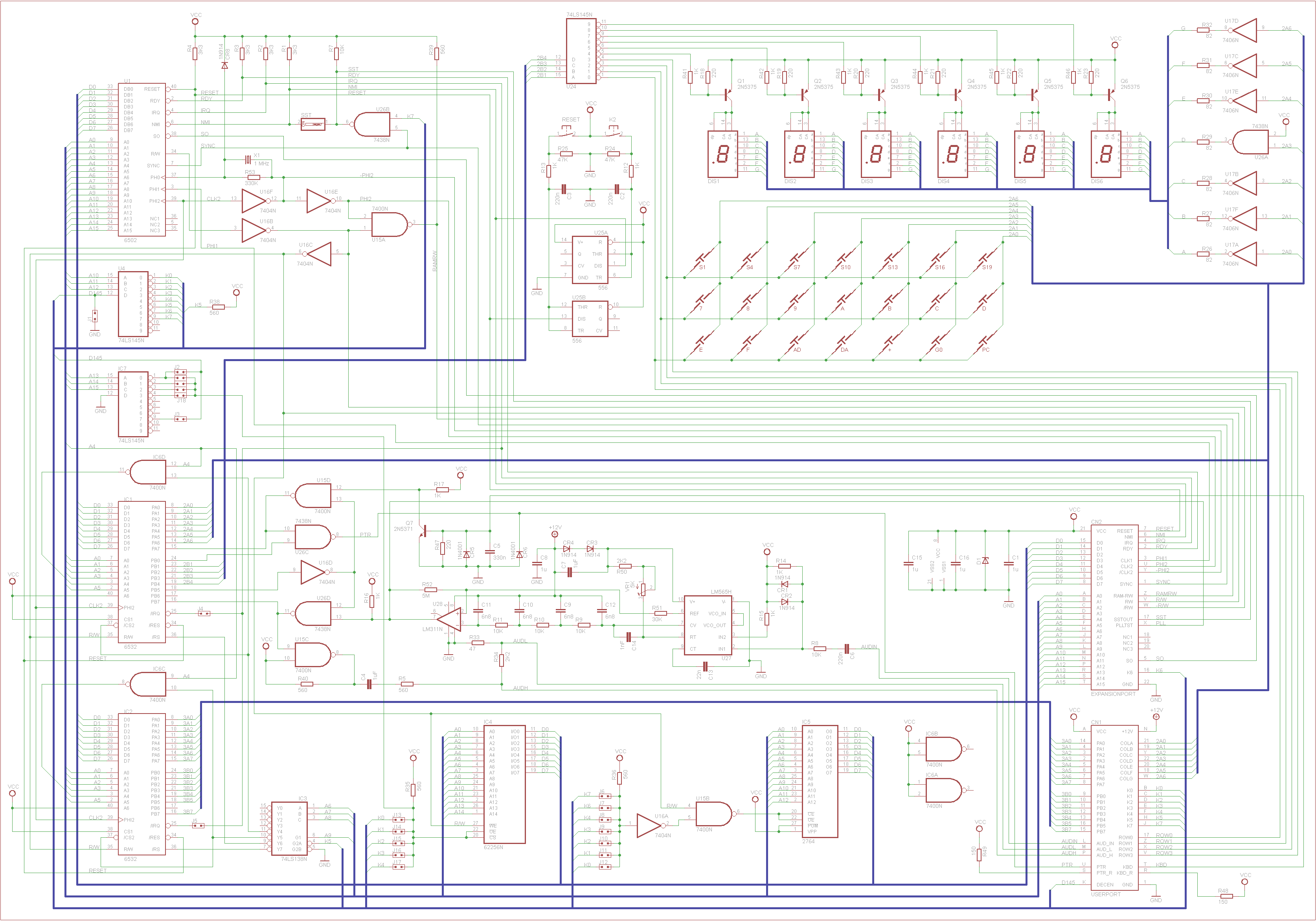
Schematics of the new KIM-1
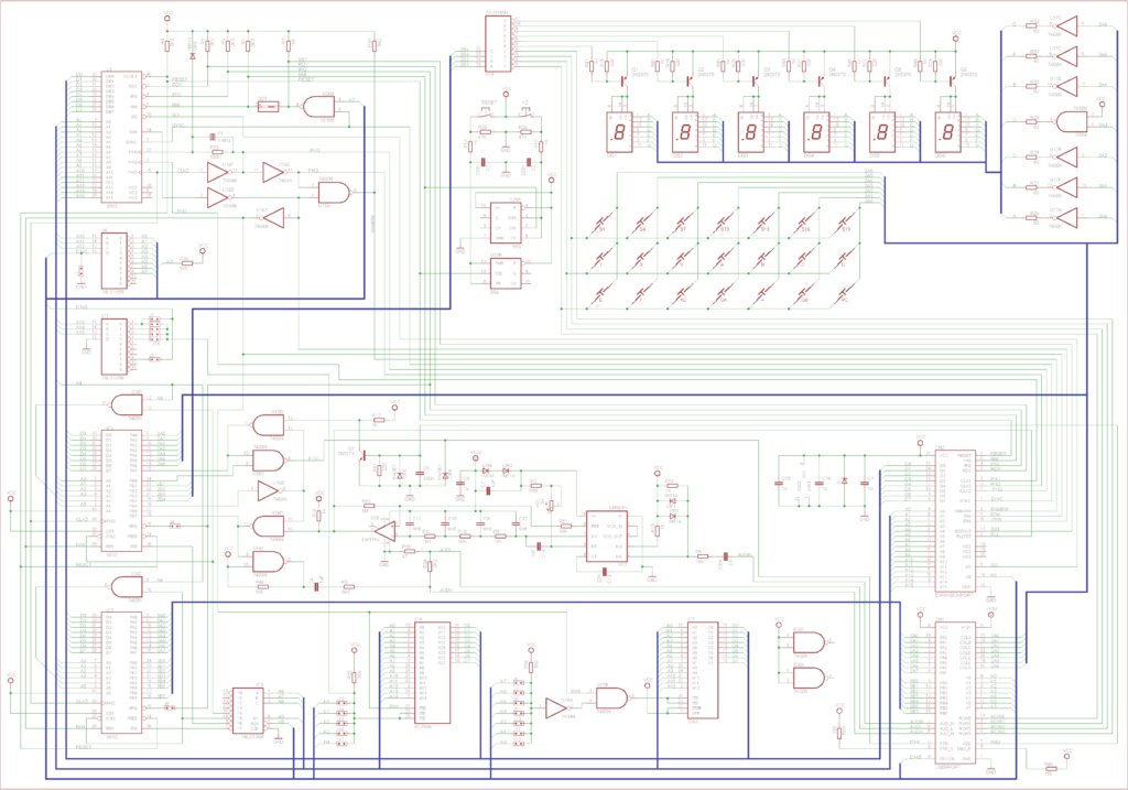
What are the major differences with the original schematic?
- Replacement of the 6530s by 6532s.
- Addition of two NAND gates to handle the 6532s.
- Addition of an EPROM.
- Replacement of the 6108 RAM ICs by a 62256 or equivalent 32K*8 SRAM.
- Addition of a 74LS138 to decode the RAM and I/O of the 6532s.
- The resistor for K6 has been dropped.
- Addition of jumpers to enable the combination of other K lines.