When I acquired a KIM-1 Rev A it came with some documentation revealing its provenance:
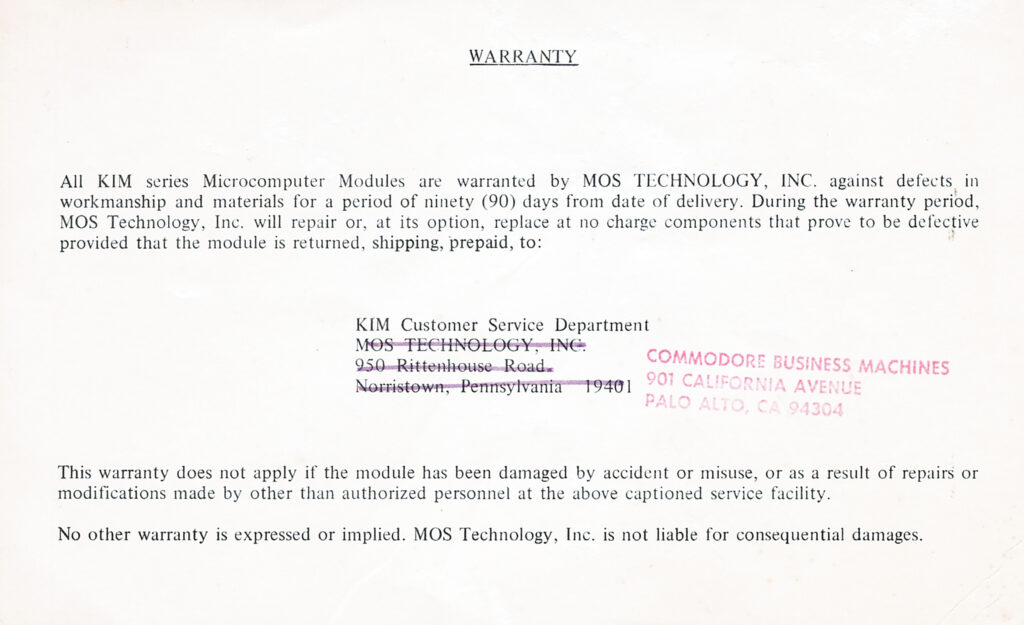
- Warranty card
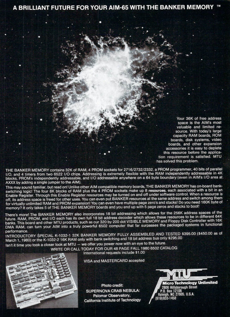
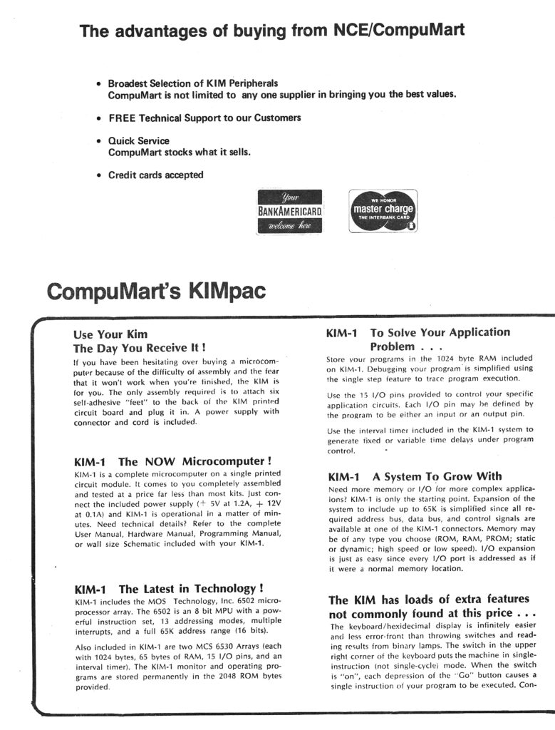
- Brochure showing the Rev A
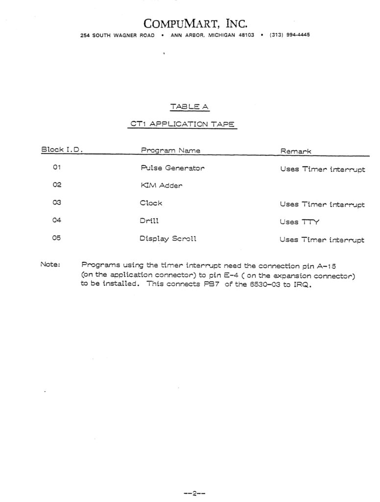
- A document with KIM-1 program called KIM-1 Application CT1
- KIM-1 Application Note 2 Interval Timer Operation
 |
KIM-1 Application Programs CT1 |
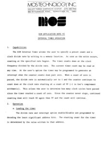 |
KIM-1 Application Note 2 Interval Timer Operation |
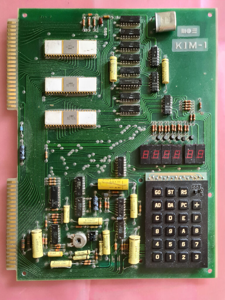
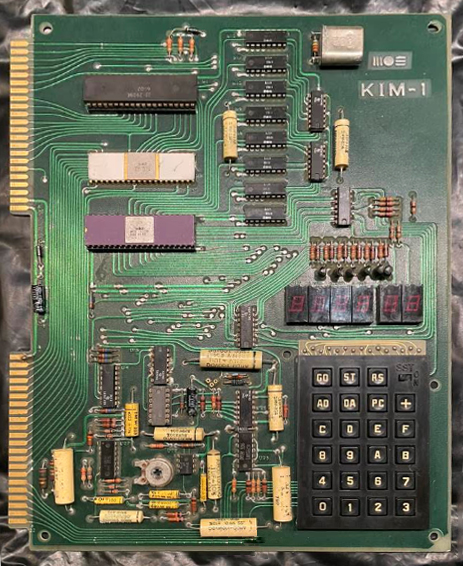
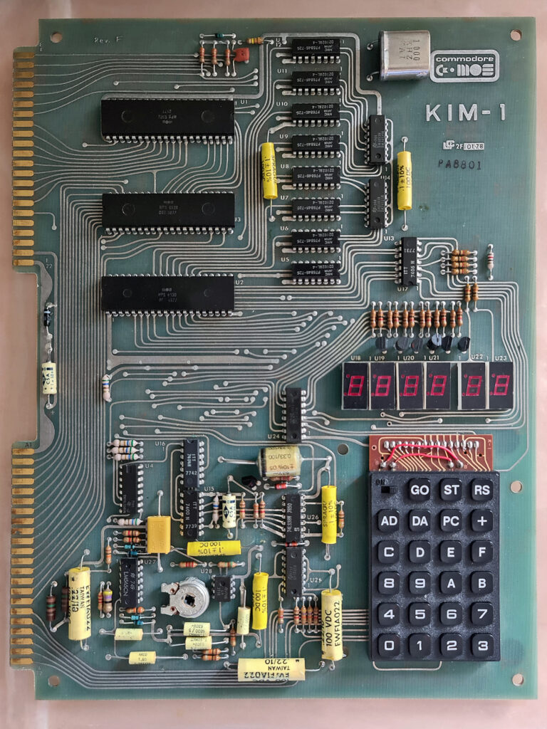
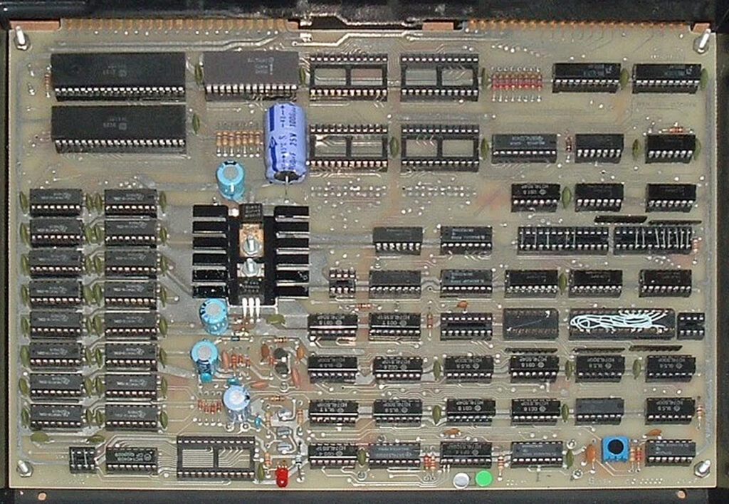
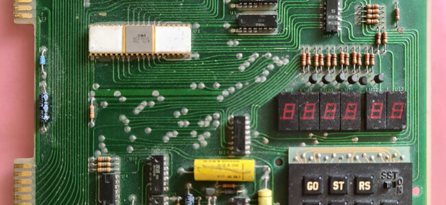
My Rev A CPU week 15 1976
See also:
TERC KIM-1 Interface set
A recent acquisition, the TERC (Technical Education Research Centers) KIM-1 Interface set. An educational tool to work w...
6502 tester NMOS CMOS 1-8MHz
The 6502 W65C02 6502C CPU tester NMOS / CMOS 1-8MHz is a CPU tester for 40 pin 6502/65C02 and WD65C02 and Sally.
The...
680x/650x Test system
The 680x/650x Test system allows to test, with the CPU itself performing the test, the MC680X and MCS650X families.
T...
Backbit Chip Tester PRO V2
A simple tio use and effective component test and ROM dump can be done with the wonderful Backbit Chiptester Pro V2.
...