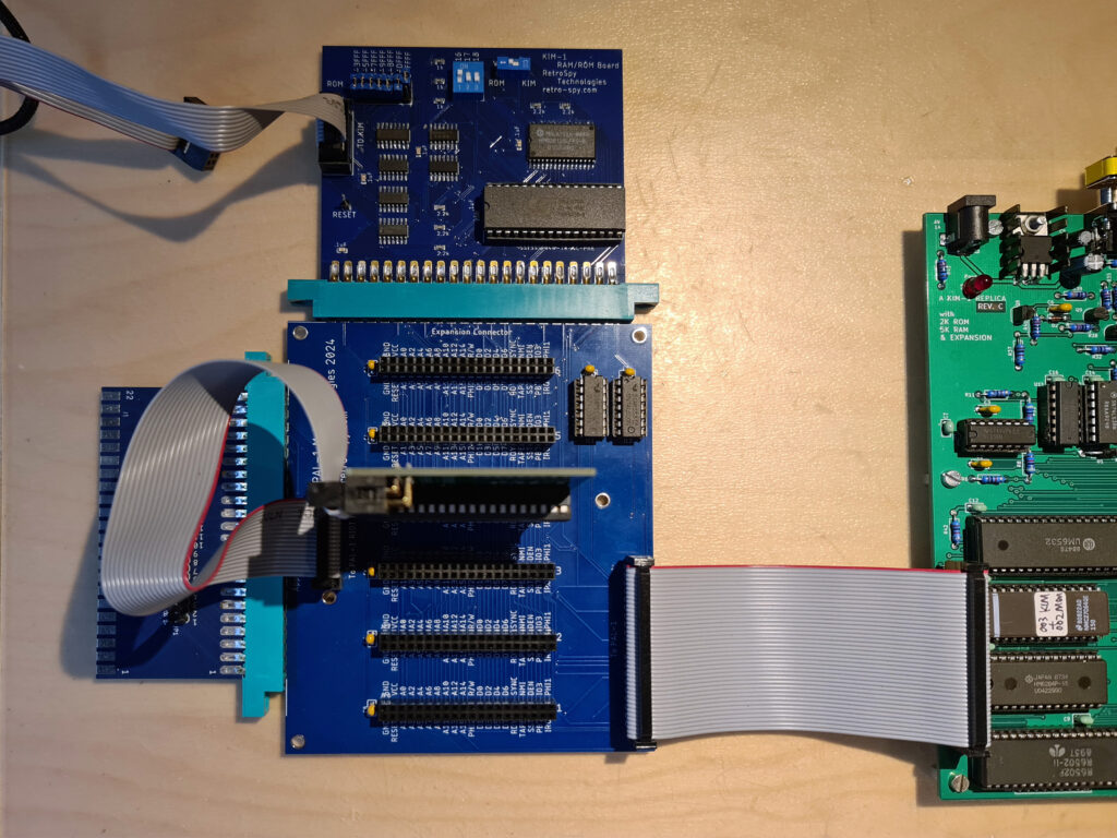
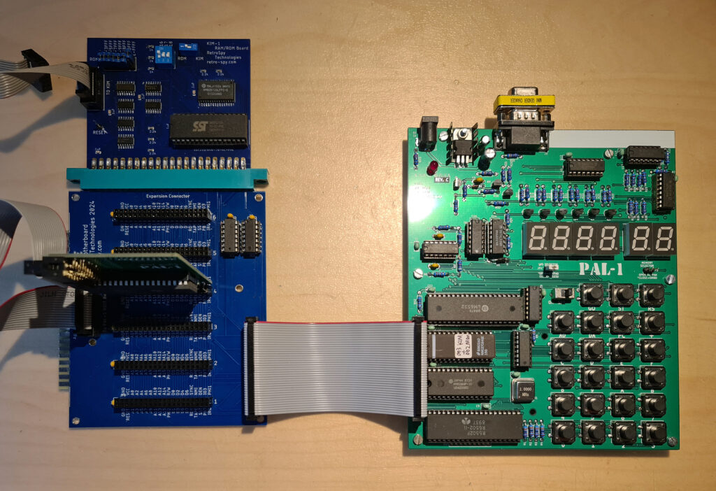
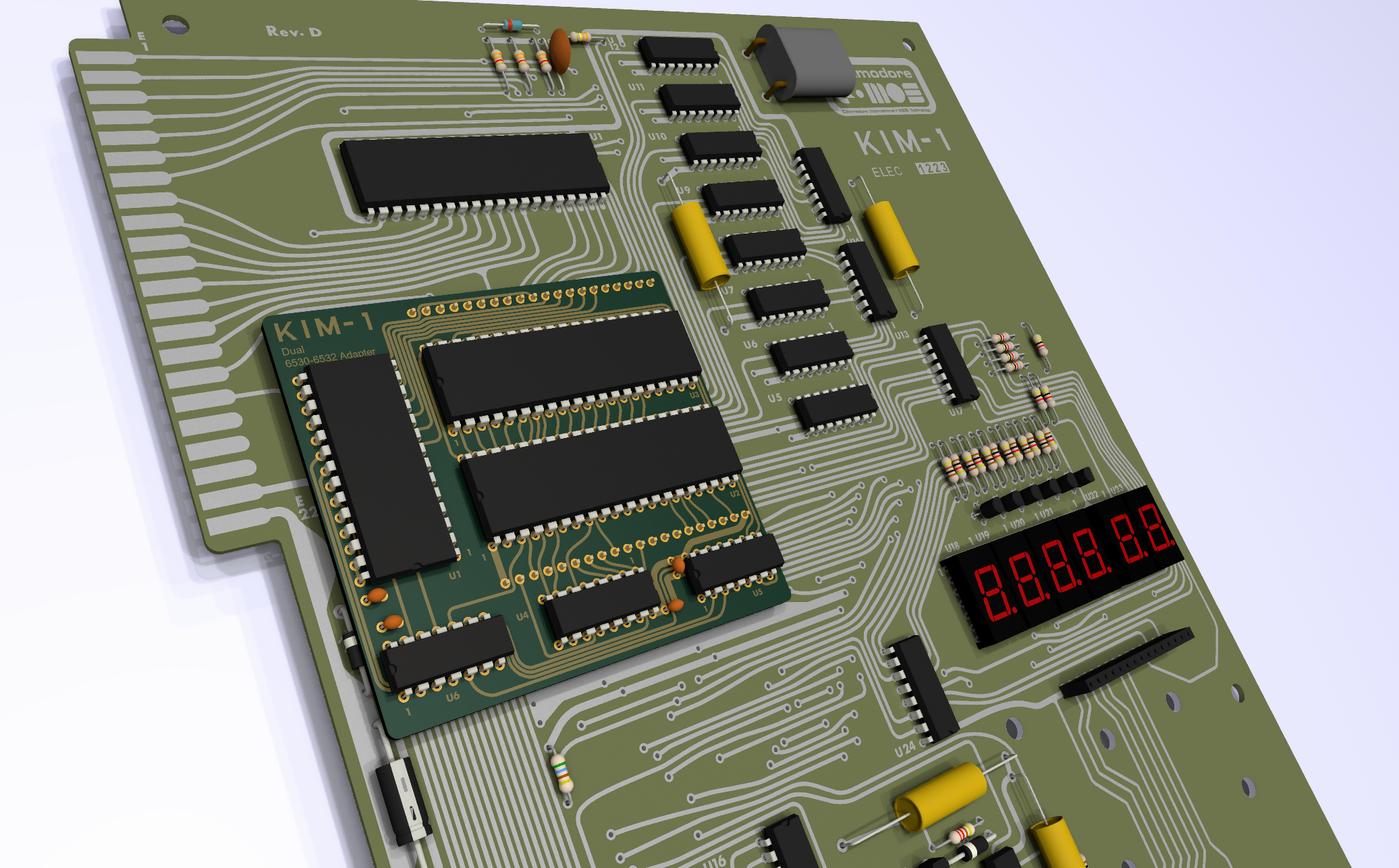
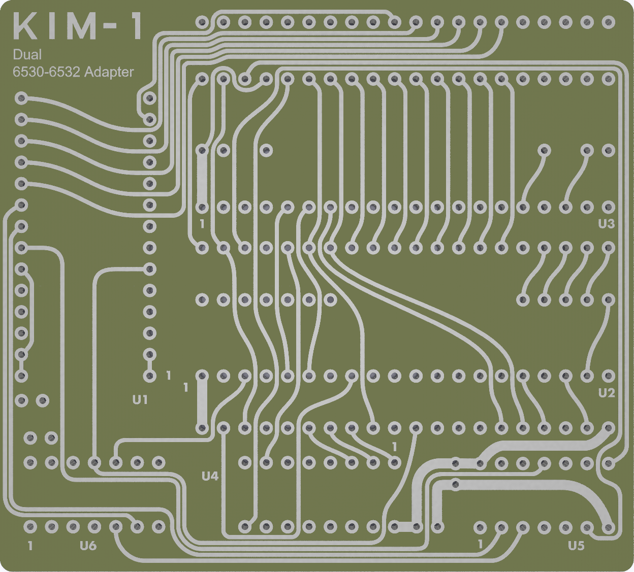
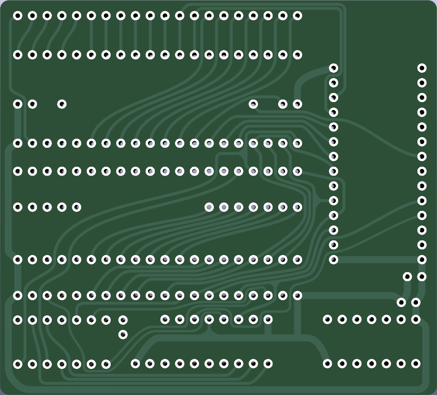
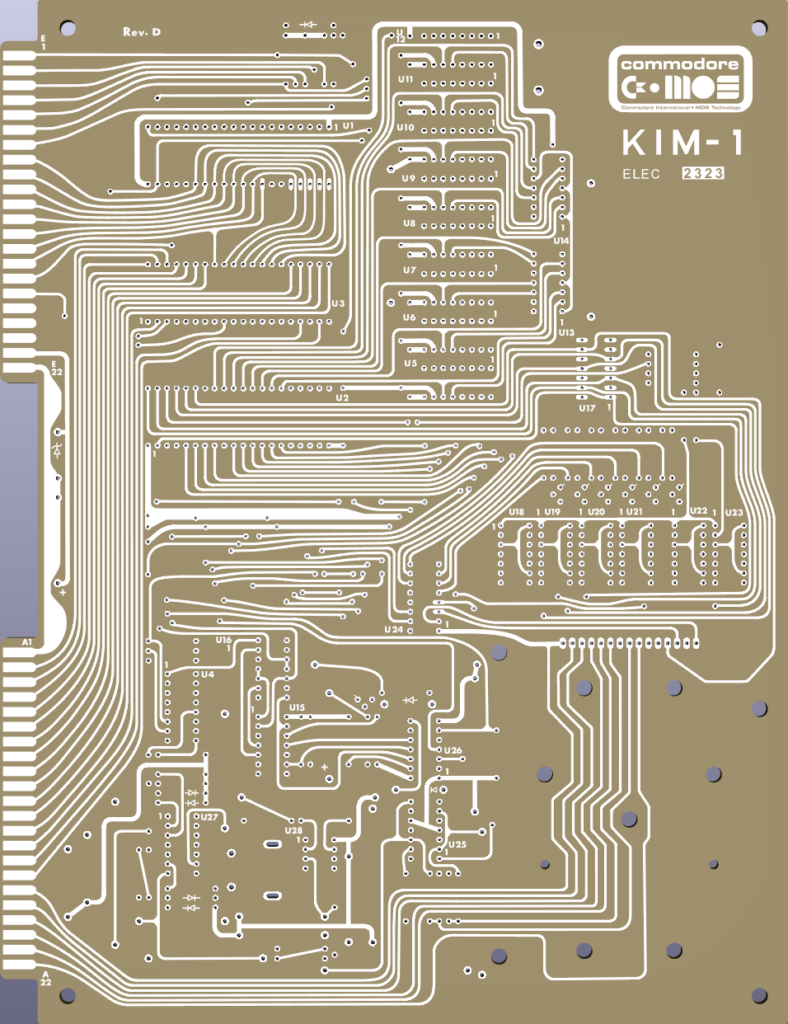
Colin Wolf (C. W. (chefkoch) ) posted a thread in 2021 on mikrocontroler.net showing a KIM-1 Replika he had build.
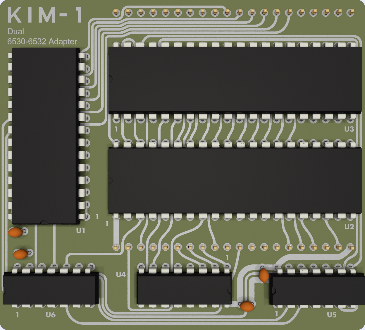
A KIM-1 with the dimensions and layout of the original KIM-1! OF course he used 6532 instead of the 6530-002 and -003, so a ROM was needed. To preserve the layout, this ROM was hidden as daughterboard on the back. The daughterboard also has the extra decoding circuit required for the 6532s. A very elegant solution!
Colin Wolf (C. W. (chefkoch) ) posted a thread in 2021 on mikrocontroller.net showing a KIM-1 Replika he had build.
A KIM-1 with the dimensions and layout of the original KIM-1! OF course he used 6532 instead of the 6530-002 and -003, so a ROM was needed. To preserve the layout, this ROM was hidden as daughterboard on the back. The daughterboard also has the extra decoding circuit required for the 6532s. A very elegant solution!
The text by Colin on the post: Hallo *,
wie bereits in dem Thread Beitrag “Fotos KIM-1 rev. F oder G”
angekündigt war ich dabei einen KIM-1 nachzubauen. Nach einigen
lehrreichen Stunden CAD-Fleißarbeit ist es nun vollbracht.
Es lebt!
Die beiden 6530 wurden durch 6532 ersetzt. Für die Umkodierung wurde der
Vorschlag unter
http://retro.hansotten.nl/6502-sbc/6530-6532/kim-1-6530-replacement/
benutzt und als Huckepackplatine realisiert. Der komplette
Funktionsumfang mit Audio- und Fernschreiberinterface ist also
vorhanden.
Photos reproduced here with permission from Wolfgang Robel. As you can see the end result is great, though he had to deal with broken 6532s from China and broken 2102 SRAM ICs.
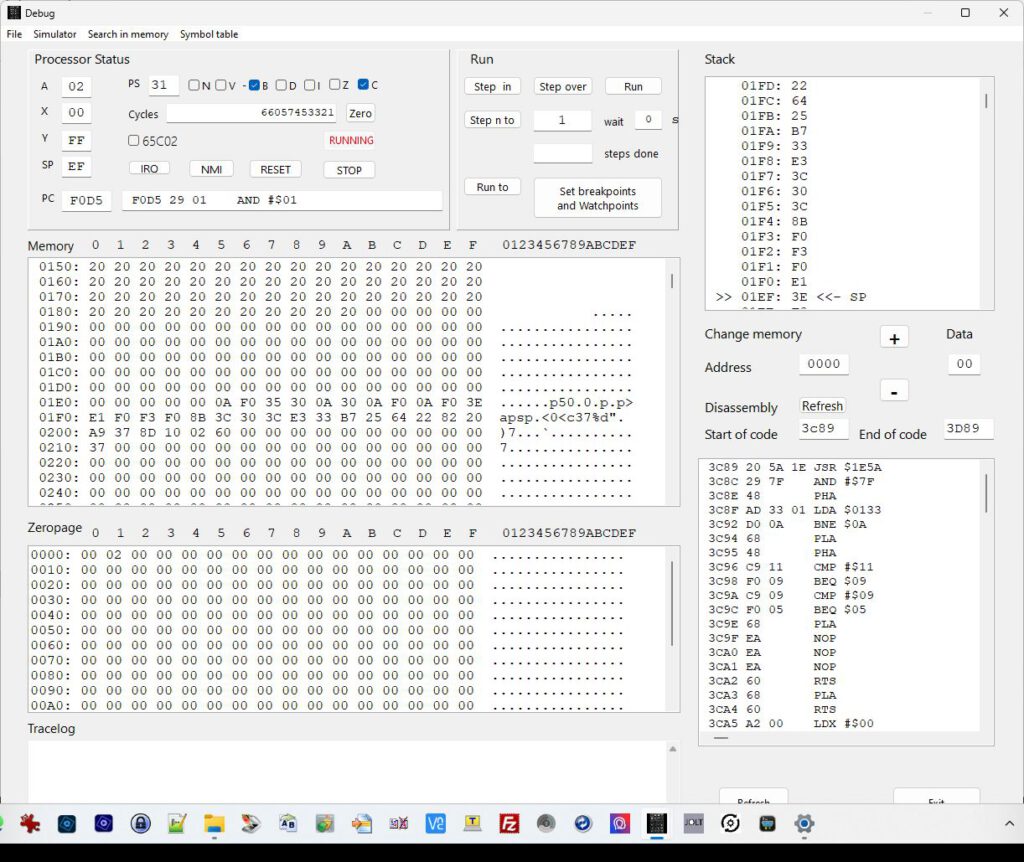
A complete 6502 Integrated Development Environment (IDE) for writing assembler source code, including editor, assembler, debugger and EEPROM programmer, see screenshot above.
The hardware comes with a 6502 micro-controller, 8 KByte EEPROM, 32 KByte RAM and an I/O interface based on an Intel 8255 PPI (Programmable Peripheral Interface), offering three 8-bit ports. The audio tape interface is realised by an NE565 PLL and the RS232 serial interface is based on a MAX232 IC
The built My-KIM computer has the following features:
A complete 6502 Integrated Development Environment (IDE) for writing assembler source code, including editor, assembler, debugger and EEPROM programmer, see screenshot above.
The hardware comes with a 6502 micro-controller, 8 KByte EEPROM, 32 KByte RAM and an I/O interface based on an Intel 8255 PPI (Programmable Peripheral Interface), offering three 8-bit ports. The audio tape interface is realised by an NE565 PLL and the RS232 serial interface is based on a MAX232 IC
Manfred extended a UNIX like console assembler to a window based 6502 Integrated Development Environment (IDE), offering the following features:
Loading, editing and saving 6502 assembler source code files
Assembling the source code and generating Intel Hex files as well as List files
Debugging the source code including break point definitions
Showing and editing the total 6502 memory area
Flashing the binary code to an 8 KByte EEPROM
It shall be mentioned, that the assembler can only be used for the early 6502 processors, but not for the 65C02 successor, having additional instructions not supported by this assembler.
Here the German text of the forum thread.
da Winter, Corona mit sozialen Einschränkungen und Rentnerdasein auf den gleichen Wochentag fielen, habe ich beschlossen, den KIM-1 Single-Board Computer basierend auf dem 6502 Prozessor nachzubauen. Dieses Board hatte ich 1977 gekauft und mit dynamischen RAMs, Tastatur und TV-Monitor sowie Microsoft BASIC aufgemotzt. Damit war ich der einzige an der Uni, der einen eigenen Computer besaß. Die Kommilitonen durften weiterhin mit Lochkarten die CDC-6000 bestücken. Leider ist das Unikat irgendwann auf dem Wertstoffhof gelandet.
Beim Nachbau habe ich soweit wie möglich die gleichen Bauteile verwendet, jedoch mit 32 KByte RAM und 8 KByte EEPROM aufgemöbelt. Darüber habe ich eine Integrated Development Environment (IDE) zum Editieren, Assemblieren und Debuggen von 6502 Assembler Source Code entwickelt, siehe My-KIM-IDE.exe (braucht keine Installation). Mit dieser IDE kann der KIM-1 Nachbau auch im sogenannten TTY Mode betrieben werden (RS232 mit USB Adapter). Außerdem kann Microsoft BASIC in der Version 1.1 aus dem Jahr 1977 (KB9.BIN) geladen werden und die Programme können auf dem PC gespeichert werden.
Das Projekt ist im attached ZIP File vollständig dokumentiert, siehe das 60-seitige My_KIM.pdf Dokument.
Ben Eater surprised us with his video hands-on series about a breadboard computer.
In many episodes, Ben showed how to build a very simple 6502 computer. Well explained, well executed. The result is a working computer!
You can either source the parts yourself or buy a complete kit from Ben Eater, see his website.
Make sure you buy quality breadboards.
Ben does a fabulous series of YouTube videos about wiring together this 6502 breadboard computer.
It really is extremely interesting and educational. I strongly recommend you watch the video series and consider supporting Ben’s Patreon.
You can buy a kit from Ben. Ben has put a lot of work into making these educational videos — I suggest you support him and his future endeavours by buying his kits from him.
To play and have some fun: visit this web browser based emulator.
Now seeing him building this computer is a lot of fun, and many have done it. Do not pay attention to the grumpy old man at a certain 6502 related forum, the design and the build videos are fine and fit for beginners. It is a 1 MHz design, so no need for ultrafast logic IC’s.
Software
Ben limits software to simple examples, like how to show characters on the LCD or receive a charater via a bitbanged serial interface.
Below I present several ways to have the computer build on a PCB and let it do something useful, first an EHBasic one , the second a Tiny Pascal/assembler. Both require hardware additions.
Enhance Move the Ben Eater design to PCB
A breadboard computer is a nice start. Making it more permanent is a better solution once the experiments and modifications and additions are done and requires a PCB. And of the many appeared.
BenEaterPCB
First a simple and basic one. On the bolwire github page you find a nice designed PCB for the basic Ben Eater design. Nice features are the extra pins at 6502 and 65C22, which make testing easy. I have a PCB and plan to build the basic Ben Eater computer on it.
build by bolwire
PCB and EHBasic by mike42
Mike42 has published many blog entries on the 6502 computer he build, starting with a standard Ben Eater design on breadboard.
He then moved to a PCB design, added address decding and added software like the EHBasic interpreter from Lee Davison.
See the blog posts for a well explained and detailed Kicad design and EHBasic adaptation, some posts linked here. He also published on github his PCB design and sources and ROM binaries.
(I would advise to not use the WD65C51, but an older 65(C)51, since the WD part has a serious bug, and the trick to work with it wastes many CPU sycles.
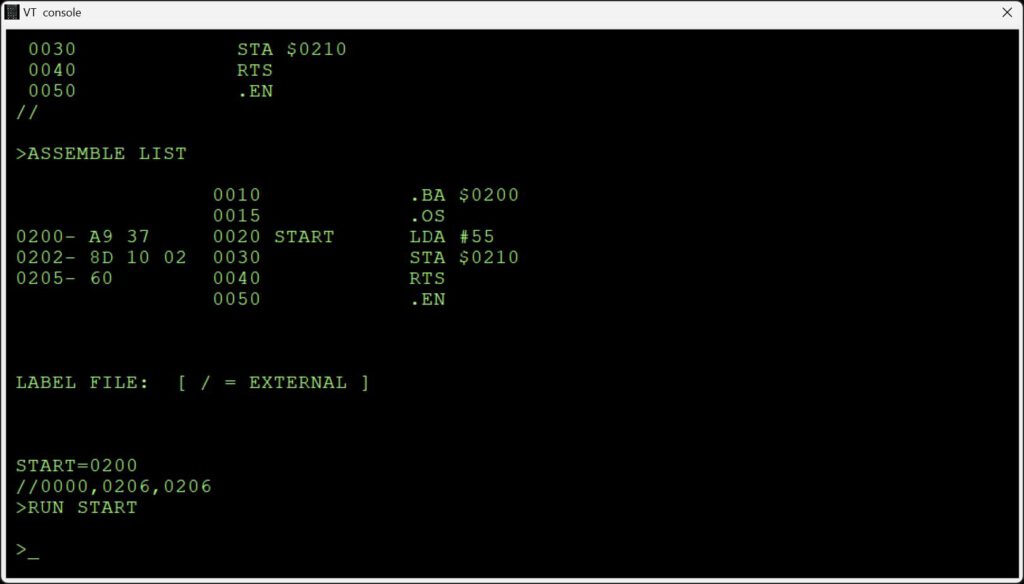
A 6502 assembler which lets you try out your assembler programming without having to keep removing the EEPROM chip and programming it externally. The assembler supports:
The documented WD65C02 instruction set, with all operand modes
Full expression evaluation of operands, with operator precedence, parentheses, bitwise operations and so on.
Relocation of the output to any memory address (ORG directive)
Support for debugging using breakpoints (BRK instruction)
Here is “hello world” in assembler:
jmp begin ; skip the message
hello asciiz "Hello, world!"
begin:
lda #<hello
ldx #>hello
jsr print
rts
Detailed notes about the assembler.
A “tiny” Pascal compiler (G-Pascal) which allows you to program the board in a high-level language. Whilst there are limitations in what can be done in a few KB of memory, the compiler supports:
CONST, VAR, FUNCTION and PROCEDURE declarations
Local declarations (functions and variables within functions, etc.)
Logical operations: and, or, shift left, shift right, exclusive or
INTEGER and CHAR data types. (Integer are 3 bytes and thus range from 8388607 to -8388608)
Arrays
Interface with any memory address by using the MEM and MEMC constructs (to peek and poke memory locations)
Built-in functions to write to the LCD display.
Built-in functions to do pinMode, digitalRead and digitalWrite, similar to the Arduino. These interface with any available ports on the VIA chip.
Here is “hello world” for the LCD display:
begin
lcdclear;
lcdwrite ("Hello, world!")
end.</code>
And for the serial monitor:
begin
writeln ("Hello, world!")
end.
Detailed notes about the compiler .
A text editor for keying in programs. It supports:
Loading and saving (via the RS232 interface)
Inserting and deleting lines
Find and replace
Detailed notes about the editor and how to load and save source.
Available actions:
List/SAve line_number_range
Delete line_number_range
Insert/LOad after_line
Find line_number_range /target/flags
Replace line_number_range /target/replacement/flags
Help
INfo
Memory first_address last_address
Compile/Syntax/Assemble
RUn/DEBug/Trace/RESume
Poke/Jsr/JMp
RECover
(Actions may be abbreviated)
(Flags: 'I'gnore case, 'G'lobal, 'Q'uiet)
Support functions, such as:
RS232 interface for connecting a “dumb” terminal, or a PC/Mac
Support for the LCD interface described in Ben’s videos
Other support functions for use by your assembler code, such as multiplication and division, CRC calculations, binary-to-decimal conversion
Support for NMI (non-maskable interrupts) so that you can recover from runaway code
Support for I2C communication for connecting to real-time clocks, port expanders, etc.
Support for SPI communication for connecting to port expanders, display boards and other devices.
There is over 9k of space available on the EEPROM to add your own functions (over 11k if you omit the CP437 character set from it)
Both the Pascal compiler and assembler are quite fast. Any program that will fit into memory will compile in a few seconds. For example, using a 1 MHz clock:
A 335-line assembler program testing all opcodes assembles in 5 seconds
A 651-line G-Pascal program (the Adventure game) compiles in 6 seconds
I reported some time ago about a new based upon the Elektor Junior design, by Jörg Walke, the Junior Computer ][.
Junior Computer ][ Main board
In the meantime the Junior ][ has grown up. A Bus card and an Interface card with a lot of functionality has been designed by Jörg, the software has also been updated with EHBasic and much more.
In May 1980 the DIY project Junior Computer was presented in the Elektor electronics magazine.
The little single-board computer was equipped with 1 KB ROM, in which the monitor program is located, 1 KB RAM (plus 128 bytes of RAM located in the 6532 RIOT), which, according to the authors, was more than enough at the time.
At the 40th anniversary of the computer, I decided to design a version with all features I wanted for the junior back in the 80s. The result is the Junior Computer ][ described here. It has 8KB ROM and a maximum of 128KB RAM. A additional serial RS232 interface and a simple sound output (as described in Junior Computer Book 2, from page 41) are also added. A 5V plug-in power supply with 2A should be sufficient. If external hardware needs to be supplied with voltage via the expansion connector, 3 Amps is recommended.
In order to be able to address the additional memory, the originally address decoding had to be extended. This is designed in such a way that the compatibility of the computer with the original Junior is preserved. An adaptation of the original monitor ROM to match the new memory location was not necessary.
Like its ancestor, the Junior Computer ][ can be expanded with external hardware via a 64-pin connection. The pin assignment oft he bus was largely retained.
In the new version, the 16 available port lines of the 6532 are available via 20-pin connector instead of a 31-pin connector.
The circuit changes mentioned here were made exclusively by me and expressly without the prior consent of the publisher Elektor, which is hopefully forgivable after 40 years. Of course, all rights to the original circuit design remain to Elektor and the authors.
Circuit diagrams, Gerber files, ROM images and other documents of the Junior Computer ][ (including this description) can be downloaded from https://old-computer-tech.net/downloads/ .
The computer and all its documents are published under the Creative Commons Attribution 4.0 license.
To test my new HDMI 4K USB Video Capture I made two videos. Simulator running on one notebook, the other notebook with the HDMI capture dongle recording with OBS Studio.
Simple program
[code]
0200 a9 cd LDA #$CD
0203 8D 00 03 STA $0300
0206 4C 00 1C JMP MONITOR ; KIM monitor
This page is a Work in Progress since November 2022!
The clones of the KIM-1 that appeared the last years have renewed the interest of the retro scene.
Old software is restored or typed in again and adapted to the current use of serial terminal emulators and cross assemblers instead of the hardcopy Teletype interface and native assemblers of the old days.
CPM-65, a CP/M-80 like operating system for 6502 based microcomputer
Dietrich Lausberg build a Junior long ago and expanded it to quite a system. He added hardware Elektor components, floppy and hard disk drives and wrote a CP/M inspired operating system, called CP/M-65. He still uses and maintains the system!