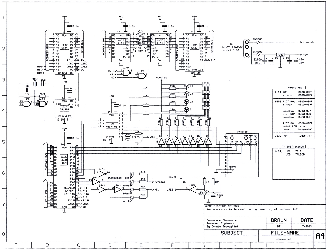
The Chessmate is a 6530 – KIM-1 like computer. Keyboard, LED display are used as in the KIM-1. Peter Jennings, who designed this chess computer with Commodore, build upon his Microchess 1. from the KIM-1, and used the extra ROM space to enhance it to Microchess 1.5: more chess features, a chess clock, sounds, dedicated keys, status LEDs.
The 6530-024 delivers the I/O and timer and RAM used by the Chessmate, the RRIOT ROM is used by the main ROM as a Chess openings book.
It will not be that difficult to ‘clone’ this chess computer with the information here. A 6532 can easily take the role of the 6530. A 6502 instead of a 6504, some SRAM, a 2732 or similar ROM. The ROMs are dumped, see below.
On this page:
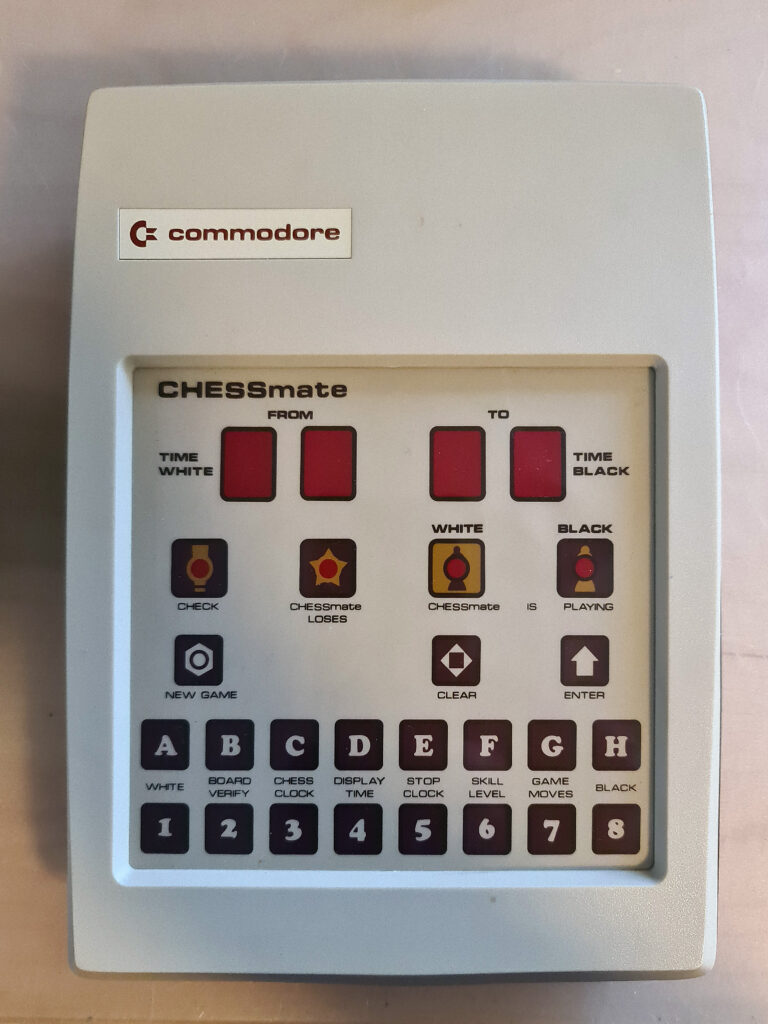
My Chessmate
Technical specifications
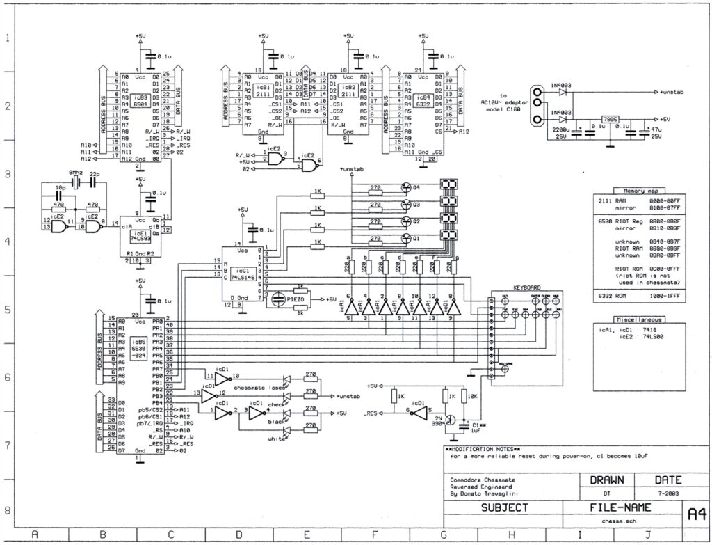
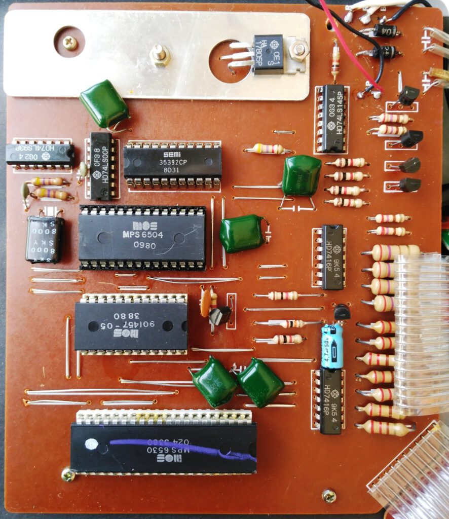
- MOS MPS 6504 1 MHz 4 KB ROM 320 bytes RAM total
- 6530-0024 RRIOT (of which I/O lines, timer and 64 bytes RAM are used, ROM has data as chess openings book
- 256 SRAM (2x 2111)
- 4K ROM (6332), early models have 2x 2K ROMs
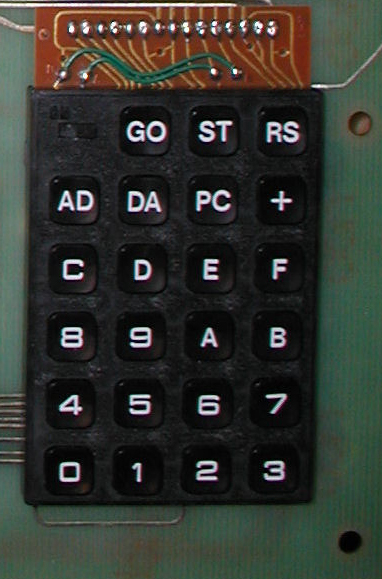
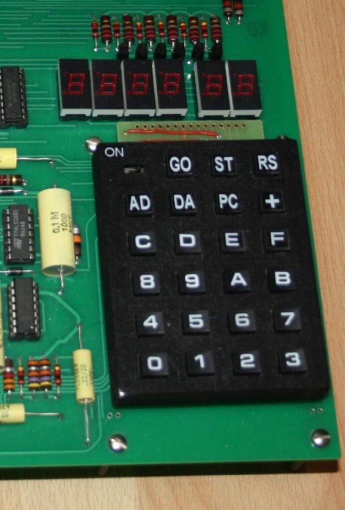
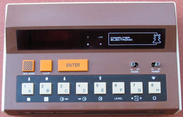
- Display: Four 7 Segment LED type (which indicates either the move or the time)
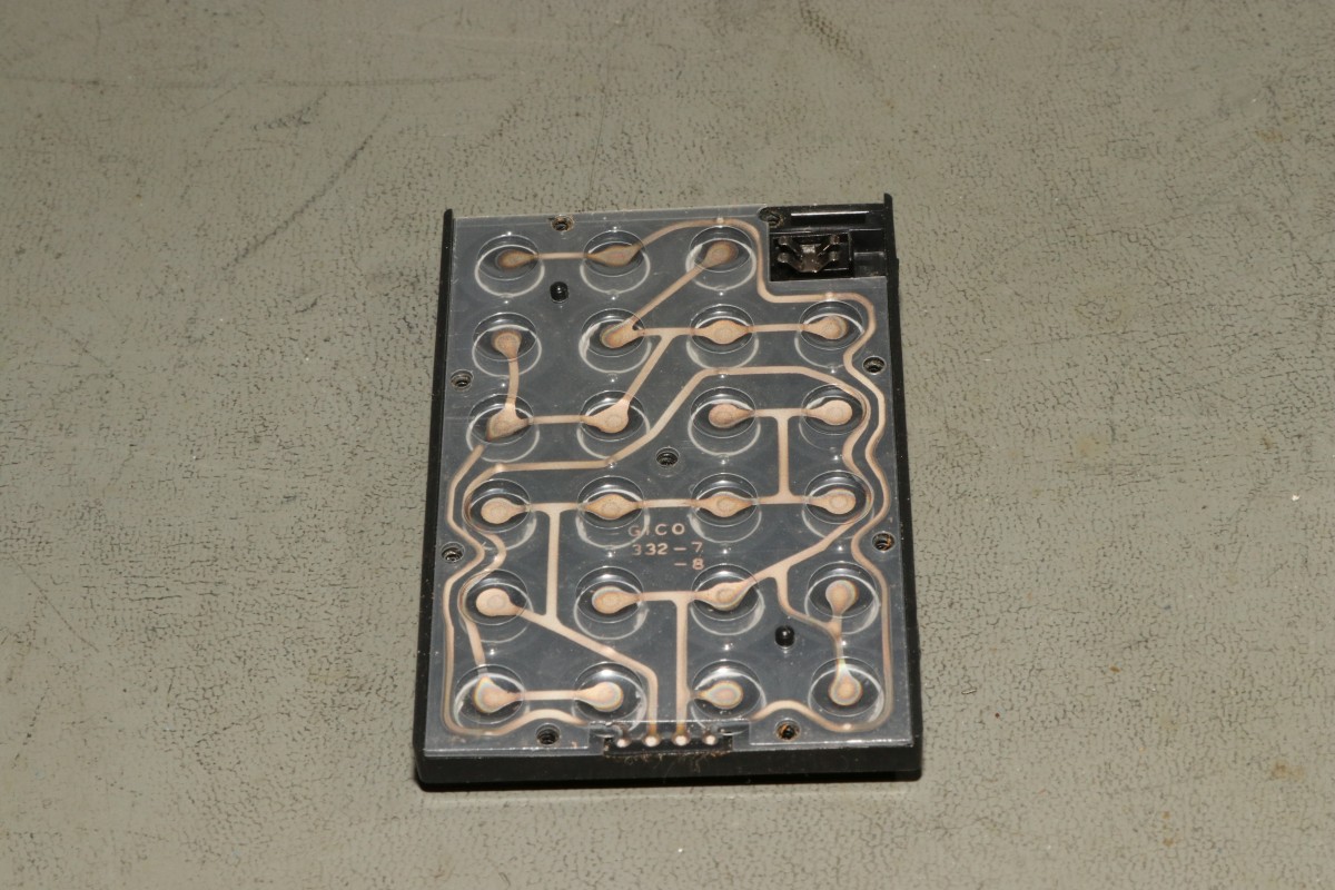
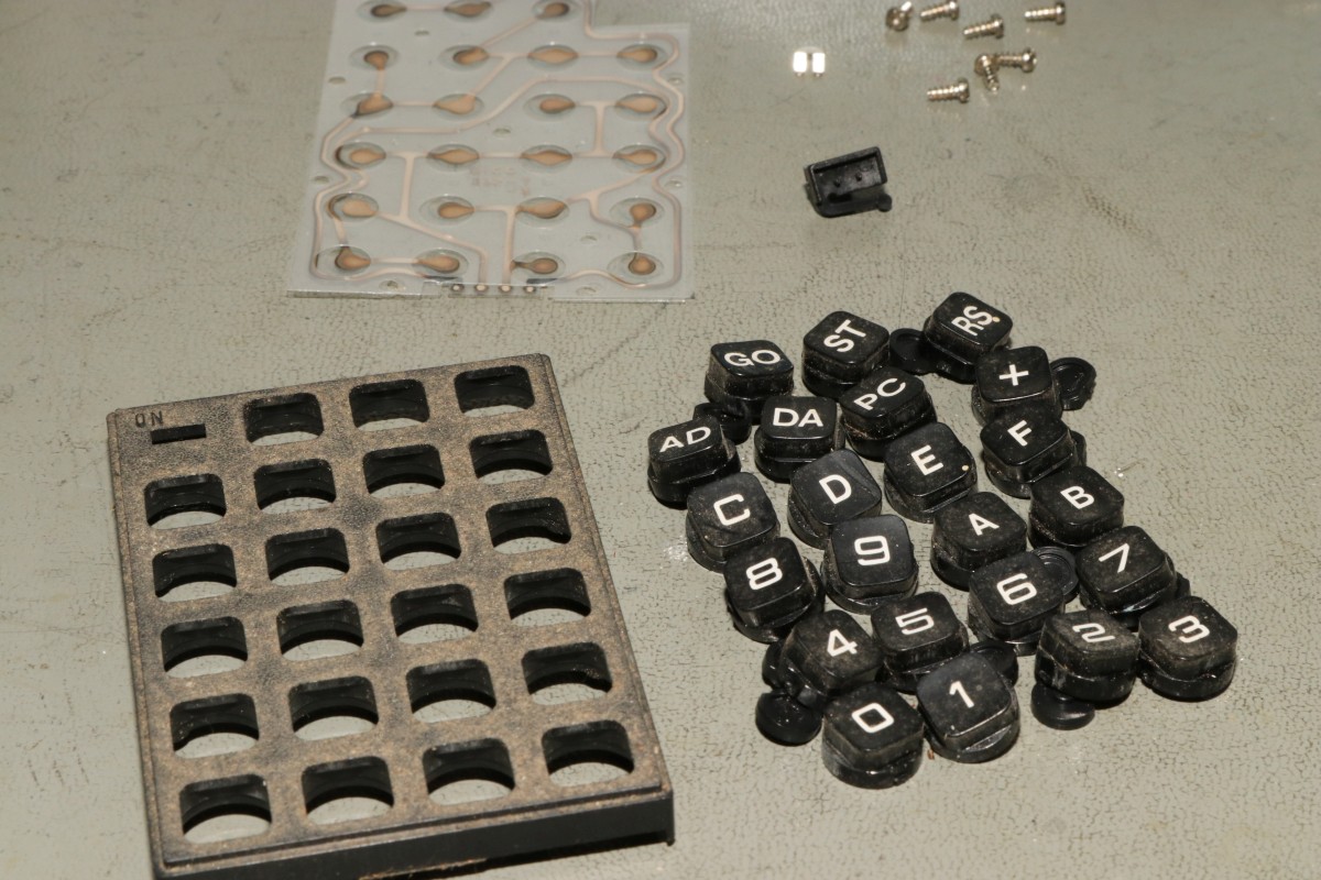
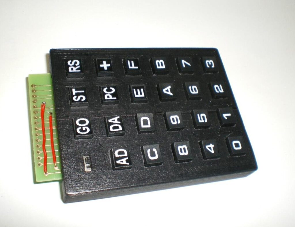
- 19 membrane keys
- LEDs for Check, Chessmate, or whether the computer is playing black or white
- Eight skill levels
- Piezo loudspeaker for 14 Electronic sounds
- Built-in chess clock
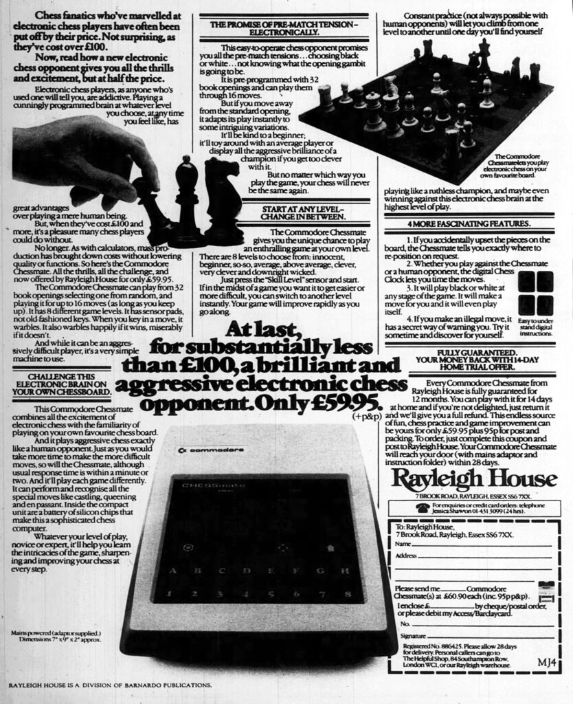
- The computer has 32 International standard openings in its memory and tries to follow them for 16 moves
- Chessmate plays black or white
- Can verify position of pieces at any stage of the game
- En passant and castling
- Playing strength (DWZ/ELO): ca. 1050
Related, identical specifications and hardware, and the same software, images below:
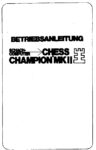
- Novag Chess Champion MK II (A)
- Novag Chess Champion MK II (B)
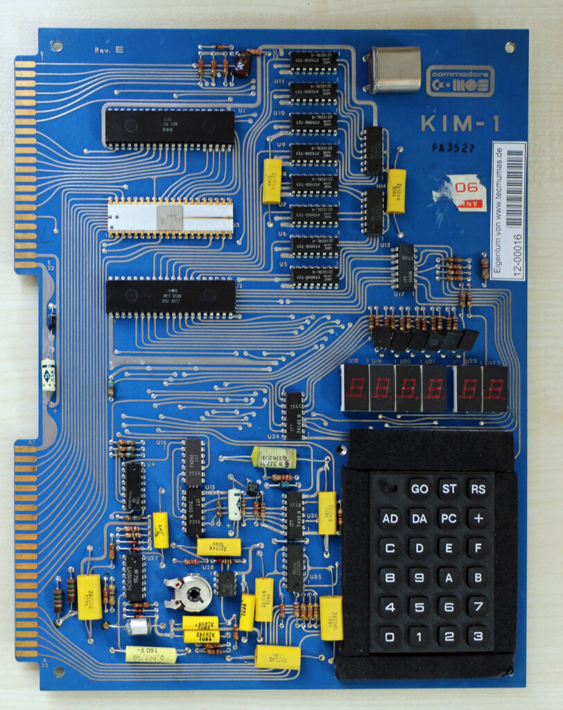
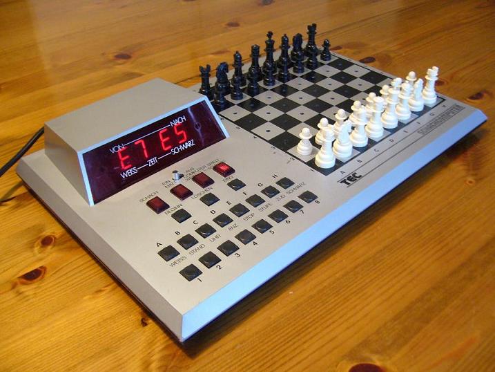
- TEC Schachcomputer
Memory map (deduced from disassembled source and hardware schematic, note that for the 6504 this is collapsed to the smaller address space 0000-1FFF. The software is written for the 6502 though!
$0000 – $01FF RAM 256 bytes, stack and zeropage mirrored
$8B00 – RRIOT I/O
$8B80 – RRIOT RAM 64 byte
$8C00 – $8FFF RRIOT ROM
$F000 – $FFFF Main ROM
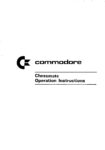
Manuals and ROM dumps
Notes on the 6530 024 RRIOT
Michael Gardi helped me discover the following about the use of the RRIOT in the Chessmate, comments added to the source:
1. The timer is used for the random selection of openings.
CKINT = $8B0E
F38D AD 0E 8B LDA CKINT
2. The openings are stored in the RRIOT 1K ROM at $8C00
3. The RRIOT Timer is also used to implement the CHESSmate chess clock mode, see the source.
Opening book deciphered
The Chessmate chooses at random an opening from the opening book, which is in the 1K ROM of the 6530 024 RRIOT.
The first thing that pops out is that 28 of the 32 openings start with either D2-D4 (10) or E2-E4 (18). That explains the very high percentage of the time that these occur when openings are randomly selected. The Operation Instructions explicitly states that CHESSmate chooses one opening at random and tries to follow it for 16 moves
Micheal Gardi deciphered the coding of the openings:
There are 32 bytes for each opening representing 16 moves. Even bytes represent start positions and odd bytes represent end positions. A pair of bytes make a move. Moves alternate between white and black starting with white. Each byte represents a position on the chess board. The high nibble is the rank (row 1-8) and the low nibble the is the file (column A-H).
col_table = ['H','G','F','E','D','C','B','A']
row_table = ['1','2','3','4','5','6','7','8']

with open("Opening Book.bin", 'rb') as f:
    buffer = f.read()

    # For each line.
    ent_file = []
    even = 0
    address = 0x8C00
    for i in range(0,len(buffer),2):
        if i % 32 == 0:
            ent_file.append("\n")
            ent_file.append(hex(address))
            ent_file.append(": ")
            address += 32
        # Assume bytes are contiguous.
        if (even % 2) == 0:
            ent_file.append(col_table[buffer[i]&0x0F]+row_table[buffer[i]>>4]+"-"+
                            col_table[buffer[i+1]&0x0F]+row_table[buffer[i+1]>>4] +", ")
        else:
            ent_file.append(col_table[7-(buffer[i]&0x0F)]+row_table[7-(buffer[i]>>4)]+"-"+
                            col_table[7-(buffer[i+1]&0x0F)]+row_table[7-(buffer[i+1]>>4)] +", ")
        even += 1
    ent_file.append('\n')

    # Output the result.
    with open("Opening Book Dump.txt", 'w') as f:
        f.write(''.join(ent_file))
Running that code delivers this
8c00: E2-E4, E7-E5, G1-F3, B8-C6, B1-C3, G8-F6, F1-B5, F8-B4, E1-G1, E8-G8, D2-D3, D7-D6, C1-G5, B4-C3, B2-C3, D8-E7
8c20: D2-D4, D7-D5, C2-C4, D5-C4, G1-F3, G8-F6, E2-E3, E7-E6, F1-C4, C7-C5, E1-G1, A7-A6, D1-E2, B8-C6, B1-C3, C5-D4
8c40: F2-F4, D7-D5, E2-E3, G8-F6, G1-F3, C7-C5, B2-B3, E7-E6, C1-B2, B8-C6, F1-B5, C8-D7, E1-G1, F8-D6, D2-D3, D8-C7
8c60: E2-E4, E7-E5, F1-C4, G8-F6, D2-D4, E5-D4, G1-F3, F6-E4, D1-D4, E4-F6, C1-G5, F8-E7, B1-C3, C7-C6, E1-C1, D7-D5
8c80: E2-E4, C7-C5, G1-F3, B8-C6, D2-D4, C5-D4, F3-D4, G8-F6, B1-C3, D7-D6, F1-E2, G7-G6, C1-E3, F8-G7, E1-G1, E8-G8
8ca0: E2-E4, C7-C5, B1-C3, B8-C6, G2-G3, G7-G6, F1-G2, F8-G7, D2-D3, E7-E6, C1-E3, D7-D6, G1-E2, C6-D4, E1-G1, G8-E7
8cc0: E2-E4, E7-E5, G1-F3, B8-C6, F1-C4, F8-C5, C2-C3, G8-F6, D2-D4, E5-D4, C3-D4, C5-B4, B1-C3, F6-E4, E1-G1, E4-C3
8ce0: G1-F3, G8-F6, C2-C4, C7-C5, D2-D4, C5-D4, F3-D4, E7-E6, B1-C3, F8-B4, C1-D2, E8-G8, E2-E3, B8-C6, F1-E2, D7-D5
8d00: E2-E4, E7-E5, G1-F3, G8-F6, F3-E5, D7-D6, E5-F3, F6-E4, D2-D4, D6-D5, F1-D3, F8-D6, E1-G1, E8-G8, C2-C4, C7-C6
8d20: D2-D4, G8-F6, C2-C4, E7-E6, G2-G3, D7-D5, F1-G2, D5-C4, D1-A4, B8-D7, A4-C4, A7-A6, G1-F3, B7-B5, C4-C6, A8-A7
8d40: E2-E4, G8-F6, E4-E5, F6-D5, D2-D4, D7-D6, C2-C4, D5-B6, F2-F4, D6-E5, F4-E5, B8-C6, C1-E3, C8-F5, B1-C3, E7-E6
8d60: D2-D4, F7-F5, C2-C4, E7-E6, G1-F3, G8-F6, G2-G3, F8-E7, F1-G2, E8-G8, E1-G1, D7-D5, B1-C3, C7-C6, C1-F4, D8-E8
8d80: E2-E4, E7-E5, G1-F3, B8-C6, F1-C4, G8-F6, D2-D4, E5-D4, E1-G1, F6-E4, F1-E1, D7-D5, C4-D5, D8-D5, B1-C3, D5-A5
8da0: D2-D4, G8-F6, C2-C4, E7-E6, B1-C3, F8-B4, D1-C2, B8-C6, G1-F3, D7-D6, C1-D2, E6-E5, A2-A3, B4-C3, D2-C3, D8-E7
8dc0: E2-E4, B8-C6, D2-D4, D7-D5, E4-D5, D8-D5, G1-F3, E7-E5, B1-C3, F8-B4, C1-E3, C8-G4, F1-E2, E8-C8, E1-G1, D5-A5
8de0: D2-D4, D7-D5, C2-C4, E7-E6, B1-C3, G8-F6, C1-G5, B8-D7, G1-F3, F8-B4, C4-D5, E6-D5, E2-E3, C7-C5, F1-D3, D8-A5
8e00: D2-D4, D7-D5, C2-C4, C7-C6, G1-F3, G8-F6, B1-C3, D5-C4, A2-A4, C8-F5, F3-E5, B8-D7, E5-C4, D8-C7, G2-G3, E7-E5
8e20: E2-E4, E7-E5, G1-F3, B8-C6, F1-B5, D7-D6, D2-D4, C8-D7, B1-C3, G8-F6, E1-G1, F8-E7, F1-E1, E5-D4, F3-D4, E8-G8
8e40: D2-D4, D7-D5, C2-C4, E7-E6, B1-C3, C7-C5, C4-D5, E6-D5, G1-F3, B8-C6, G2-G3, G8-F6, F1-G2, C5-D4, F3-D4, F8-C5
8e60: E2-E4, E7-E5, G1-F3, B8-C6, F1-B5, A7-A6, B5-C6, D7-C6, D2-D4, E5-D4, D1-D4, D8-D4, F3-D4, C8-D7, B1-C3, E8-C8
8e80: D2-D4, C7-C5, D4-D5, D7-D6, C2-C4, G7-G6, B1-C3, F8-G7, E2-E4, G8-F6, F1-E2, E7-E6, C1-G5, E8-G8, G1-F3, E6-D5
8ea0: E2-E4, E7-E5, G1-F3, B8-C6, D2-D4, E5-D4, F3-D4, G8-F6, B1-C3, F8-B4, D4-C6, B7-C6, F1-D3, D7-D5, E4-D5, C6-D5
8ec0: D2-D4, G8-F6, C2-C4, G7-G6, B1-C3, F8-G7, E2-E4, D7-D6, F2-F3, E7-E5, D4-D5, E8-G8, C1-G5, H7-H6, G5-E3, F6-H5
8ee0: E2-E4, C7-C6, D2-D4, D7-D5, B1-C3, D5-E4, C3-E4, C8-F5, E4-G3, F5-G6, H2-H4, H7-H6, G1-F3, B8-D7, F1-D3, G6-D3
8f00: D2-D4, G8-F6, C2-C4, E7-E6, G1-F3, B7-B6, G2-G3, C8-B7, F1-G2, F8-E7, E1-G1, E8-G8, B1-C3, F6-E4, D1-C2, E4-C3
8f20: C2-C4, G8-F6, B1-C3, E7-E6, E2-E4, C7-C5, G1-F3, B8-C6, D2-D4, C5-D4, F3-D4, F8-B4, D4-C6, D7-C6, D1-D8, E8-D8
8f40: E2-E4, E7-E5, G1-F3, B8-C6, F1-B5, G8-F6, E1-G1, F6-E4, D2-D4, F8-E7, D1-E2, E4-D6, B5-C6, B7-C6, D4-E5, D6-B7
8f60: E2-E4, E7-E6, D2-D4, D7-D5, B1-C3, G8-F6, C1-G5, F8-E7, E4-E5, F6-D7, G5-E7, D8-E7, D1-D2, E8-G8, F2-F4, C7-C5
8f80: E2-E4, E7-E5, D2-D4, E5-D4, D1-D4, B8-C6, D4-E3, G8-F6, B1-C3, F8-B4, C1-D2, E8-G8, E1-C1, F8-E8, F1-C4, D7-D6
8fa0: E2-E4, E7-E5, D2-D4, E5-D4, C2-C3, D4-C3, F1-C4, C3-B2, C1-B2, G8-F6, B1-C3, B8-C6, G1-F3, F8-B4, D1-C2, D7-D6
8fc0: C2-C4, E7-E5, B1-C3, G8-F6, G1-F3, B8-C6, E2-E3, D7-D5, C4-D5, F6-D5, F1-B5, D5-C3, B2-C3, F8-D6, D2-D4, C8-D7
8fe0: E2-E4, E7-E5, G1-F3, B8-C6, F1-B5, A7-A6, B5-A4, B7-B5, A4-B3, C6-A5, B3-F7, E8-F7, F3-E5, F7-E7, D2-D4, G8-F6

Images of Chessmates
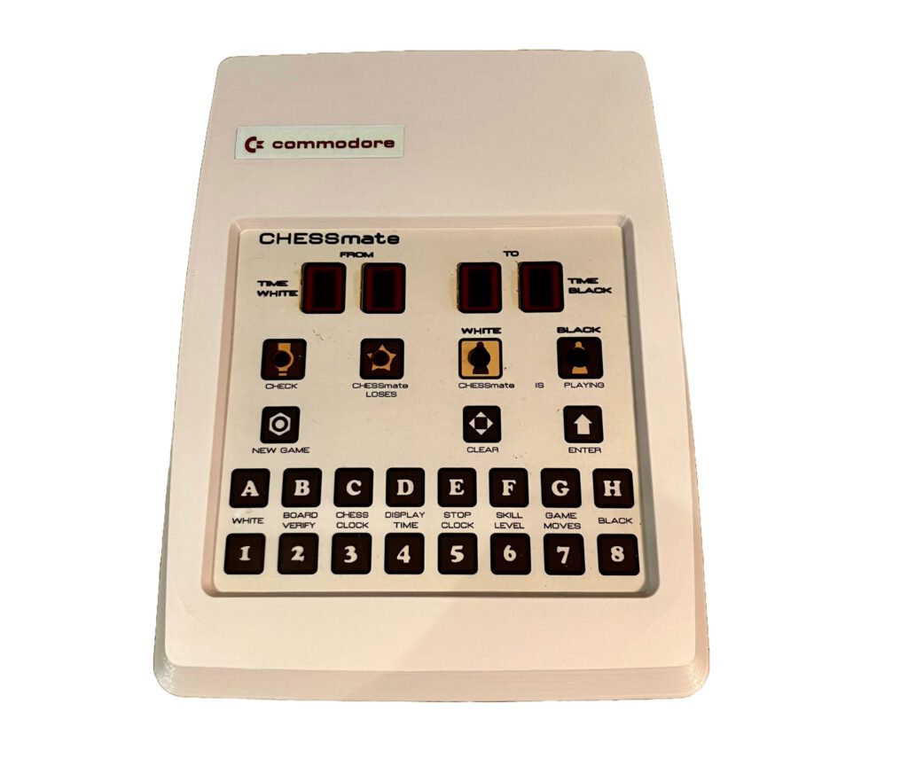
My Commodore Chessmate.
My Chessmate
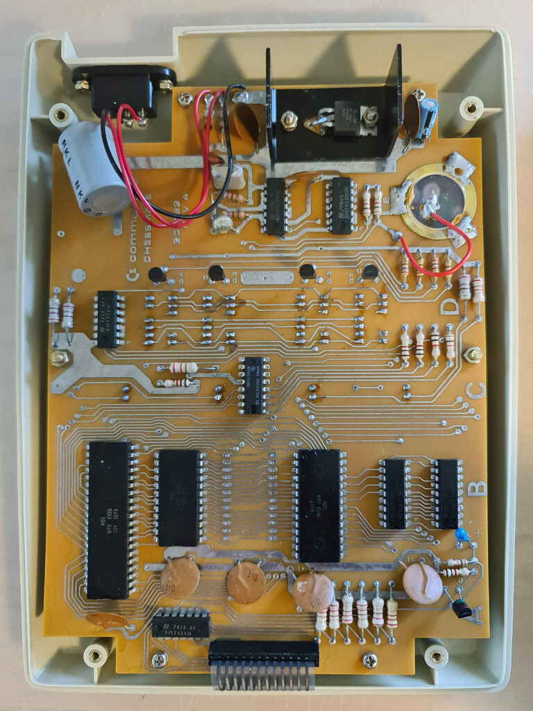
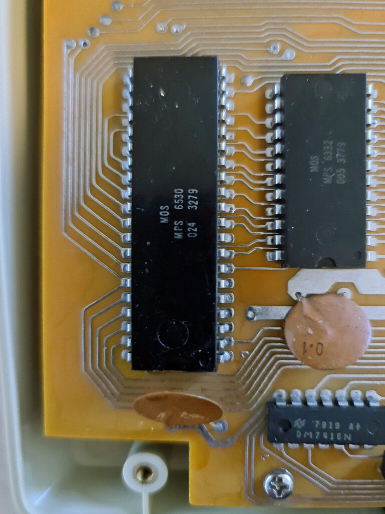
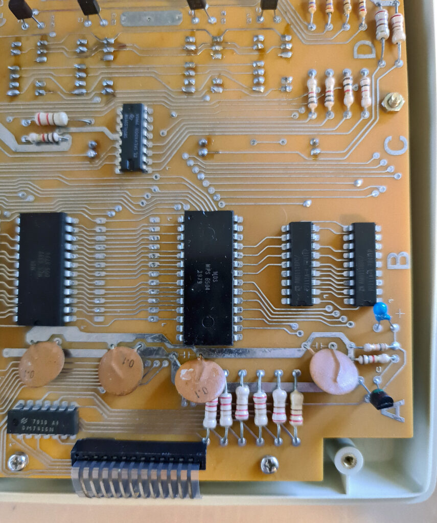
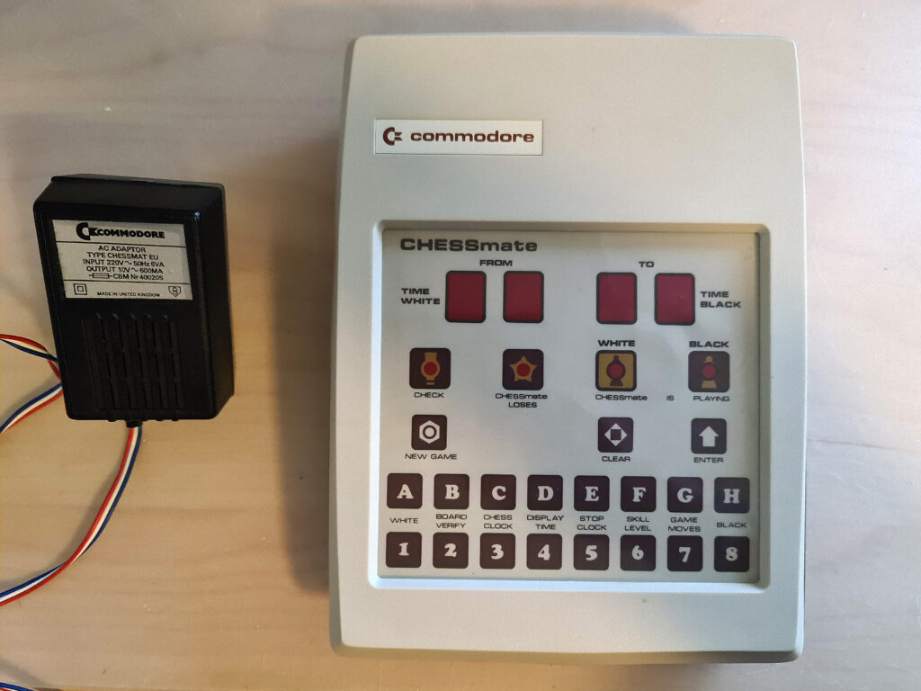
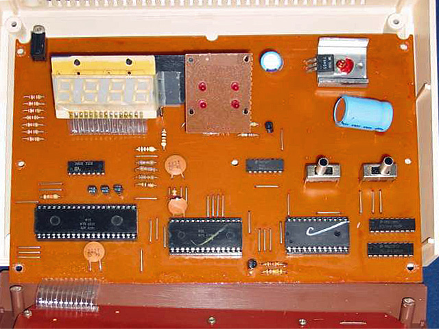
Photo by Commodore International Historical Society on twitter @commodoreihs
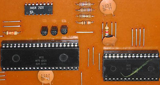
Photo by Commodore International Historical Society on twitter @commodoreihs
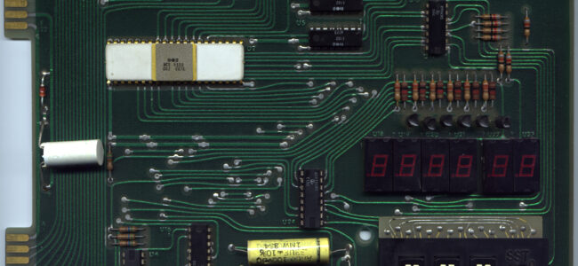
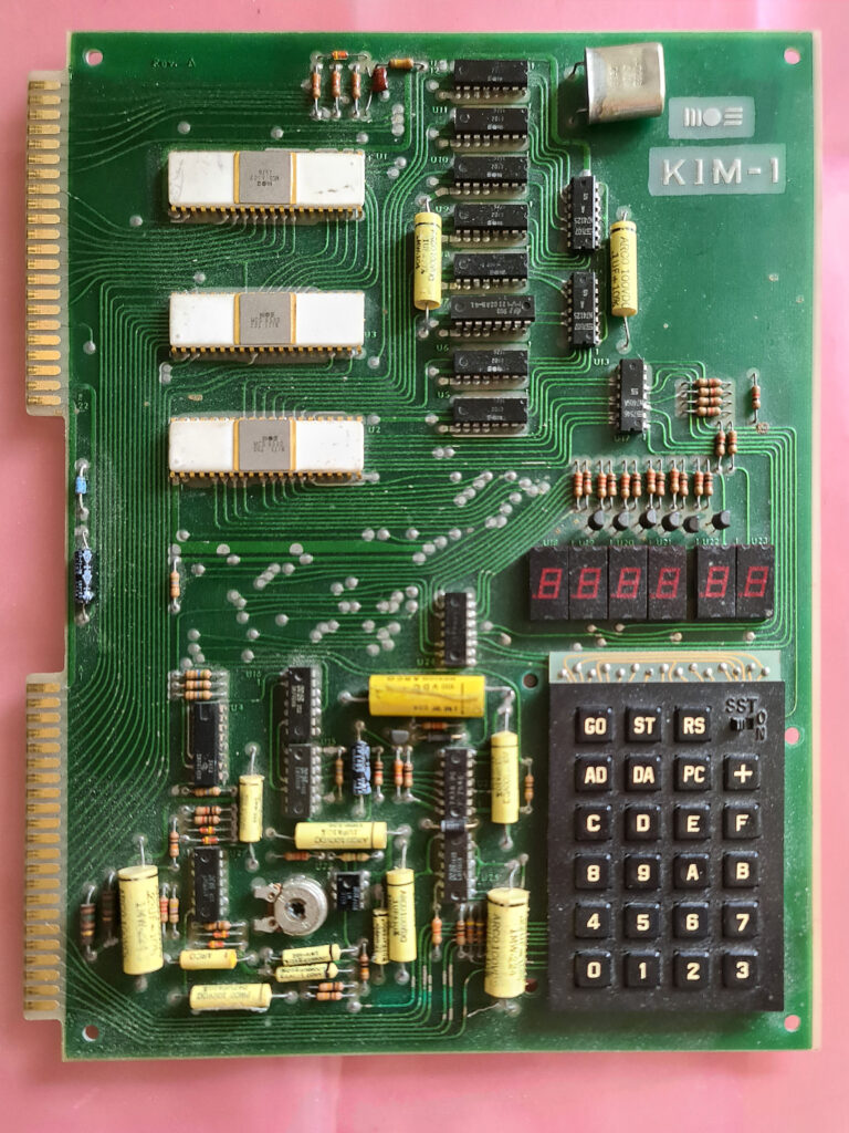
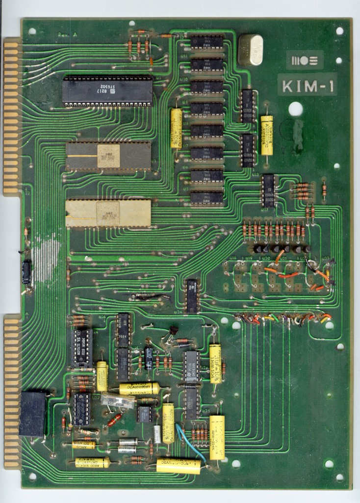
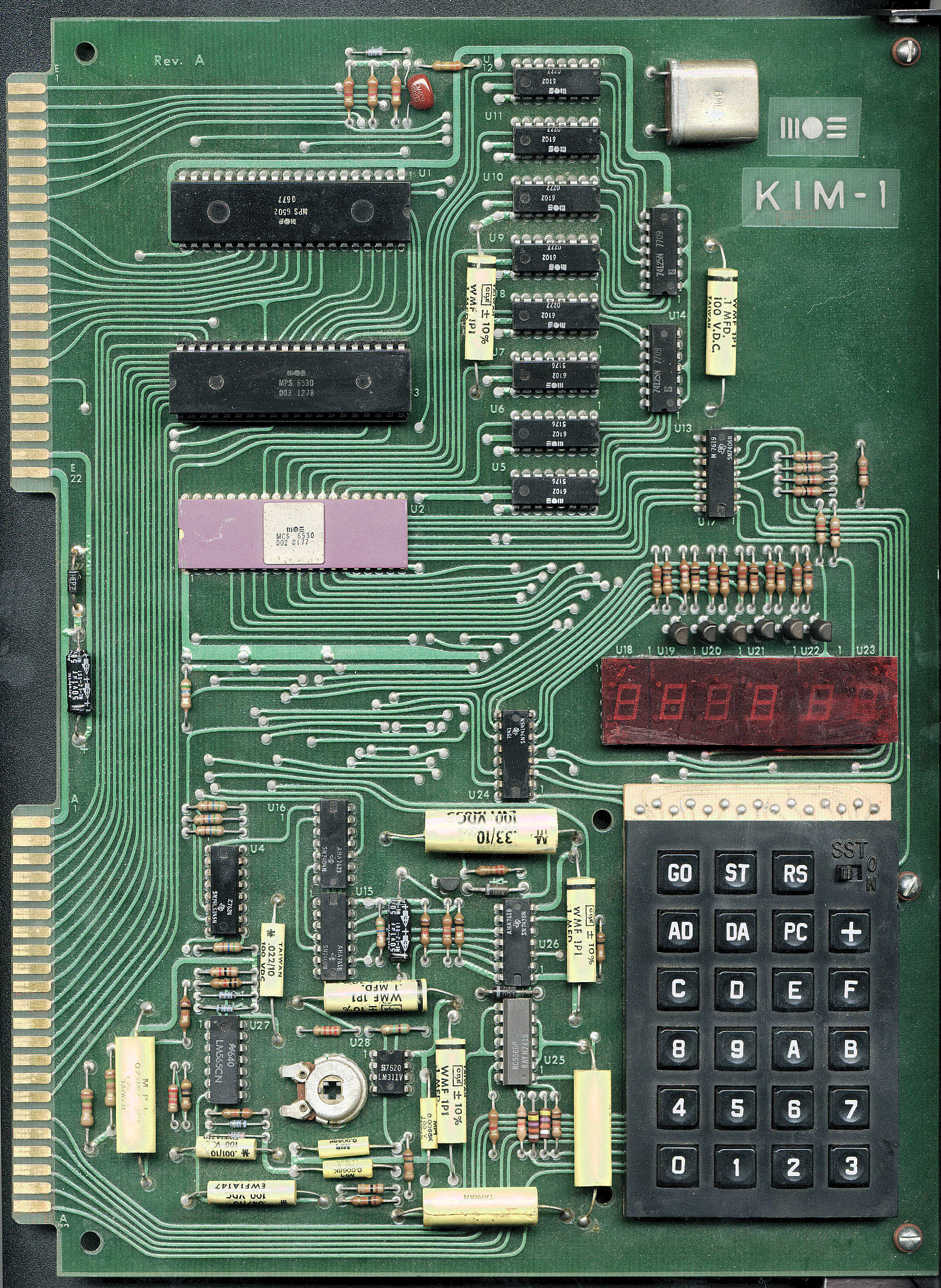
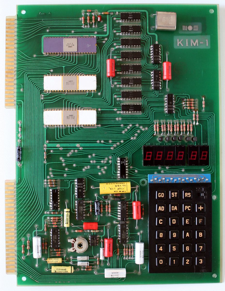
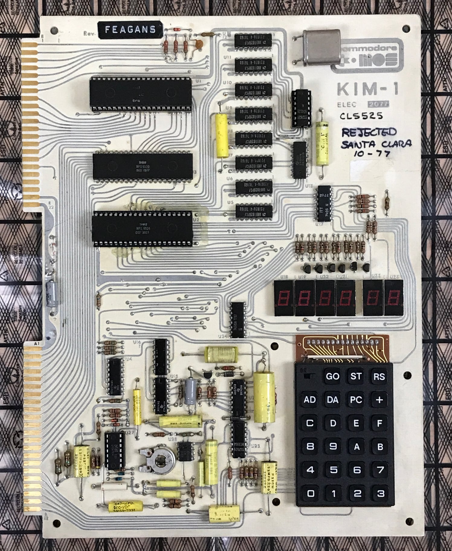
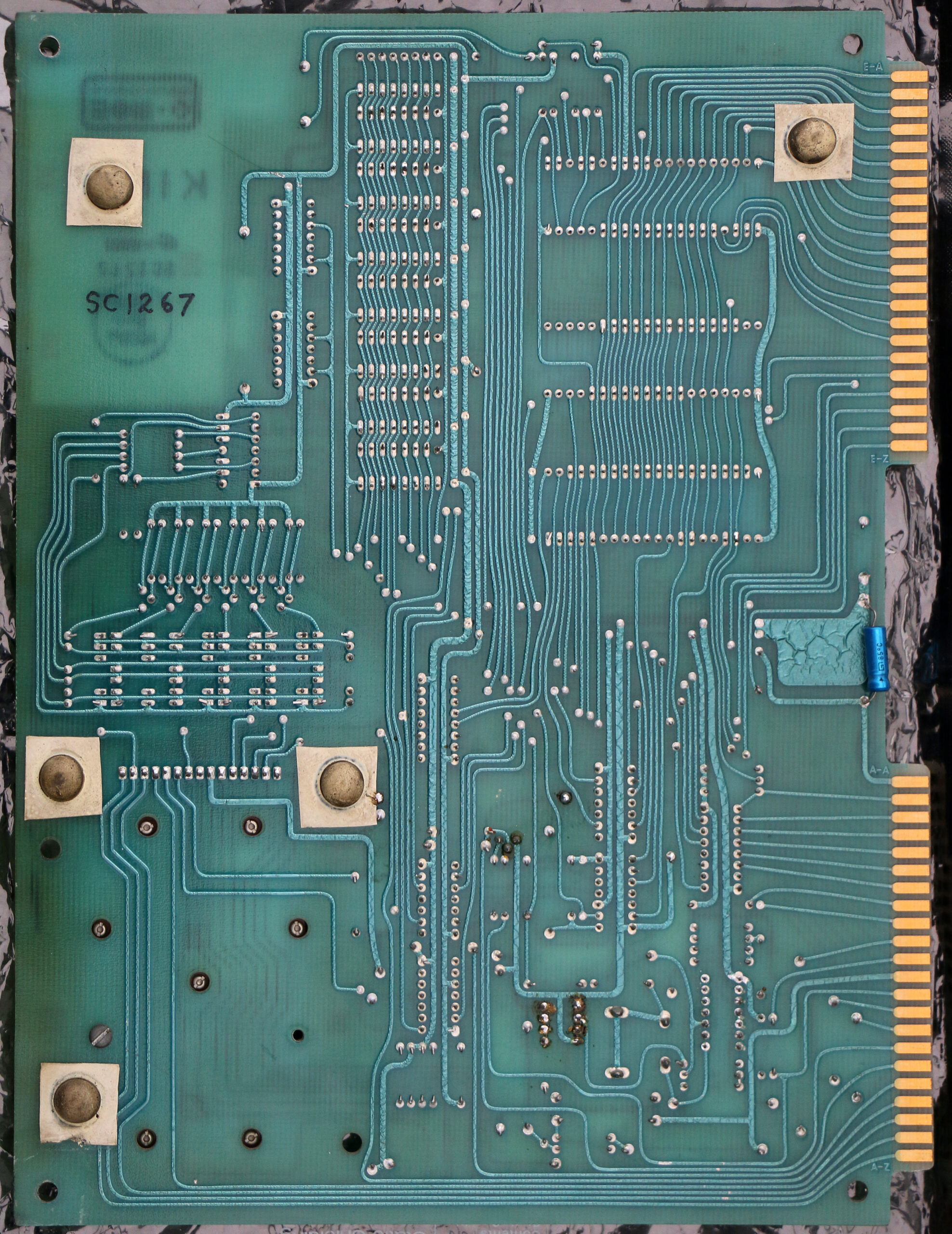
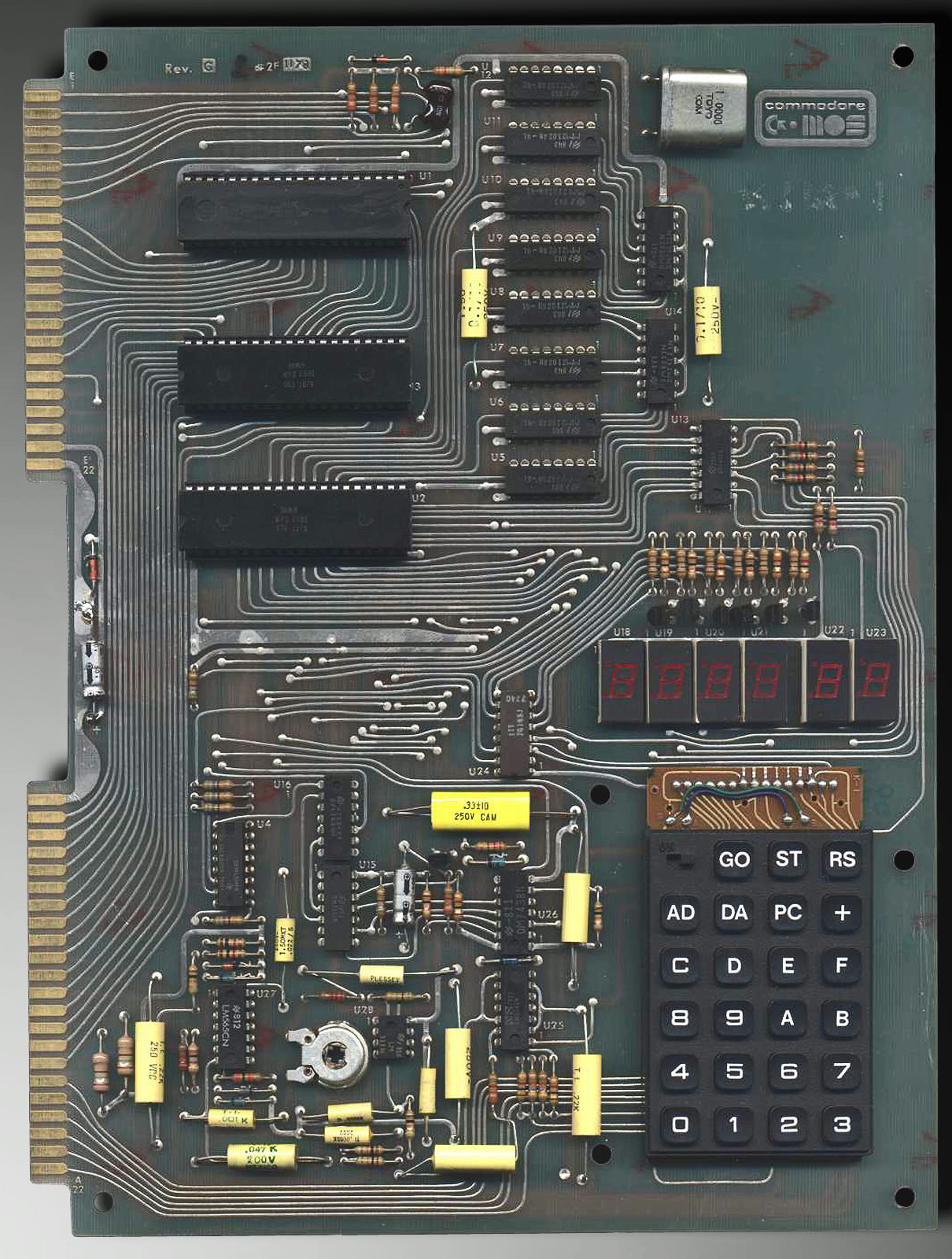
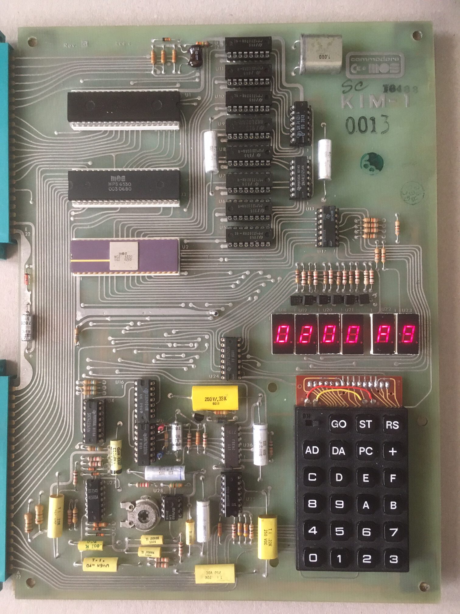
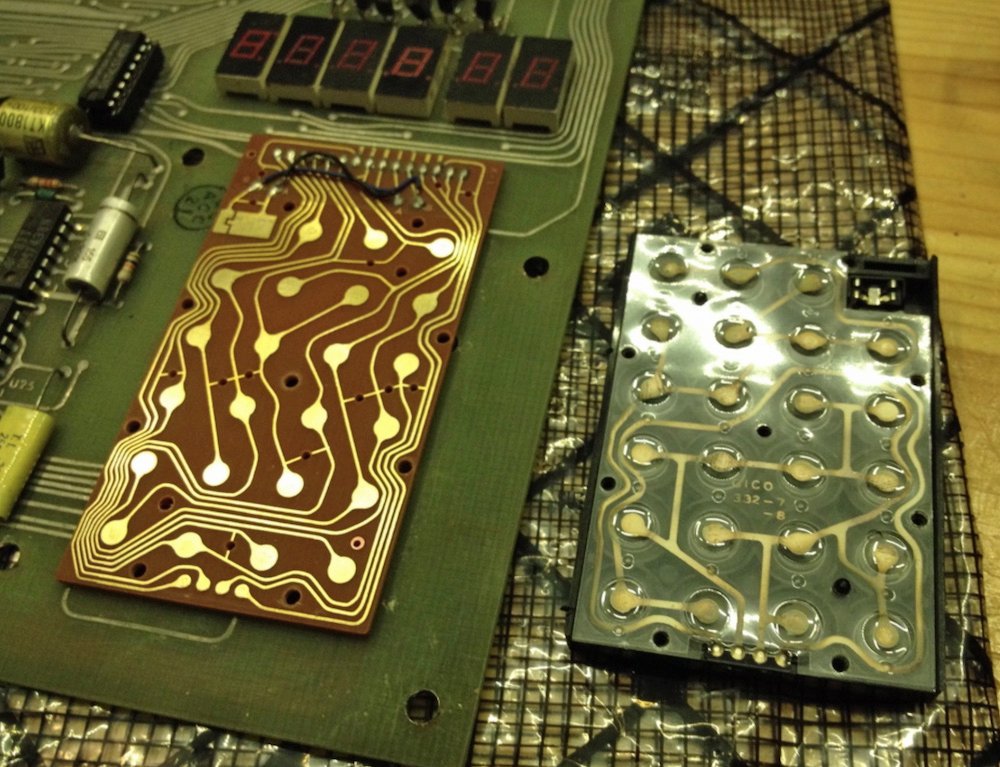
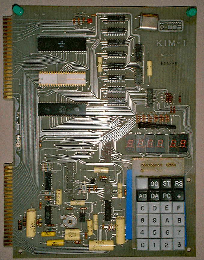
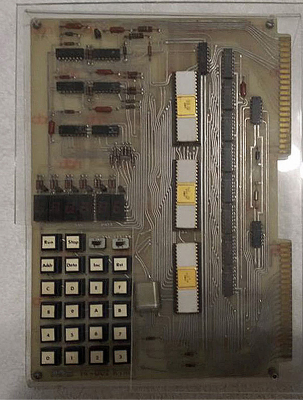
On this early Chessmate two ROMs were used, each 2K. The TTL IC on the top right was added manually and wire wrapped, the wires running from it to the ROM selection inputs.
Boxes
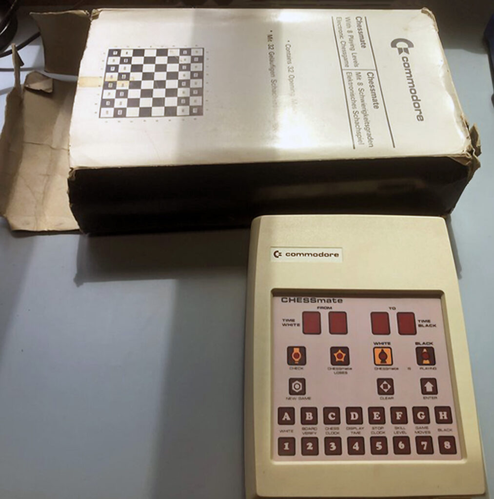
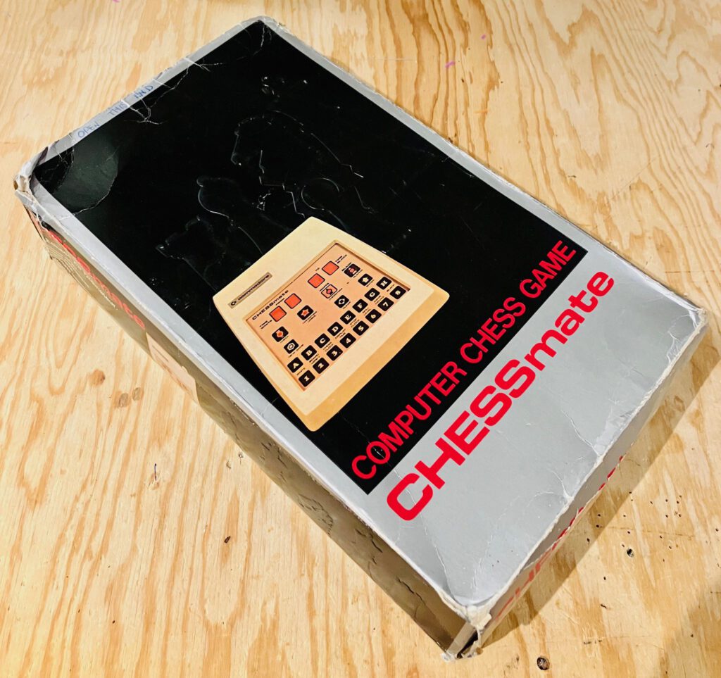
Photo by Michael Gardi
Novag Chess Champion MK II A and B
TEC Schachcomputer


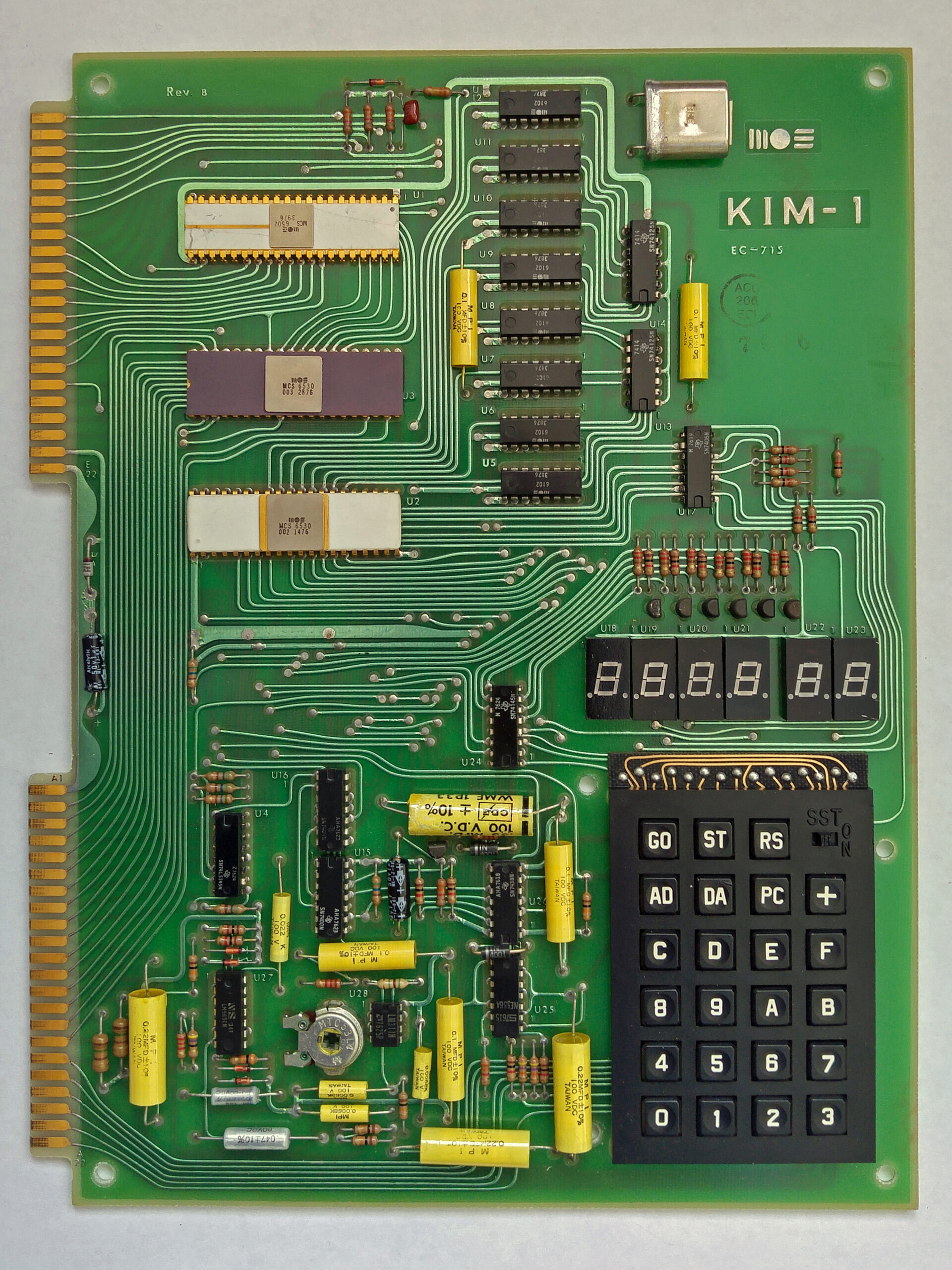
 The KIM-1 debuted during Wescon in Chuck Peddle’s hotel suite, along with the 6502 and other development systems. Users received the small computer enthusiastically. Al Charpentier recalls, “They sold a lot of those. It was sort of the first fully packaged microcomputer that you could take out of the box, throw a power supply on, and do something with. It was hell, but it educated people on the processor.”
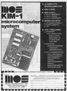
 Another early programmer who would gain recognition in the industry was Jim Butterfield. For Butterfield, using a KIM-1 was an adventure in exploration. His goal was to uncover the hidden secrets of the KIM-1 and pass that knowledge on to other users. Jim has the rare ability to understand complex subjects and describe them in simple terms. One of the biggest barriers to learning about microcomputers in those days was the problem of communicating knowledge since the average hacker seemed to be speaking a different language. Butterfield allowed those on the outside to enter the world of programming in comfort.