This page is a Work in Progress since November 2022!
The clones of the KIM-1 that appeared the last years have renewed the interest of the retro scene.
Old software is restored or typed in again and adapted to the current use of serial terminal emulators and cross assemblers instead of the hardcopy Teletype interface and native assemblers of the old days.
This site contains a lot of that material already. There I have tried to collect all older original material.
Here a link of current websites with relevant material. As usual, a list of external links always will suffer of bitrot, so please report dead links!
Netzherpes, by Nills. Very active PAL-1 user. Lots of older software newly typed in.
- Blog
- Sources and binaries
- Youtube movies
- Very large archive, kept uptodate, with KIM-1/PAL-1/6502 resources
KIM IEC, Dave McMurtrie’s 1541 Routines for the KIM-1
- Youtube on KIM IEC
- See also the site of Netzherpes for circuit diagram and a trick to use this form KB9 Microsoft Basic
See also the Nachbau KIM-1 IEC/RAM card page.
SD card on PAL-1 https://github.com/ryaneroth/sdcard6502
https://www.youtube.com/@masterhit1/videos masterhit Nils
https://www.youtube.com/watch?v=CovNzC3jdGo KIM Venture
https://www.youtube.com/watch?v=d88M8gFSzWE startrek
https://github.com/w4jbm Jim McClahanan
https://www.youtube.com/@W4JBM/videos https://www.youtube.com/watch?v=UThleUTNTBM
PAL- stores/tkoak/
https://www.tindie.com/stores/tkoak/
http://pal.aibs.ws/support
Debug packages
1541
Lilbug
Basic games
Tiny Basic
TINY BASIC program test on PAL-1 (in German, which I don't understand 😱, just copied from the Tiny Basic Handbuch) #KIM1 #PAL1 #MOS6502 @JohnKennedyEsq pic.twitter.com/yMLbjz9xU3
— Liu (@LiuGN) October 9, 2022
https://github.com/GrantMeStrength/KIM1
Jim
https://github.com/w4jbm/PAL-1-6502-SBC
KIM-1 Computing Focal etc
PAL-1 Hacks
https://github.com/kaveenr/PAL-1-HACKS
https://netzherpes.de/
https://github.com/netzherpes
https://www.youtube.com/user/masterhit1
https://drive.google.com/drive/folders/1-S3AI-qszLDSes50MERtx1RNl9KefTs7
KIM IEC
https://commodore.international/kim-iec/
CC65 pathches
https://github.com/davepl/cc65
Jeff Tranter
https://github.com/jefftranter/6502/tree/master/asm/KIM-1
Discussion forum for PAL-1
https://groups.google.com/g/pal6502
twitter friends
@LiuGN PAL-1 desigenr/tindie
@masterhit netzherpes
@Devilish_Design (KIM-1 clone)
MOS KIM-1 Reproduction Kit https://www.ebay.co.uk/itm/225209469024
http://www.corshamtech.com/product-category/kim-1-products/
Bob Applegate Corsham Technologies
https://github.com/CorshamTech
http://www.corshamtech.com/product-category/kim-1-products/
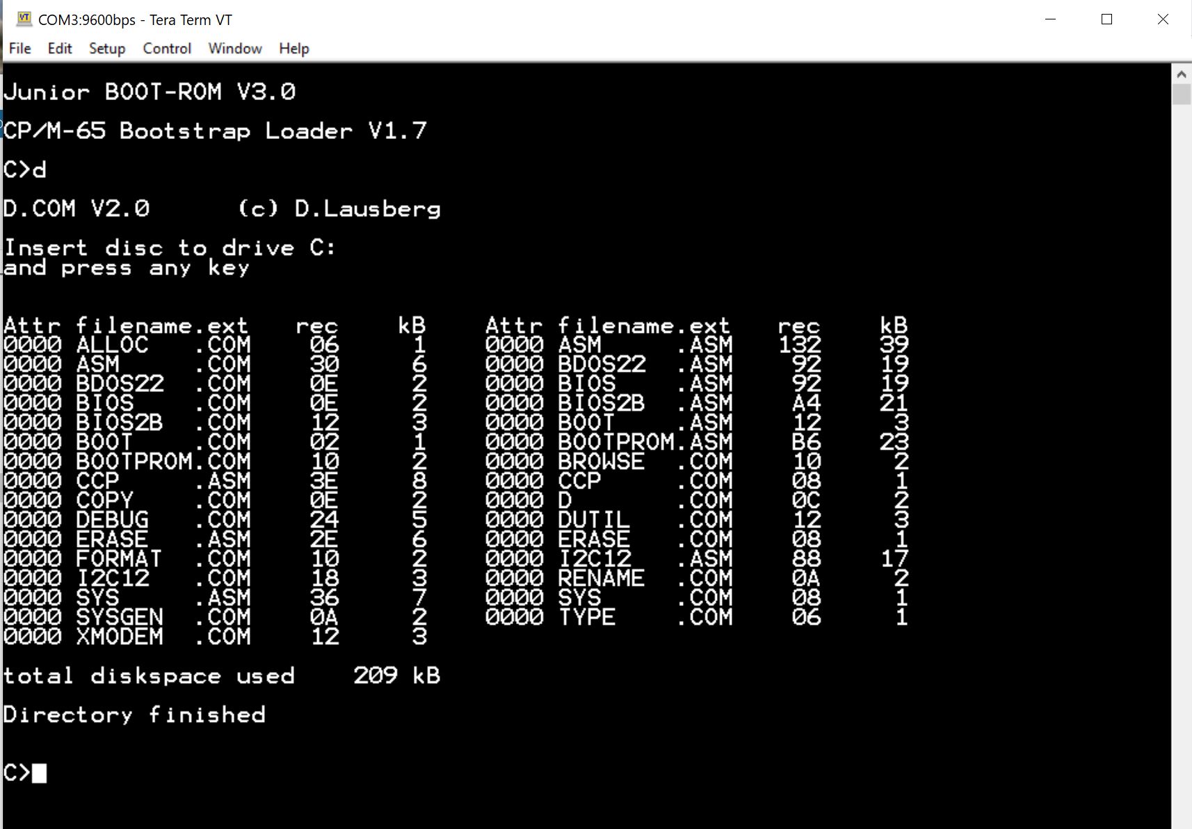


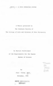
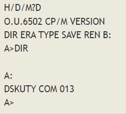 A thesis by Jian – Xiong Shao, 1983, titled OUP/M – A 6502 Operating system, contains a floppy disk based operating system for the 6502. It is modelled after CP/M and follows the same design principles.