Some tips that I learned programming for the KIM-1 and the 6502.
ALWAYS CHECK YOU DO NOT FORGET IMMEDIATE ACCESS SYNTAX!
It so easy an common to forget the ‘#’ in your assembler code. Assemblers will not complain and make it absolute or zeropage addressing and you will search for hours!
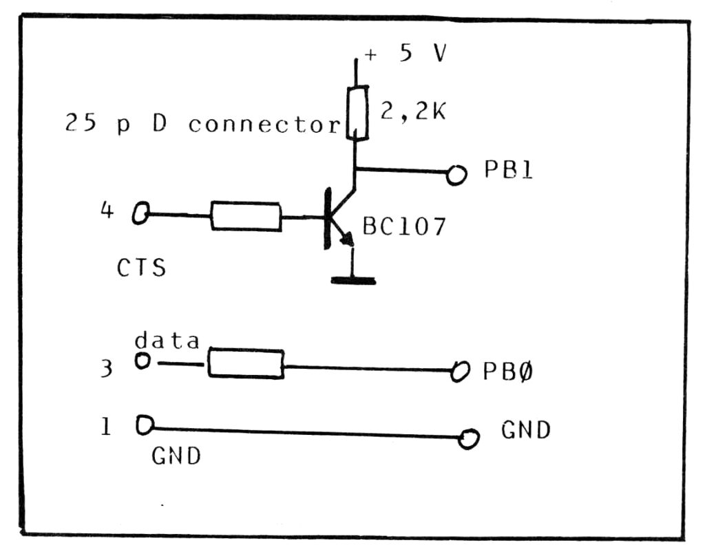
TTY routines
Do not use the CRLF routine at $1E2F in the monitor
This routine sends the CR and LF to the TTY output vai OUTCH. Nice, you will need that often in a console program.
But if you read the page on printing a string you see this routine also sends out 6 Null ($00) characters, this takes a lot of wasted time!
Just make your own subroutine
LDA #$0D ; CR
JSR OUTCH
LDA #$0A ; LF
JSR OUTCH
RTS
Note that this destroys A and Y!
GETCH gets a character to serial TTY.
Blocking, it waits indefinitely for a character to arrive and A will have the value.
The routine also kills the Y register, returns with Y = $FF.
Also, in LED Display and Keyboard mode, it returns with A = $01 and X = 8.
Save Y before calling GETCH, and restore Y when it returns.
OUTCH sends a character to serial TTY
No handshaking, no hardware flow control, it just spits out the character.
A destroyed, Y=FF, X preserved.
Save at least Y, and saving A is recommended.
SPACE print a blank
This just calls OUTCH with A = $20, so read OUTCH for the side effects.
PRTBYT Print A as two hex characters
Uses OUTCH, so Y is lost. A is preserved.
GETBYT and GETBYTC
X saved, Y = 0, A is hex character
Reads two hex characters (0..9 A..F) and tries to pack them in A.
See the page on PRTBYT,GETBYT and PACK for an error checking alternative GETBYTC to GETBYT.
Note that due to an incomplete check ‘:’– ‘?’, $3A .. $3F are accepted as valid hex characters A ..F.
KIM
0200 A9 ;;
00BB 00 ::
00AA 00 ????
FFFF 1C
The audio tape routines
The DUMPT and LOADT routines are OK to call interactively to dump and load KIM-1 files on tape.
The cannot be called as subroutines. when finished they return to the KIM-1 monitor.
DUMPT return with $0000 as current address pointer in the KIM-1 monitor.
LOADT returns it status via the current address pointer in the KIM-1 monitor, $0000 is success, $FFFF is a loading error.
What you can do is:
– Have code at $0000 to return to your program (Warm start entry), so the user just has to press G
– instruct the user what to do if DUMPT returns $FFFF
The better solution is to incorporate Hypertape as callable subroutine.
Return to the KIM-1 monitor
The preferred location to call to enter the KIM-1 monitor form a user program is START at $1C4F
Reading the keyboard and lighting the display
Fill F9, FA, FB with the values to show on the LED displays
Call SCAND
Call SCAND to debounce
CaLl GETKEY
Now check the key in A:
– above $14 : no key
– 14 = PC
– 13 = GO
– 12 = +
– 11 = DA
– 10 = AD
– 0 ..9 A – F keys
Handle key and loop back to the begin