A Christmas Story About A Tiny TIM
By Joseph Watson
I am a retired software engineer. I still program microcontrollers for fun. These days I concentrate on Microchip’s PIC chips, especially the PIC18 series chips. I retired from professional work at the end of 2010 and this year, 2016, I will turn 71 years old toward the end of the year.
Many years ago in 1971 at the ripe old age of 25, I bought a used DEC PDP-8/s minicomputer and played with it for many an hour. I even made a bit of extra money on the side by writing programs for that machine. (Yes, I still have the PDP-8/s.)
Early in 1975, a friend of mine bought a MITS Altair 8800 kit and invited me to help him build it. I was glad to help. That computer uses an Intel 8080 CPU chip. We soon had that machine blinking its lights and making strange noises in a nearby radio, but the fun seemed pretty limited for a little while.
Then a couple of college students named Bill Gates and Paul Allen wrote a BASIC interpreter for the Altair computer using the hitherto unknown company name of MicroSoft. My friend laid out the cash for the 4-kilobyte version of that product and we were soon writing BASIC programs for fun. Then my friend added an additional 4 kilobytes of RAM to his Altair and bought the 8-kilobyte version of MicroSoft BASIC. We spent many pleasant evenings in his basement writing BASIC programs for his machine. (By the way, my friend still has his Altair computer.)
In the era of the mid-1970s, microprocessor chips were still quite new but were becoming more known. The question on every would-be computer hobbyist’s lips was the same, “Which microprocessor chip is better, the Intel 8080 or the Motorola 6800?” I drooled over such things but, at more than a hundred dollars each, the cost surely seemed high for just a single silicon chip.
As I recall, some 8 guys who had been involved in the Motorola 6800 development left that company and joined MOS Technology, a calculator chip manufacturer, where about September of 1975 they created the very clever and much less expensive (about $25) MOS Technology 6502 CPU chip. Needless to say, my drooling intensified.
My TIM system got its start when my wife gave me, as a 1975 Christmas gift, just what I wanted most, a brand new MOS Technology 6502 microprocessor chip, a 6530-004 TIM chip, and 8 2102 static RAM chips. A 2102 RAM chip stores a whopping 1024 bits, organized as 1024 x 1. Those RAM chips ran so hot that you could not begin to touch them when they were operating.
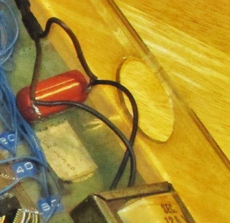
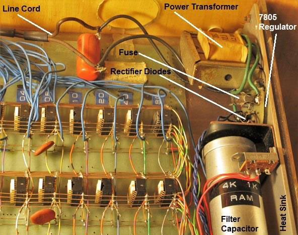
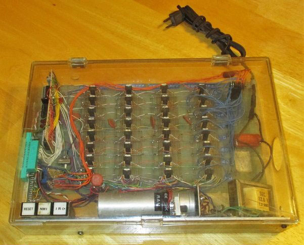
I had a clear plastic box that I thought would make a nice enclosure for my TIM project. I took a large old printed circuit board and carefully stripped all the old parts and traces off of it to create a solid surface upon which to mount most of my circuitry, sort of a fiberglass chassis. I built up a simple 5-volt power supply to power the system consisting of a 120VAC to 12.6VAC transformer, a fuse, 4 1N2071 diodes wired as a full-wave bridge rectifier, a 2000 MFD 40 VDC filter capacitor, and a 7805 5-volt regulator. A long piece of aluminum running the length of the front side of the plastic box serves as the heat sink for the reguator. See Fig 1.
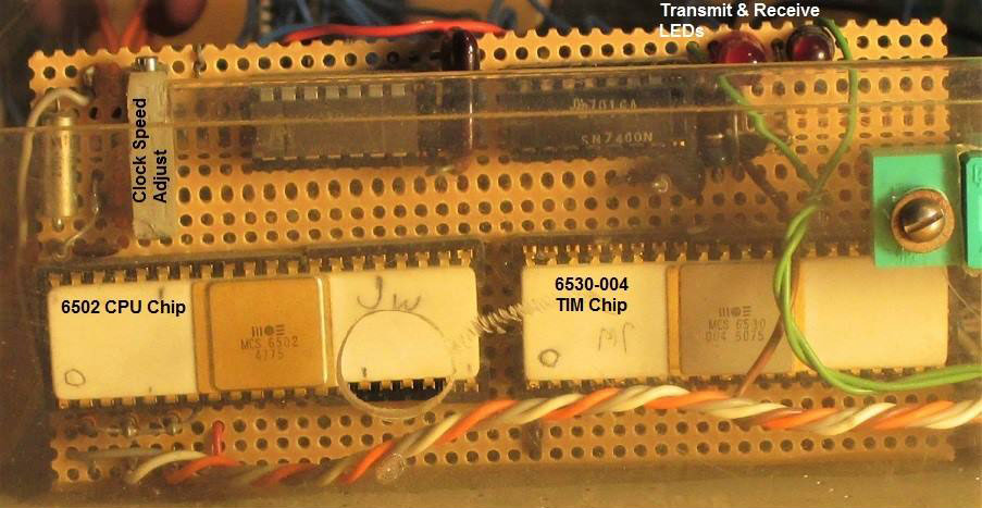
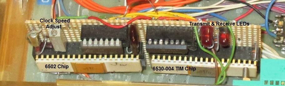
The CPU and the TIM chips were installed on a small perf board that was then glued with epoxy cement standing on edge on the large board inside the box. Additional components on this CPU/TIM board include a couple of 7400 quad 2-input NAND gate chips that I scraped up, about 9 resistors, a few small capacitors, and a couple of transistors that were involved in transmitting and receiving the 20-milliamp current loop signals for the Teletype. See Figs 2 and 3.
The 6502 supports several methods of being clocked. One uses a very simple external RC circuit so I chose that one. I included a potentiometer in the RC circuit so I could adjust the clock speed if needed. Since the TIM uses an autobaud feature to determine the timing for the serial interfaces, the clock speed needed only to be relatively constant but not any particular speed. See Figs 2 and 3.
I included a couple of red LEDs on the CPU/TIM board to reveal the state in the interface current loops with the Teletype, one for the sending side and one for the receiving side. (By the way, when I built this, we only had red colored LEDs. I had seen my very first LED in 1971, just 5 years earlier.) See Figs 2 and 3.
Aside from the CPU, TIM chip, and the RAM chips, most of the parts in this machine were salvaged parts scrounged from other old equipment and my spare parts box. The power transformer came from a nearby Radio Shack store. The IC sockets were wire wrap sockets that I unwrapped from old prototype boards being thrown out where I worked. However, I had no wire wrap tool so everything in the TIM system was soldered point-to-point.
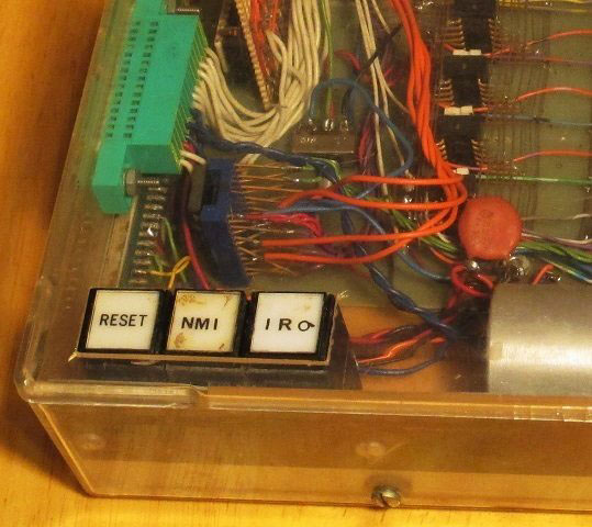
Three push buttons were installed through the top of the plastic box for Reset, NMI, and IRQ. For the most part, only the Reset button was ever used. I may have used IRQ a few times. See Fig 4.
I made a little fan to keep the whole thing cool. The fan consisted of a small DC motor with a homemade aluminum fan blade on it. Eventually, I determined that the fan was just way to small for the amount of heat generated in this plastic box so I removed the fan and started using an external fan to cool it. All that remains of the old fan idea is the hole where it used to be located. See Fig 5.
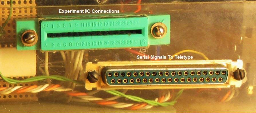
As with many TIM systems, mine was connected to an ASR-33 Teletype unit. (Yes, I still have the Teletype, too.) Therefore, 10 bytes per second was the blazing speed for printing and for loading a program via 8-channel punched paper tape. I brought the serial lines out to a 37-pin connector on the side of the box. (Only slight overkill there… a 37-pin connector with only 4 electrical connections needed. One never knows when one will find a need for 33 spare pins.) See Fig 6.
I brought all the spare I/O port lines out to a connector on the side of the plastic enclosure so I could easily attach experimental interface circuitry there. See Fig 6.
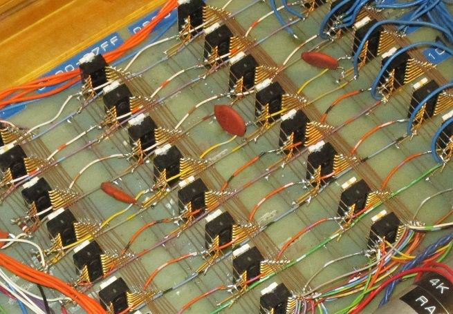
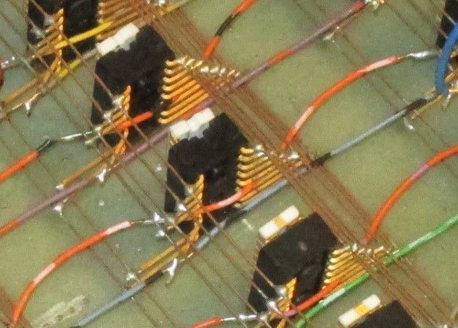
To maximize cooling for the blistering hot RAM chips, I stood them on end, hoping for a degree of chimney effect cooling. They were all mounted in sockets as were all the chips of the project. Right from the beginning, I allowed room for an additional 24 2102 RAM chips so the system could grow from 1 kilobyte to 4 kilobytes of RAM. Standing the RAM chips on end resulted in one of the oddest physical wiring tricks in anybody’s computer and which is, no doubt, evident in the photos. Notice that much of the RAM array wiring was done with bare wire. For most of the wire in this project and especially the RAM array wiring, I used telephone wire which is to this day, one of my favorite kinds of hookup wire when solid wire is the best choice. It was easily stripped to make the bare wires for the RAM array. See Figs 7 and 8.
Aside from the ICs being in their sockets and a few connectors to the outside world, virtually every interconnection in this machine is hard wired with no connectors. It is obvious to me by looking at it now that I built the CPU/TIM board and then glued it down expecting to never have to change anything on it. (I do see that I tacked a capacitor onto the back of it at some point.) Looking at it now, I am surprised by some of the construction methods I used at that early time in my life (I was 30 years old). We all learn a lot as we grow older.
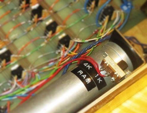
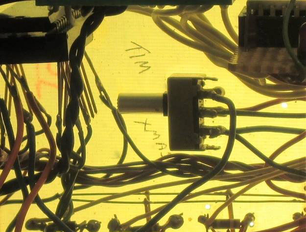
One kilobyte is a pretty small memory in which to store one’s program so I soon added the 24 additional 2102 RAM chips resulting in a total of 4 kilobytes of RAM. But that also made the little computer run really hot as well. So I added a slide switch to the system to choose whether it should run with 1 kilobyte or 4 kilobytes of RAM. That switch simply turns the power on or off to the extra RAM chips, thereby sometimes making life easier on the poor 7805 that was struggling to supply power to all those hot chips. See Fig 9.
There is a 74154 4-line to 16-line decoder that is involved in address decoding for the RAM chips (and for the EPROM chip described below). See Fig 10.
One reason for extending the RAM was that I found out about the existence of Tom Pittman’s Tiny Basic for the 6502 which cost a very reasonable $5 at the time. I loaded that little integer BASIC system and played with it often. Tom’s implementation is very compact and much could be accomplished even in a mere 4 kilobytes.
I wrote a number of assembly language programs as well. Clearly, the best one I ever wrote was a program to control a large set of Christmas lights that I strung across the front of my house. Each evening while I was on my way home from work, my wife would place a carefully prepared paper tape into the Teletype reader, turn on the power to the entire system, press the system Reset button, and turn on the Teletype reader. The tape contained a Carriage Return character to allow the TIM to determine the baud rate. After that came a TIM command telling it to load. Then came the machine code for the Christmas light program. When loading completed, one final TIM command on the tape started the program to running and the Christmas lights did their thing. It was always fun to arrive home and see my Christmas lights doing their dance before I even arrived. I used this little computer to run my Christmas lights so many times that it became clear that it would be smart to store the Christmas light program in an EPROM chip instead of loading it every evening from a paper tape. So I then added another slide switch inside the machine to optionally disable the TIM chip and enable a 2716 EPROM (2 kilobytes) plus a 7420 dual 4-input NAND gate chip (probably for address decoding) tucked into a corner of the box. When switched to the Christmas light position, one only had to power up the computer and press the Reset button to get the lights to go. By the way, there is no power switch other than plugging in or pulling out the power cord. See Figs 11 and 12.
The 7400 series chips are plastic and one 2102 chip is plastic. (I think I had to replace one of the original 2102 chips later because it had a habit of dropping bits, hence the plastic one.) Every other chip, including the 6502 and the 6530-004 TIM chip, are ceramic chips.
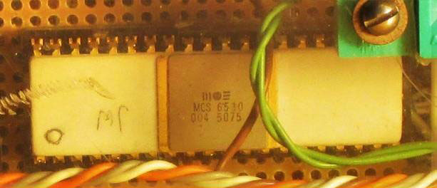
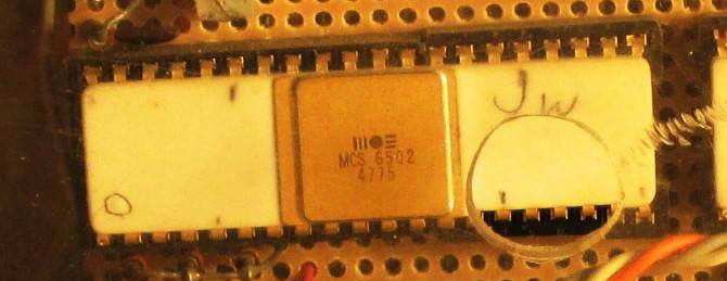
Looking over this little system after all these years, I have rediscovered many things about it that I had forgotten, most of which I have mentioned above. There is one more thing that I find of interest and that is the date codes. The 6502 CPU chip has a date code of 4775 meaning it was manufactured just about 4 weeks before I received it for Christmas. The 6530-004 TIM chip has a date code of 5075 meaning it must have still been a little bit warm when I got it as it had been made a mere week or so before it found its way under my Christmas tree. See Figs 13 and 14.
For those in the know, one might ask if my 6502 CPU chip includes the ROR (Rotate Right) instruction. Frankly, I can no longer remember if it does or not. I do remember the discussions about the issue of the earliest 6502 chips not having it.