Instant Pascal manual
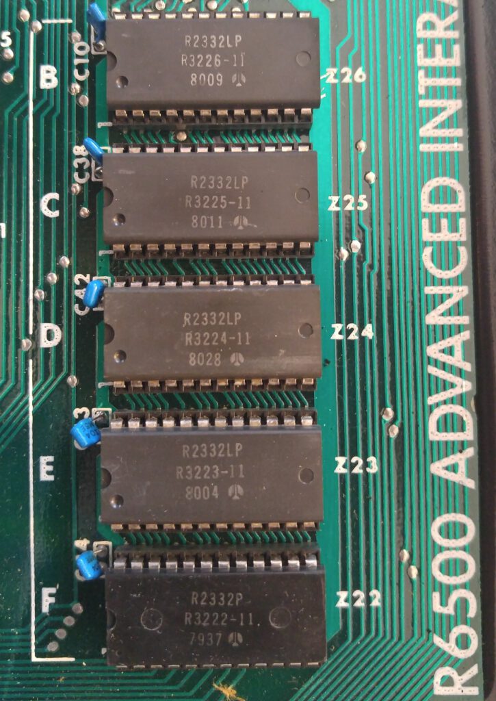
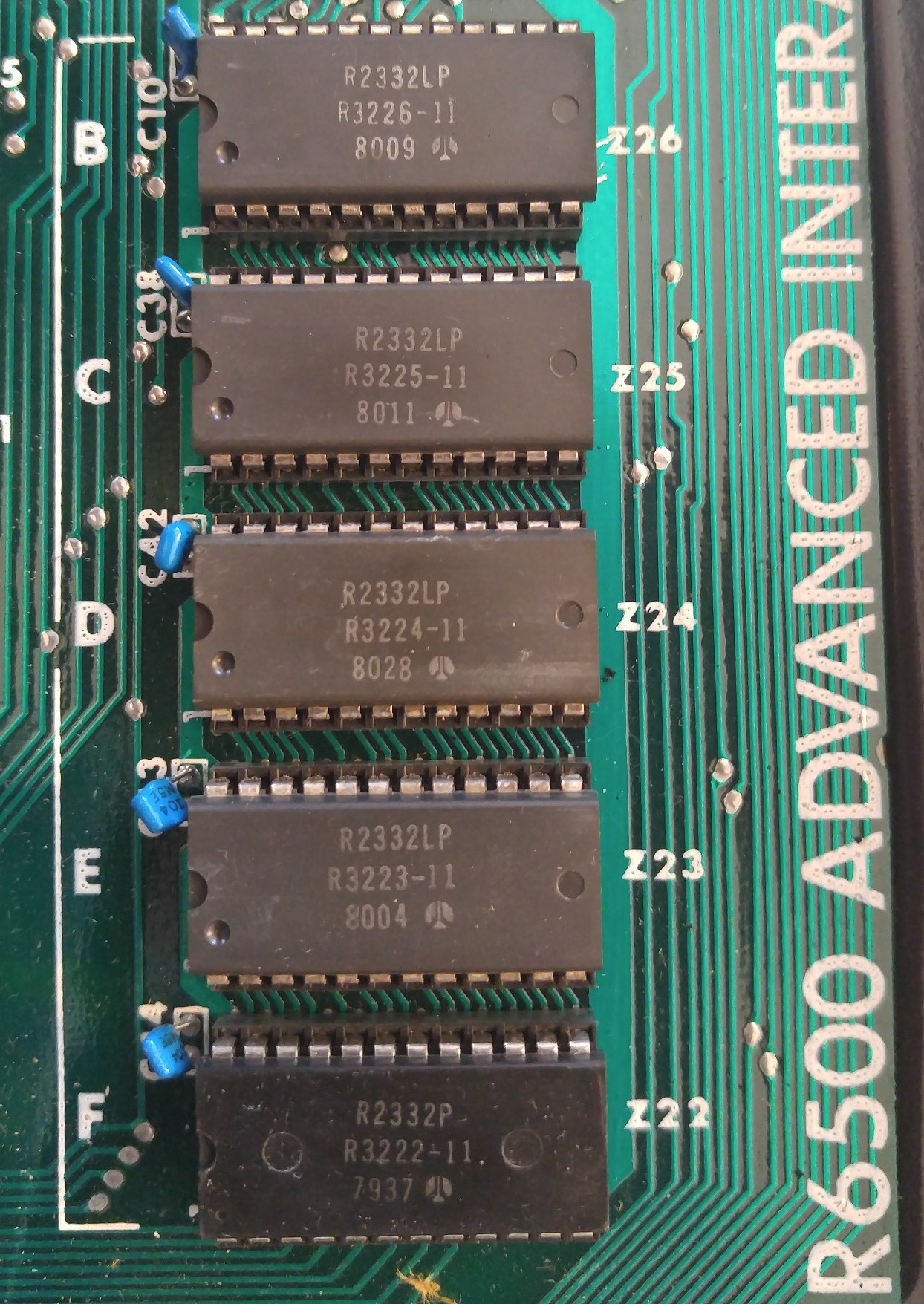
ROM R32P2
ROM R32P3
ROM R32P4
ROM R32P5
ROM R32P6
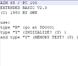
Instant Pascal, an interactive Pascal variant “INSTANT PASCAL(TM) (C)1981 MELVIN E. CONWAY”
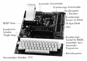
5 ROMS, available in hex format. See the manual how to install, it needs an external expansion adapter, see the Other hardware page
Background of Instant Pascal
By Mel Conway http://heed.melconway.com/HEED/History.html
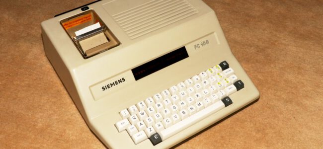
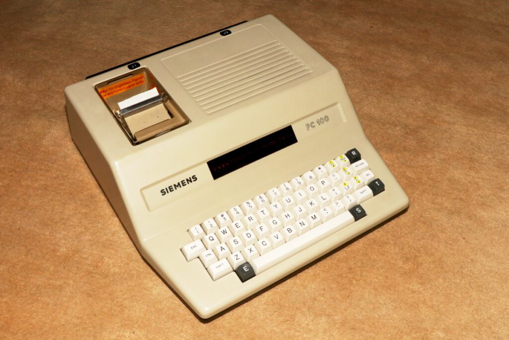
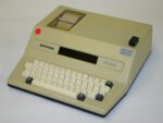
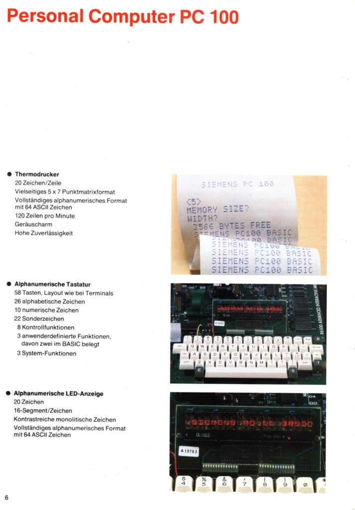
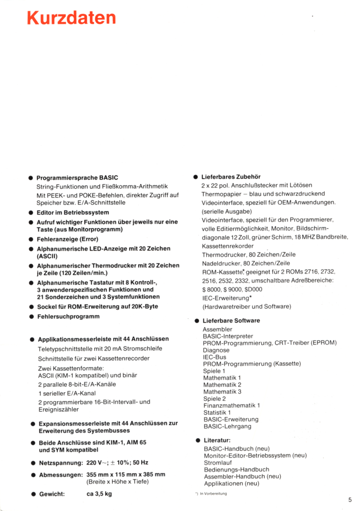
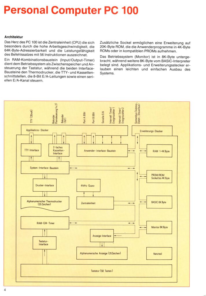
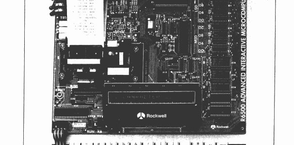
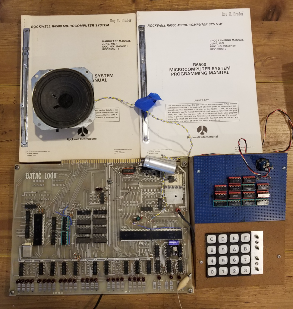
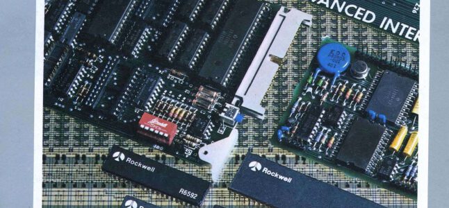
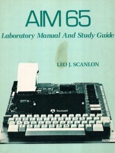
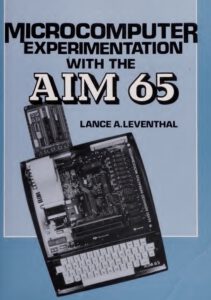
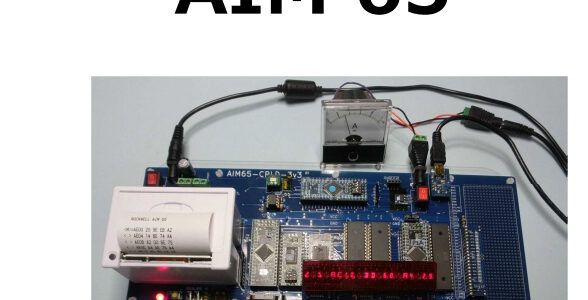
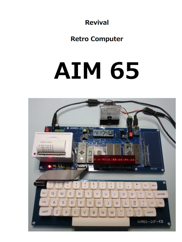
I proposed to Rockwell to build an “Instant Pascal” trainer to run on the AIM-65, and the proposal was accepted. The AIM-65 was a single-board computer with an 8-bit Rockwell 6502 (the processor used in the Apple II), 4K bytes (that’s right, 4096 bytes) of internal “random-access” memory (RAM), up to 20K bytes of on-board “read-only” memory (ROM), and various byte-at-a-time input-output possibilities. The user interface consisted of a teletype-like keyboard, a single-line 20-position LED alphanumeric display, and a thermal strip printer with 20 characters per line. (The only widely used external storage was an audio cassette recorder.) The intention was that the user would get Instant Pascal in the form of a set of ROMs. You plug these ROMs into the AIM-65 and you have a Pascal trainer.
The AIM-65 had multiple hardware limitations. The major one, of course, was the 4K RAM. But the single-line display wasn’t helpful. Clearly, any Pascal editor would have to be a “line” editor, not a “screen” editor. The traditional solution would have been to prepare a program in four steps: (1) the entry step, in which you prepare a source tape; (2) the edit step, in which you modify your source program by doing tape-to-tape copies under control of the keyboard and display; (3) the compile step, in which you read a source tape and write an object tape; and (4) the run step, in which you load the object tape and execute it. Debugging is clearly a problem because you have to have both the source program in view (so you can find and fix your mistakes) and the object program in memory (so the program can run). How can you do that in 4K of memory? And how are you going to do all four (or five, if there is a separate debugger) steps under control of 20K of ROM? I had no intention of building a language trainer that way.
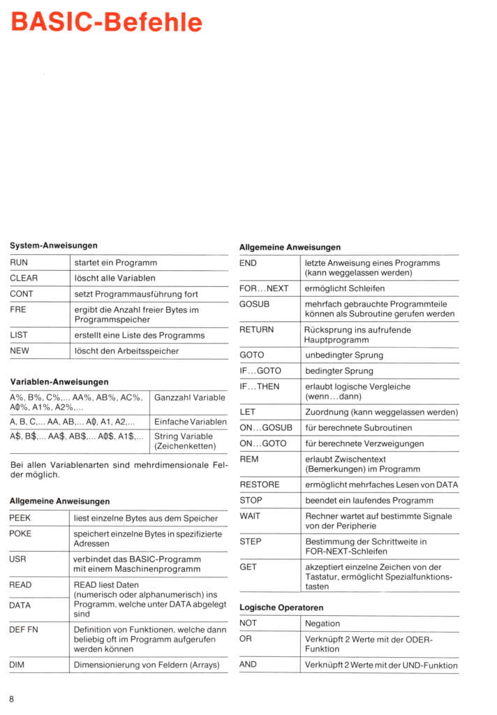
There was an alternative: to store the Pascal source code in the 4K RAM and interpret it directly. Waterloo Pascal1 did that. They had the right idea, but directly interpreting source code made it really slow compared to BASIC, which was the alternative at the time. I was, frankly, relieved to discover how slow Waterloo Pascal was, because I already had the outline of another approach.
The Approach
As with Waterloo Pascal, my solution to eliminating the build-run dissonance was a single internal representation of the program that stayed in RAM. It had to be compact, efficiently interpretable, and readily translatable back to Pascal source so that no source program needed to be stored. The approach I took is today called a “tokenized” representation of the Pascal program. The internal representation of the Pascal program was syntactically correct Pascal: I specified the token language using the formal Pascal syntax. This assured syntactic similarity between external and internal representations of a program. I put one constraint on the user: text had to be entered in “prettyprint” form (no indenting necessary), one line per prettyprint line. Fortunately, this was not a source of complaint, because entering code this way was considered to be good practice; thus this most serious limitation was reframed as a feature. The prettyprint input constraint permitted line-by-line translation into token form (and local syntax checking, with immediate feedback), and there was no need to store more than one line of Pascal text internally.
The parts of the program consisted of (1) a single-line source-code tokenizer/syntax checker (“forward translator” from keyboard to RAM); (2) its reverse, a single-line token-to-source “backward translator” from RAM to printer; and (3) a token interpreter that executed the program. There was a fourth component, a “binder,” that scanned the tokenized program after you entered the “run” command, and established (and checked) those syntactic connections that spanned multiple lines. The binder had very little to do, and its execution time was typically imperceptible. Source-code debugging fell out of this design: any line being executed by the interpreter can at the same time be output as Pascal source by the backward translator. During debugging the system could appear to execute at the source level, stop on lines with breakpoints, and evaluate source-level “watch” expressions.
The Lesson
The result of this design was the illusion of executing Pascal source language, but at the speeds of typical BASIC programs. In fact, maintaining the illusion of a single program representation became the principal user-interface design goal. It is this illusion of always dealing with your program at the source-code level that resolves the build/run dissonance and that obviates the need for a separate debugger.
The design was successful and next found itself inside Macintosh Pascal in 1984. But the resolution of the dissonance wasn’t complete. Instant Pascal was a trainer, not a construction tool. As compiler writers know, you don’t have a real production tool until you can build the tool using itself, and this could not be done.