
This is the GETCH routine to read a character for the serial TTY input.
Note that the routine is blocking (waits for the character), returns with the received character in A and makes Y FF.
That clobbering of Y creates often problems in calling programs, so save/restore Y also with GETCH.
0935   1E5A             ;
0936   1E5A             ;       GET 1 CHAR FROM TTY
0937   1E5A             ;       CHAR IN A
0938   1E5A             ;       X IS PRESERVED AND Y RETURNED = FF
0939   1E5A             ;
0940   1E5A 86 FD       GETCH   STX   TMPX        ; SAVE X REG
0941   1E5C A2 08               LDX   #$08        ; SET UP 8-BIT COUNT
0942   1E5E A9 01               LDA   #$01
0943   1E60 2C 40 17    GET1    BIT   SAD
0944   1E63 D0 22               BNE   GET6
0945   1E65 30 F9               BMI   GET1        ; WAIT OR START BIT
0946   1E67 20 D4 1E            JSR   DELAY       ; DELAY 1 BIT
0947   1E6A 20 EB 1E    GET5    JSR   DEHALF      ; DELAY 1/2 BIT TIME
0948   1E6D AD 40 17    GET2    LDA   SAD         ; GET 8 BITS
0949   1E70 29 80               AND   #$80        ; MASK OFF LOW ORDER BITS
0950   1E72 46 FE               LSR   CHAR	  ; SHIFT RIGHT CHAR
0951   1E74 05 FE               ORA   CHAR
0952   1E76 85 FE               STA   CHAR
0953   1E78 20 D4 1E            JSR   DELAY 	  ; DELAY 1 BIT TIME
0954   1E7B CA                  DEX
0955   1E7C D0 EF               BNE   GET2        ; GET NEXT CHAR
0956   1E7E 20 EB 1E            JSR   DEHALF      ; EXIT THIS RTN
0957   1E81             ;
0958   1E81 A6 FD               LDX   TMPX
0959   1E83 A5 FE               LDA   CHAR
0960   1E85 2A                  ROL   A           ; SHIFT OFF PARITY
0961   1E86 4A                  LSR   A
0962   1E87 60          GET6    RTS
What is happening here?
- save X and use as 8 bit data counter (94-941)
- exit if not TTY (942-944, 962)
- wait for PB7 to change to startbit (943-945)
- delay 1 bit time, let the startbit end (946)
- delay 1/2 bit time, so we are in the middle of the data bit (947
- shift databit at PA7 into character received (948-952)
- delay 1 bit time (953)
- repeat until 8 dat bits (954-955)
- delay 1/2 bit time
- shift off most significant bit, leave 7 databits (959-962)
This is a simple bit banging routine to get a character from serial input.
It assumes the serial input at rest: starting listening at input when there is no activity on the input, and then triggers when the startbit appears.
It waits 1,5 of the (measured) bit time, and then clocks in 8 databits. Essential is that the bit value is determined in the middle of the data bit coming in.
Only seven bits are preserved, the last bit (called parity here) is shifted off. Quite robust and also quite tolerant for small speed variations.
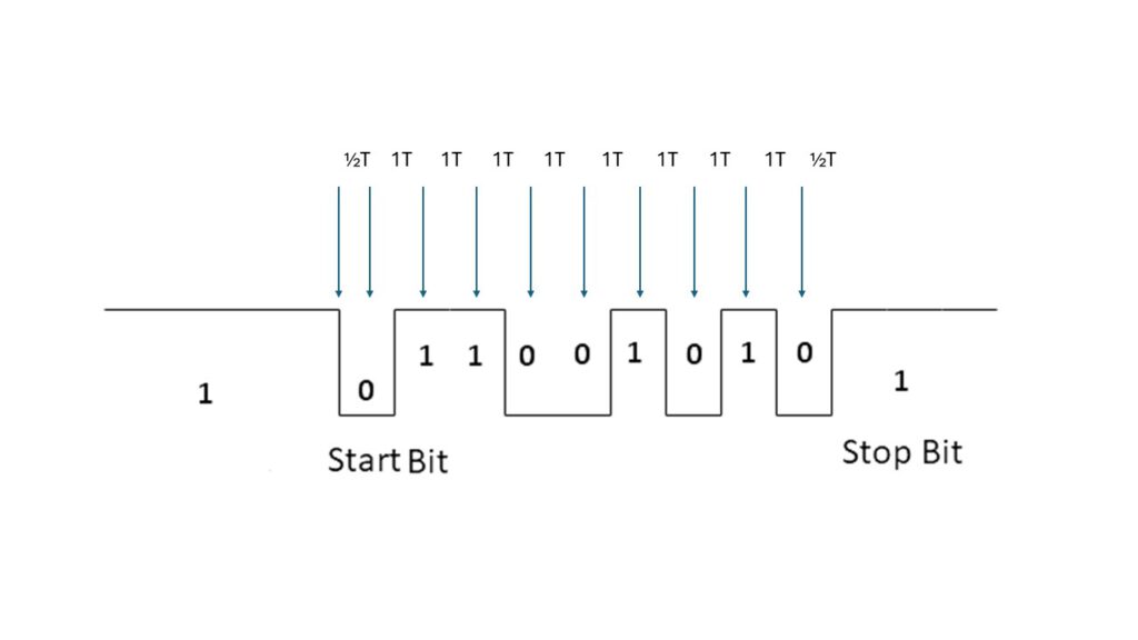
Some remarks here:
- GETCH reads 8 databits and discards the last bit read (with the ROL /LSR). So you can read only 7 bit characters.
- Parity, one or two stopbits, it does not matter, they are ignored. Only the seven databits matter, a parity bit is ignored by shifting it off.
-
The check for a startbit is is as to be expected:
0942 1E5E A9 01 LDA #$01 0943 1E60 2C 40 17 GET1 BIT SAD 0944 1E63 D0 22 BNE GET6 .. 0962 1E87 60 GET6 RTS -
There is a remarkable instruction sequence here. After the BIT a BNE jumps the RTS, so GETCH returns with A 01.
This can only happen when GETCH is called with the TTY switch off. The serial line is checked in bit 7 if port A, PA7 with the BMI loop.This is even used in
0648   1C6A 20 5A 1E    READ    JSR   GETCH      ; GET CHAR
0649   1C6D C9 01               CMP   #$01
0650   1C6F F0 06               BEQ   TTYKB
So calling GETCH in LED display/Keyboard mode does not work!
How fast a baudrate can GETCH work with?
1006   1ED4             ;
1007   1ED4             ;       DELAY 1 BIT TIME
1008   1ED4             ;       AS DETERMINED BY DETCPS
1009   1ED4             ;
1010   1ED4 AD F3 17    DELAY   LDA   CNTH30     ; THIS LOOP SIMULATES
1011   1ED7 8D F4 17            STA   TIMH       ; DETCPS SECTIONS AND WILL DELAY
1012   1EDA AD F2 17            LDA   CNTL30     ; 1 BIT TIME
1013   1EDD 38          DE2     SEC
1014   1EDE E9 01       DE4     SBC   #$01
1015   1EE0 B0 03               BCS   DE3
1016   1EE2 CE F4 17            DEC   TIMH
1017   1EE5 AC F4 17    DE3     LDY   TIMH
1018   1EE8 10 F3               BPL   DE2
1019   1EEA 60                  RTS
1020   1EEB             ;
1021   1EEB             ;                          DELAY 1/2 BIT TIME
1022   1EEB AD F3 17    DEHALF  LDA   CNTH30     ; DOUBLE RIGHT SHIFT OF DELAY
1023   1EEE 8D F4 17            STA   TIMH       ; CONSTANT FOR A DIVE 2
1024   1EF1 AD F2 17            LDA   CNTL30
1025   1EF4 4A                  LSR   A
1026   1EF5 4E F4 17            LSR   TIMH
1027   1EF8 90 E3               BCC   DE2
1028   1EFA 09 80               ORA   #$80
1029   1EFC B0 E0               BCS   DE4
The monitor subroutine DELAY (starting address 1ED4) counts down from the value in memory locations 17F2 and 17F3 (MSBs in 17F3). It uses memory location 17F4 for temporary
storage.
The total time required by DELAY is (in clock cycles):
- 24 for a JSR (6), RTS (6), and the initial loading of the accumulator and memory location 17F4 (the first three instructions, each of which takes four cycles).
- 14 for each iteration that does not decrement memory location 17F4 (i.e., no borrow from the more significant byte). This path is made up of SEC (2), SBC #$01 (2), BCS involving a branch (3), LDY $17F4 (4), and BPL involving a branch (3).
- 19 for each iteration that decrements memory location 17F4. This path differs from the previous path by including DEC $17F4 (6) and eliminating the branch from BCS (—1). The
- final (exiting) iteration takes one cycle less since BPL does not cause a branch.