![]() |
SS-30 Parallel Board Manual |


About small SBC systems
![]() |
SS-30 Parallel Board Manual |


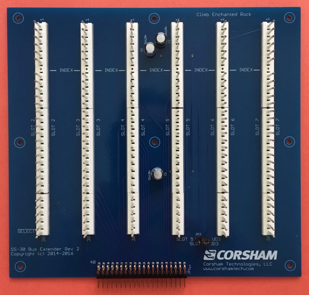
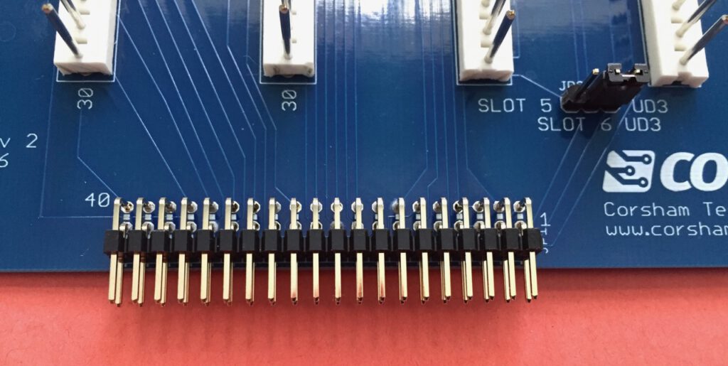
For those of you using one of our SS-50 motherboards and find yourself needing more I/O ports, this board will add an additional six SS–30 ports via a connector already on your motherboard. This extender simply plugs in and you’ll have the full eight slots available for more I/O boards. As you can deduce from this picture, each slot has a fixed address unlike the two slots present on the motherboard:


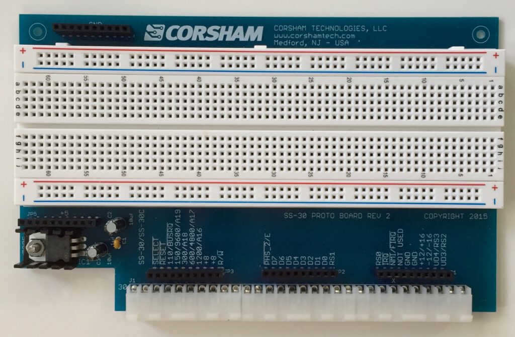
Two versions were produced of the SS-30 Prototype board, small and large.


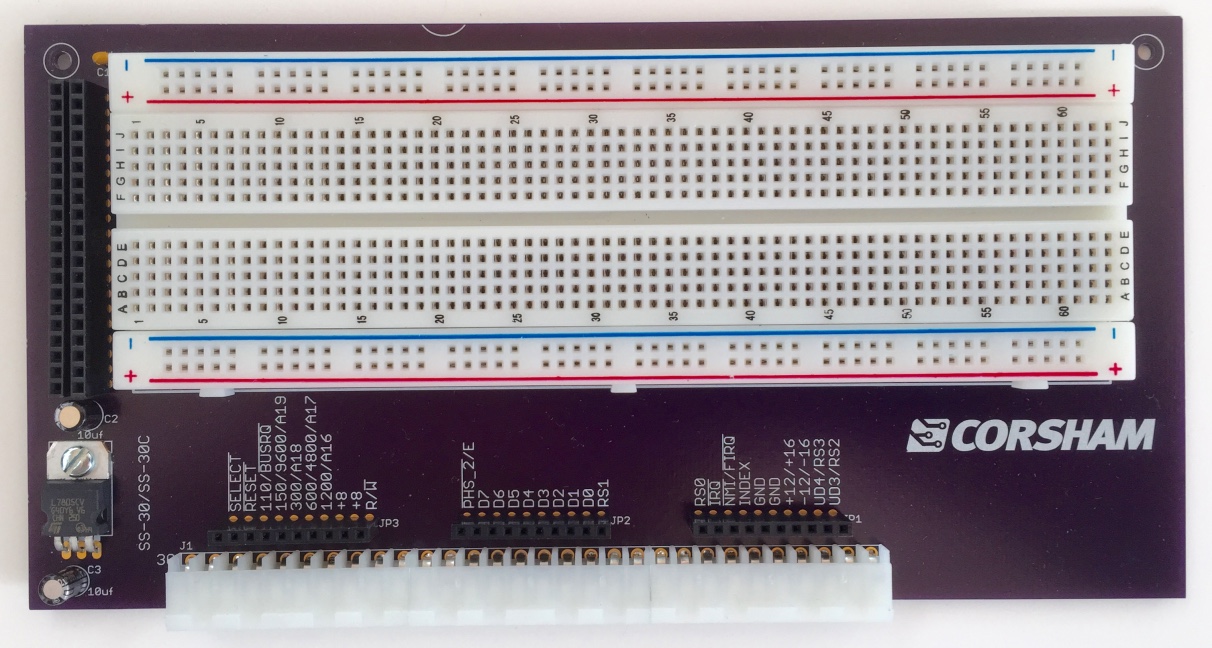
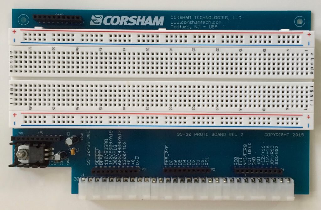
Yet another experiment that we needed to develop our own products. This is meant to allow someone to experiment with building their own SS-30 (I/O) boards. The two connectors on the left have +5 and ground, while all the SS-30 pins have connectors on the bottom to make it easy to build a circuit with. Trying to accommodate both the SS-30 and SS-30C busses, this board has labels for both. Due to a lack of double-checking, the board pictured above has a bizarre error… all the lettering below the CORSHAM logo is on the back side of the board in a mirror image! Details, details, details.
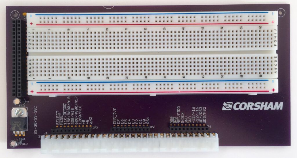
UPDATE The board above works fine for our system since we don’t have a chassis, but didn’t work well in a real SWTPC chassis without removing the back panel. A new version was laid out that fits entirely in a genuine SWTPC chassis but I’ve yet to order any blank PC boards for it.
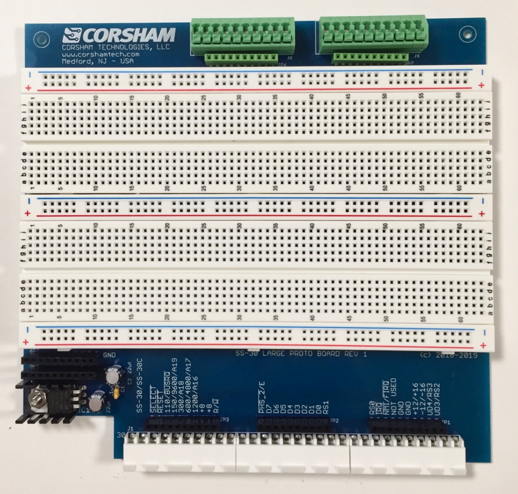
Large board
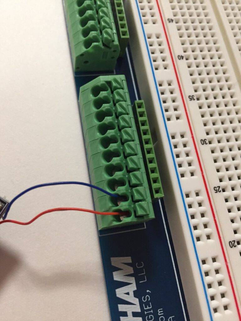
2019: Customers often come up with good ideas for new products or improvements to existing ones, and this was certainly one of those cases! Basically, he suggested adding more breadboard space, and adding a spring loaded connector on top for running wires to external circuitry. The resulting product is our new board:


On this page:
– SS-50 6800 CPU Power-On Reset
– SS050 FAQs
– SS-50 and SS-30 standards
Update (2/7/2021): Rather than using a 220uf electrolytic, use a 47 uf tantalum capacitor instead.
Update (2/5/2021): A previous version of this page said to add the capacitor to U1… that was incorrect! It is definitely on U4, the MC6875!
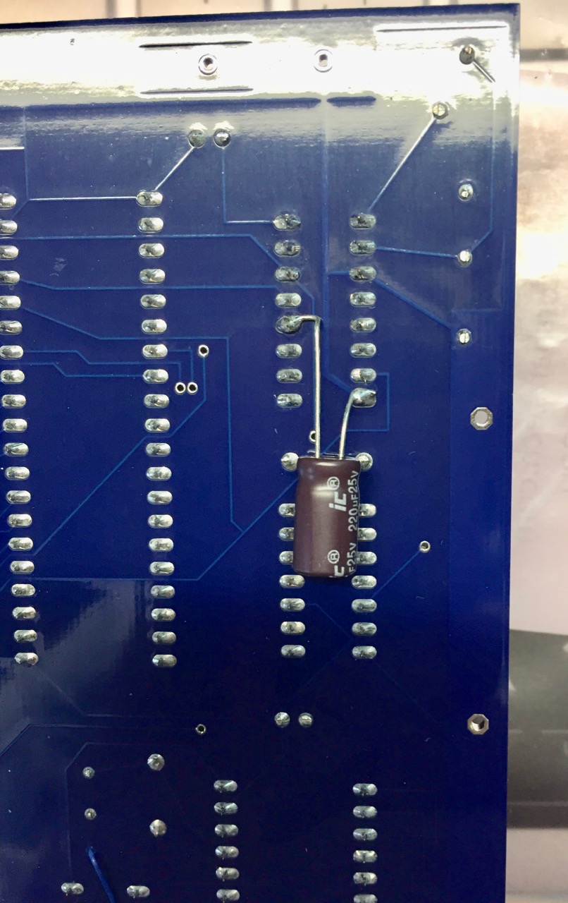
All existing versions, including up to 3A, of the SS-50 6800 CPU Board have a problem where power-on reset does not work. A part is missing. This is not a severe problem, as the user can press the RESET button on the board or the motherboard to do the reset, but it can be easily fixed.
You’ll need to solder a 47 uf, 16v (or higher) tantalum capacitor to the back of the board. The negative side of the capacitor goes to U4 pin 8 (ground) and the positive side goes to U4 pin 12. This is a picture from when I was using a much larger electrolytic capacitor, but I’ve switched to a 47 uf tantalum cap for all new boards:
All future revisions of the board will include this fix.
Q: Where can I get a copy of the SS-50 standard?
A: There is no standard, just a loose specification manufacturers followed when designing boards. The first SS-50 machine was from SWTPC and had a 6800 processor, so the buss was closely designed around that processor’s architecture. When SWTPC added a 6809 board they more-or-less followed the previous use of most pins on the buss, but also changed the purpose of others. Other companies began making compatible boards based on what was already on the market. To paraphrase Dr. McCoy of Star Trek fame, “Dammit Jim, I’m a buss, not a standard!”
Q: I keep hearing SS-50 and SS-30. Are they the same thing?
A: No, but closely related. The SS-50 buss is the main processor buss which includes all the address, data, and control signals needed to control the buss or respond to the processor board. It has 50 pins. The SS-30 buss is meant only for I/O. Decoding addresses takes a few chips that chew up real estate on a peripheral board and add cost, so SWTPC does the decoding on the motherboard and runs only essential signals to the peripheral boards. This is the SS-30 buss, and has 30 pins. Only a few address lines, data lines, and very few control signals.
Q: What are those strange connectors?
A: Those are Molex connectors which SWTPC used on other, non-computer, products. Hey, use what you’ve got in stock to save development time and stocking cost! They are still available from many sources, but the cost has gone up tremendously since they aren’t widely used anymore. The male connector with 10 pins, as used on motherboards is AMP/ TE Connectivity part number 1-640384-0, while the female connector used on plug-in boards is Molex/Waldom 09-48-2101. There is also a polarizing plug that goes into the female connectors and is Molex part number XXXXXXX.
Q: Which pin is pin 1 on both the SS-30 and SS-50 busses?
A: Technically, there were no pin numbers. SWTPC simply used the name of the line and never referenced a pin number. Many companies use http://www.cs.unc.edu/~yakowenk/swtpc/ss50.html as a guide, but I am aware of at least one board where the pin numbers were exactly the opposite direction.
Q: Boards don’t seem to plug in without a lot of force. Are you sure they are meant to plug into the motherboard?
A: Yes, the Molex connectors offer a lot of resistance at first but eventually get looser with insertions and removals. Make sure the polarizing plug is aligned properly with the missing pin on the motherboard. Some people insert a small screwdriver or used dental tool into each of the female connectors to loosen them up, but be very careful not to over-loosen them or else some of the pins might not make contact.
Q: Why are there so many pieces to build a complete system?
A: This is a clone, so it has an SS-50 buss for the CPU and memory, and an SS-30 buss for the peripheral devices. The original systems had a motherboard, CPU board, memory board(s), serial console board, terminal, etc, which means our system does too. Back in the day, people were driven by cost (just like now) so systems were modular, allowing someone to buy exactly what they wanted (or could afford) while building their system.
Q: What is the bare minimum to get started?
A: The motherboard contains the framework for the other boards to plug into, and is required. To use a terminal for a console, a serial board is required. We have two CPU boards, one having a 6800 and 16K of RAM, and a 6809 CPU with 128K. Only one CPU board is required.
Q: What can the bare minimum systems do?
A: Actually quite a lot, thanks to all the available software on the net. If you want to re-live the early days of the microcomputer revolution, there is plenty of RAM on either CPU board to load up Tiny BASICs, play games, write assembly language code, etc.
Q: How about mass storage?
A: We use our SD Card System. Our CPU boards include the low-level code providing drivers for the SD system, along with monitor commands to boot an operating system.
Q: What OS do you provide?
A: For the 6800, we use FLEX. For the 6809 we use FLEX/9 but have talked to various groups about multi-tasking operating systems. A different (still not released) I/O board is being developed to add additional capabilities for some OSes.
Q: An OS is great, but is there any software for those old systems?
A: Absolutely! Try looking at the FLEX User Group site: www.flexusergroup.com. They also have a large FTP site with a bunch of disk images. Drop those DSK files onto the SD card, mount the file as a disk drive, and you’ve got the disk contents for your use.
Q: So what do you guys do with YOUR systems?
A: I’ve got both 6800 and 6809 systems on the bench, both of which run FLEX, and are both a lot of fun to just program. I enjoy assembly language programming, so I’ve been working on some better tools for writing code.
Q: This stuff is all old technology, so shouldn’t it be cheap?
A: Sorry, this has a long answer. Some vintage parts are getting harder to find, demanding higher prices, or available in small quantities which have higher shipping costs. Some of these parts haven’t been manufactured since the early 1980s. Another big cost factor is that a lot of parts are needed, so while a more modern part might cost a few dollars more, the “more vintage” design sometimes requires several dozen of the older technology devices. Yet another factor is that the cost of printed circuit boards is based on the size of the board and the number being ordered. Ordering a single board might have a $70 set-up fee, and then $50 for the single board. Bumping up to 30 boards still has the $70 set-up fee, but the per-board cost might drop to $10. Given the size of the boards and the fact that each board has only limited functionality (as per the original design), the fixed prices are fairly high. This is a slightly political issue, but keep in mind the 25% US tax (it’s a tax paid by every American) on goods purchased from China, which is where a large percentage of electronic parts come from. Invoices from major US based suppliers show the dollar amount I had to pay in “tariffs” (it’s a tax) for that order.
Q: What else is needed, really?
A: Just a terminal and an RS-232 cable OR a personal computer with a serial port, cable, and a terminal emulator program. At shows we always use Wyse 30 terminals as they are available nicely refurbished for about $200.
Q: If I buy one, how hard is it to get running?
A: Before we ship a complete system, everything is plugged in, the system is brought up, then it is disassembled, packaged, and shipped. It’s really quite simple to plug in the boards and get running. Our suggestion is to set up just the motherboard, power supply, CPU board and serial board. Once your terminal is talking to the system, then it’s easy to plug in the parallel card, connect the SD card system, and boot into FLEX.
Q: Can I use Corsham Tech boards in a real SWTPC system or use SWTPC boards in a Corsham Tech system?
A: Absolutely! I sometimes bring several real SWTPC boards to demos, but they tend to draw a lot of current. Their 8K RAM board draws more than our complete 6809 system with a meg of RAM.
Q: Is there a case to put a system in?
A: No. It is expensive to have a case built unless we buy in very large numbers which we will probably never sell most of.
This isn’t really any definitive definition of the SS-50 bus, as boards were simply produced that worked with other SS-50 boards. When SWTPC devised the bus, they just made things work and other manufacturers made compatible boards. Years ago I found two sites that gave a clear description of the pins for both the SS-50 and SS-50C versions, and since they haven’t been touched in decades, I decided to copy the information here just in case the original pages ever go away.
The SS-50 was the main backplane in 6800 based SWTPC machines, and connected the CPU board with memory, disk controllers, and so on. As was common in that era, a board usually did just one thing, and did it well, so a system would have a CPU board, one or more memory boards, a serial board connecting to a terminal, and either a cassette I/O or disk controller board for program/data storage. Physically, the SS-50 bus consisted of rows of male Molex connectors, spaced 0.156 inches apart. The boards that plugged into it had the corresponding female connectors along one edge, rather than the more modern (and cheaper) printed-circuit contacts. The SS-50 bus had all signals from the processor. For I/O, see the section below about the SS-30 bus.
All signals starting with “/” are active low.
I/O was handled on a distinct 30-pin bus (the SS-30), which was generally similar to the SS-50 but had a “board select” signal instead of the address bus. The logic to select individual I/O boards in the SS-30 was hardwired to memory-map them into four-byte slots starting with board 0 at address $8000. Very few address lines from the SS-50 bus were present, usually only A0 and A1 (called RS0 and RS1) but the two UD (user defined) pins could have A2 and A3 connected to them.

(see also the Microchess page)
Downloads:
The hex file MicroChessOut can be loaded directly into the KIM CLONE and run from $2000
Archive with source.
Following the header "Peter Jennings, www.benlo.com" I was pleasantly surprised to see the website still active:
http://benlo.com/microchess/index.html
http://benlo.com/files/Microchess6502.txt
The source code Microchess6502.txt contains the additional note on line 35:
"; Updated with corrections to earlier OCR errors by Bill Forster, August 2005."
Line 73 comments on the cross-assembler used:
"BMCC = $E5 ; was BCC (TASS doesn't like it as a label)"
Looking for information about TASS led me to:
https://www.c64-wiki.com/wiki/Cross_Assembler
Reading from "64Tass/6502Tass: Another native "Turbo Assembler", developed for DOS (6502Tass), later also for Unix, Linux and Windows32 (64Tass)," I suspect the 1996-2002 code by Peter Jennings used the DOS version, but I am running Windows 10 on a modern laptop and I can't find a way to run 16-bit applications without using third party tools like DosBox or an emulator in VirtualBox.
So I decided to try out Tass64. I found a link to the Windows version on sourceforge, https://sourceforge.net/projects/tass64/. The documentation is included in the zip file, and also here http://tass64.sourceforge.net/.
Without really reading the documents, I just ran Microchess through the Assembler and got errors. Below are the errors I got, and how I fixed/hacked/patched each one.
First Attempt:
Error messages: 31
Warning messages: 3
Passes: 2
....Oof.....
Error Group 1:
MicroChessSource:37:8: error: general syntax
cpu 65c02
^
MicroChessSource:38:9: error: general syntax
page 0,132
^
Correction:
Change 37 to: .cpu "65c02"
Change 38 to ; page 0,132
Line 38 is commented out because 'page' "gives an error on page boundary crossing, e.g. for timing sensitive code" and I am simply going to put my faith in Peter Jennings and hope for the best here.
Line 37 can be changed to reflect the CPU you are using. I got my parts assembled by Bob, and leaving "65c02" as the cpu version works for me on the KIM CLONE.
Error Group 2:
MicroChessSource:729:6: error: general syntax
db $2c ; used to skip over LDA #$20
^
MicroChessSource:859:12: error: general syntax
Hexdigdata asc "0123456789ABCDEF"
Correction:
For all the lines that use "db" or "asc," change the pseudo-op to ".text"
Now I got:
-----------------------------------------------------------------------------
C> 64tass.exe -o MicroChessOut MicroChessSource
64tass Turbo Assembler Macro V1.55.2200
64TASS comes with ABSOLUTELY NO WARRANTY; This is free software, and you
are welcome to redistribute it under certain conditions; See LICENSE!
Assembling file: MicroChessSource
Error messages: None
Warning messages: None
Passes: 2
Memory range: $1000-$1524 $0525
Memory range: $1580-$15dc $005d
-----------------------------------------------------------------------------
I think I'd like to run Microchess from $2000 up in one block, so I will modify line 95 and 869:
Change line 95 to ";*= $1580"
and comment out line 869.
-----------------------------------------------------------------------------
Memory range: $2000-$2581 $0582
-----------------------------------------------------------------------------
Now the source will assemble, but it won't work yet. The Peter Jennings code with TTY was written for the "6551 Asynchronous Communications Interface Adapter (ACIA)," not the "standard TTY" routines built into the KIM monitor that we see in the First Book of KIM etc.
http://archive.6502.org/datasheets/mos_6551_acia.pdf
https://en.wikipedia.org/wiki/MOS_Technology_6551
First, I comment out the ACIA addresses from line 42.
;ACIADat = $7F70
;ACIASta = $7F71
;ACIACmd = $7F72
;ACIACtl = $7F73
Then, I add in the addresses of the KIM monitor TTY routines for getting (blocking) and outputting 1 character.
; http://www.zimmers.net/cbmpics/cbm/kim1/kim-hints.txt - See "KIM SUBROUTINES"
TTY_GETCH = $1E5A ; Register States: In to A, X preserved, Y = FF
TTY_OUTCH = $1EA0 ; Register States: X preserved, Y = FF, A = FF
Now, I move to line 822 and start making changes to the I/O Routines.
(1) Comment Out the Init function 825-829, don't need. I leave the label and rts to allow it to work as a dummy sub routine rather than deleting all references to it in the code.
(2) Replace the meat of "syskin" on 833 with code to push the affected registers, call TTY_GETCH, and restore affected registers.
(3) Replace the meat of "syschout" on 842 to push the affected registers, call TTY_OUTCH, and restore affected registers.
Now the code after line 822 looks like:
;
; 6551 I/O Support Routines
; Replaced with KIM Monitor Routines for KIM Clone - Neil 2020
;
;
Init_6551 ;lda #$1F ; 19.2K/8/1
;sta ACIActl ; control reg
;lda #$0B ; N parity/echo off/rx int off/ dtr active low
;sta ACIAcmd ; command reg
rts ; done
;
; input chr from ACIA1 (waiting)
;
syskin ;lda ACIASta ; Serial port status
;and #$08 ; is recvr full
;beq syskin ; no char to get
;Lda ACIAdat ; get
PHY
JSR TTY_GETCH
PLY
RTS ;
;
; output to OutPut Port
;
syschout ;PHA ; save registers
ACIA_Out1 ;lda ACIASta ; serial port status
;and #$10 ; is tx buffer empty
;beq ACIA_Out1 ; no
;PLA ; get chr
;sta ACIAdat ; put character to Port
PHA
PHY
JSR TTY_OUTCH
PLY
PLA
RTS ; done
IMPORTANT: I make use of the 6502 commands to push X and push Y, pop X, pop Y - PHX, PHY, PLY, PLX which work on the 65c02 but not the old-school 6502. This probably won't be an issue for the KIM Clone, but if it is, it will be necessary to change the way you push and pop using your favorite method from back in the day, of one of the examples here:
http://6502.org/tutorials/register_preservation.html
Now I re-assemble the source code, adding the flag to output INTEL HEX format. This is because Bob added support for intel hex to the [L] command on the KIM-1. There are programs on-line (somewhere) for converting and dealing with the KIM paper tape format, but being allowed to Load in INTEL HEX format allows us to output something the KIM CLONE can read without no trouble at all.
-----------------------------------------------------------------------------
C> 64tass.exe --intel-hex -o MicroChessOut MicroChessSource
64tass Turbo Assembler Macro V1.55.2200
64TASS comes with ABSOLUTELY NO WARRANTY; This is free software, and you
are welcome to redistribute it under certain conditions; See LICENSE!
Assembling file: MicroChessSource
Error messages: None
Warning messages: None
Passes: 2
Memory range: $2000-$256e $056e
-----------------------------------------------------------------------------
Now, I could use SecureCRT or Tera Term or some other fancy terminal to send the file as ASCII when I press the [L]oad command on the KIM-1. Today, however, I will use the humble PuTTy terminal emulator. And simply copy the hex to my clipboard, and paste it in PuTTy after pressing the [L] command.
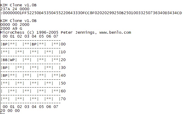
KIM Clone v1.0B
237A 24 0000
:00000001FF52250D45350455220643330FCC8F02020299250B25010033250736340D3434CD
KIM Clone v1.0B
0000 00 2000
2000 A9 G
MicroChess (c) 1996-2005 Peter Jennings, www.benlo.com
00 01 02 03 04 05 06 07
-------------------------
|BP|**| |**|BP|**| |**|00
-------------------------
|**| |**| |**| |**| |10
-------------------------
|BB|WP| |**| |**| |**|20
-------------------------
|BP| |**| |**| |**| |30
-------------------------
|BP|**| |**| |**| |**|40
-------------------------
|**| |**| |**| |**| |50
-------------------------
| |**| |**| |**| |**|60
-------------------------
|**| |**| |**| |**| |70
-------------------------
00 01 02 03 04 05 06 07
20 00 00
?C
MicroChess (c) 1996-2005 Peter Jennings, www.benlo.com
00 01 02 03 04 05 06 07
-------------------------
|WR|WN|WB|WK|WQ|WB|WN|WR|00
-------------------------
|WP|WP|WP|WP|WP|WP|WP|WP|10
-------------------------
| |**| |**| |**| |**|20
-------------------------
|**| |**| |**| |**| |30
-------------------------
| |**| |**| |**| |**|40
-------------------------
|**| |**| |**| |**| |50
-------------------------
|BP|BP|BP|BP|BP|BP|BP|BP|60
-------------------------
|BR|BN|BB|BK|BQ|BB|BN|BR|70
-------------------------
00 01 02 03 04 05 06 07
CC CC CC
Personal Notes:
-The extended monitor on the KIM Clone has extra for string printing and more, so if I was doing a serious "KIM CLONE" port, I might look at rewriting a lot of the drawing functions.
-It is really clunky how the screen re-draws after every CHARACTER -- which means I have to sit through 4 board redraws just to enter a move. I want to update that code, because I don't have pre-digital age patience.
-My cross compiler of choice is ca65, part of the cc65 C compiler for the 6502. Maybe a ca65 port of the syntax is something I might try.
There are great usage notes for this version of the game here:
https://obsolescence.wixsite.com/obsolescence/kim-uno-microchess
Too late now, but I notice he went through the exact same process changing the UART routines for his version of MicroChess for the Arduino KIM-1 emulator.
KIM monitor as modified for the Corsham Tech KIM Clone board.
Notable changes:
* Removal of the code to save/load from cassette tape.
* Lunar Lander (First Book of KIM) added.
* Famer Brown (First Book of KIM) added.
* New X command from TTY to enter the Corsham Technologies xKIM extended monitor.
See also the Corsham github page.
Download the KIM Monitor repository copy here.
Note that you can use the standard KIM ROMs also, the KIM Clone is a KIM-1.
xKIM
xKIM is an extended monitor for KIM computer systems. Commonly used in Corsham Technologies KIM-1 add-on boards.
It is a 6502 based monitor which has basic tools as well as some additional commands for working
with the Corsham Tech SD Card system.
Features
* Pure 6502 code.
* Many subroutines available for external programs to use.
* Can auto-run Intel hex files upon loading.
* Can be placed in read-only memory.
* Has all low-level subroutines for talking to the SD Card.
* New commands can be added at run-time to the command handler.
Command Summary (not a complete list)
* Examine/edit memory.
* Jump to code.
* Load Intel hex file from console or SD card.
* Directory of SD card.
* Get clock from RTC.
* Memory test.
* Branch offset calculator, also within memory editor.
* Type SD file.
* Save memory to SD file.
Downloads
xKIM-master 2021
xKIM older versions
![]() |
xKIM Manual 1.6 |
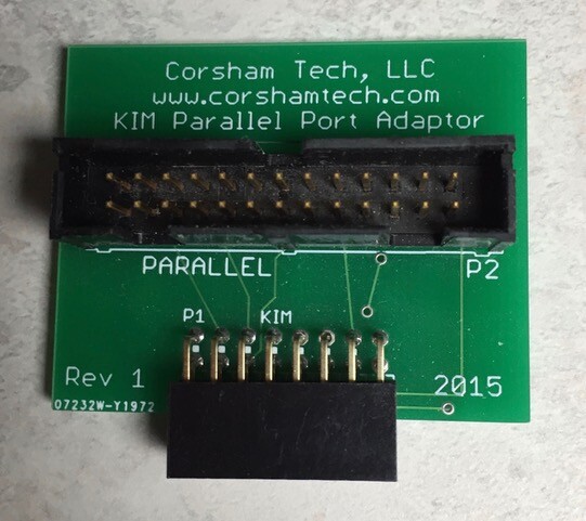
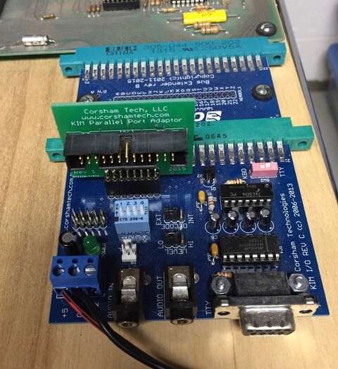
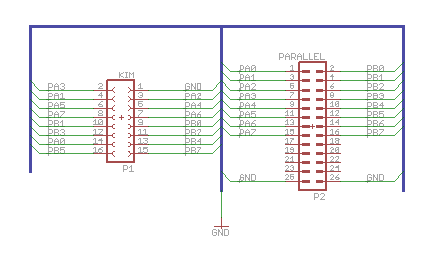
A small project to convert the connector on the KIM I/O board to a Parallel Port adapter (2021).


Getting enough memory and bringing up a BASIC interpreter were early goals of many personal computer users back in the 1970s. While Dr Dobb’s Journal was printing a new small BASIC interpreter for the 8080 almost every month, 6502 users were left out in the cold. Fortunately, Tom Pittman produced a Tiny BASIC that he charged $5 for. Microsoft also ported their full floating point BASIC but it was not cheap.
Nowadays the source code for these and other BASIC interpreters are freely available on the internet but usually require the user to jump through some hoops to use them. Ie, setting up a build environment. To make things a bit easier, I’ve put binaries and some sources on this page. These are all quite runnable on a KIM-1 with extra memory. There are no interpreted languages that I am aware of that will run in the 1K KIM-1 although Tiny PILOT from Compute magazine can run in 2K, that’s what I used.
Tom distributed a very small BASIC that needed about 3K to run, and was available on paper tape for $5!!! He has quite a bit about it at:
http://www.ittybittycomputers.com/IttyBitty/TinyBasic/
On there is a KIM-1 version that annoys me a bit. Tom and I worked about 10 years ago to disassemble and produce a really good source code package with a lot of my reverse engineering and his comments about portions of the code he could remember details of. For some reason he put up a poorly commented version Here is the source code, listing, and binary to my disassembly which includes a lot of comments and notes from Tom:
A ready-to-run binary which loads at $0200 and should have RAM up to $13FF
(see also the Tiny Basic page)
First, here are complete instructions for building your own version Install the CC65 package, then run the make.sh command, then look at the file tmp/kb9.bin, You’ll need to convert that raw binary image to a file suitable for downloading to the KIM.
Or just use my binary. All of these needs at least 12K of RAM starting at $2000.
(see also the Microsoft Basic page)
Create your own Version of Microsoft BASIC for 6502” — pagetable.com
Here is a file suitable for downloading onto a KIM-1. It loads at $2000 but to run it you’ll need to start at $4065. Use the L command in KIM-1’s monitor, then upload the file. I strongly suggest that you change your terminal emulator so it adds a 200 ms pause at the end of each line. Once it loads, run it by going to 4065 and running it at $4065 G; To see the easter egg, answer “A” when it asks for memory size.
Original KIM-1 Microsoft BASIC: kb9
This is still experimental but I have a version which uses functions in the xKIM monitor (present on the KIM Clone or on the 60K RAM/EPROM board) to save/load from the SD Card System. It also has a DIR command. This is an Intel HEX file and must be loaded from the xKIM “L” command:
This loads and runs at $2000.
All the early issues of Dr Dobb’s Journal discussed using using an intermediate language (IL) to write a general interpreter, then writing a BASIC interpreter using the IL language. Nobody used this except for Tom Pittman. I liked the idea and about five years ago wrote my own BASIC using that approach. It is buggy, but the sources are on github so anyone can take them, hopefully debug things, and put fixes back in place. My version also has commands to save/load programs to/from a Corsham Technologies’ SD Card System.
Source code:
And a binary version that can be run starting at address 0200:
Versions:
2019 archive
2021 archive
![]() |
Bob’s_Tiny BASIC |
When we began building the first of our SS-50 series of cards, the most common request was for a mass storage option. Those old disk controllers are hard to find on the surplus market and the old disk drives are getting harder to maintain. While we like vintage equipment, sometimes it’s worth using some modern technology to do updates.
Enter our SD Card System.
This is a two board system that provides a very inexpensive, flexible, and long-lasting storage option for our KIM Clone , SS-50 based designs, or almost any third party system.
The main board is our SD Shield. It plugs into an Arduino Mega and provides for insertion of a micro SD card, and also includes a DS3231 based real time clock (RTC). The Arduino does the hard work of providing an interface between the host processor (6502, 6800, 6809, etc) and the SD card and RTC. It connects to the host via a ribbon cable.
The board also contains three LEDs used for status, a RESET switch, a four position DIP switch, a DS3231 RTC, backup battery, and it maintains the Arduino Mega headers so additional shields can be placed on top. Since the source code is available you can add additional drivers for whatever shields you add. Want to add an LCD shield that displays which files are mounted? Just plug in the shield and modify the user interface class in the source code. Only one of the DIP switches has a defined purpose, so the rest are free for you to add your own logic.
The protocol between the host and the SD Card System is completely defined in The Remote Disk Protocol Guide.
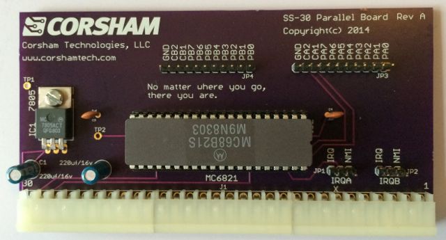
In order to use this card on an SS-50 based system, you will also need a parallel card such as ours.


![]() |
SD Card System 2015 |
![]() |
SD Card System 2017 |
![]() |
SD Card System 2021 |
![]() |
The Remote Disk Protocol Guide August 2015 V0.1 |
![]() |
The Remote Disk Protocol Guide April 2017 V1.1 |
Downloads
Drivers for 6502, 6800 and 6089 Flex, Arduino Mega Firmware, SD Images Flex, older versions also
Firmware 2021
Test program for SD Shield
Clock utilities set time and date from KIM-1
Reproduction and uptodate SD Shield by Eduardo Casino (Github copy)

The schematic above is the only version posted. It is not the latest schematic used by Bob (see below). Eduardo Casino (see the download above) reverse engineered the SD Shield and produced an uptodate version 9.
April 5, 2021 New Version of SD Card Shield

This is another board done entirely with KiCad and rolls in a few changes from the previous boards. It is completely compatible with the rev 8 boards, which were compatible with rev 7, which were compatible with… etc, etc, etc.There is no new revision of Arduino code for this board.
No new features but a few changes:

The rev 9k1A will eventually be changed to just rev 9, as there is no need to keep KiCad revisions uniquely identified.
Sometimes it’s nice to just enhance an existing product, especially when the supply of blank boards starts running low and more need to be ordered. I’m running low on the SD shields so it was a good time to make some improvements. This is a prototype:

The changes from the Rev 4 boards:
There will eventually be a Rev 6 with the new pull-down resistor and maybe the two pull-ups removed, but I’ll use the current Rev 5 boards and manually add the pull-down for now.
The RTC is completely software compatible with the current boards so any version of our Arduino code will work with it.