
After publishing the photos of the transistors used in the KIM-1 a discussion started on forum64.de in the ‘Instandsetzung und Nachbau eines Kim-1’ thread about some transistors were placed wrong in later revisions. And the KIM-1 involved functions well.
The User manual states:
 --------+-------------------+------+---------------------------------------
 | ITEM  | PART              | QTY. | DESCRIPTION                          |
 +-------+-------------------+------+--------------------------------------+
 |  18.  | Q7                | 1    | NPN Transistor B>20, VCE>12 - 2N5371 |
 |  19.  | Q1 through Q6     | 6    | PNP Transistor B>20, VCE>6  - 2N5375 |
 --------+-------------------+------+---------------------------------------
which are quite generic general purpose transistors.
MOS Technology used those parts in the first edition, Rev A and Rev B. Commodore then took over and parts used changed to equivalents.
In my KIM-1 collection I have found (see also the list in this page, Q1..Q6 also have this quirk on some KIM-1s)
Transistor Q7
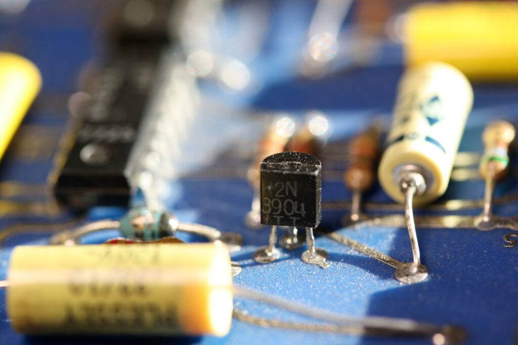
Rev D 2N3904
Rev E 2N3904
Rev F 2N4401
Rev G 2N4401
Rev G 2N4401
which are functionally equivalent, but have a different pinout. But are placed exactly like the 2N5371.
My first KIM-1, Rev F has a BC239C, which is OK, my trusty old KIM-1, functioning perfectly over the serial interface with thsi CBE transistor.
The 2N5371 pinout is CBE, Collector Base Emitter. The 2N3904 and 2N4401 are EBC.
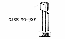
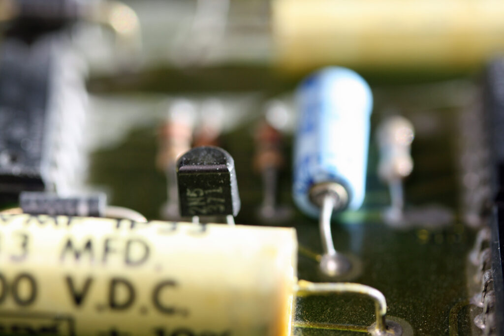
2N5371 pinout
The actual pinout of the 2N5371 is CBE. The letters in the image are beneath the actual wire, and the Base wire is bent to the back.
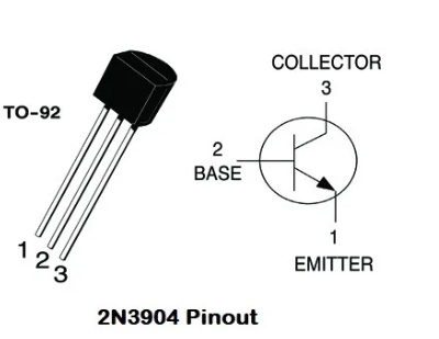
2N3904 pinout
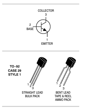
2N4401 pinout
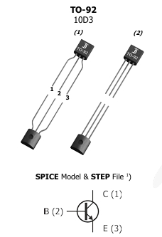
BC338 pinout
Those are EBC pinouts. But they are placed exactly like the 2N5371, which is CBE. It should be the other way around. But it works!
On the Rev D Replica by Eduardo Casino and the Nachbau KIM-1 by Ralph02 the BC327(2N5375) and BC338(2N5371) are used. These have the same pinout.
How does that work?
Well, it seems that it does not matter here. An NPN transistor can be wired this way, exchanging Collector and Emitter. It functions the same, but the specs are much worse like the amplification factor. Since this is an emitter follower and the input voltage can be (via a limiting resistor to be added) go to 5V it works reliable.
Part of the KIM-1, the TTY serial interface