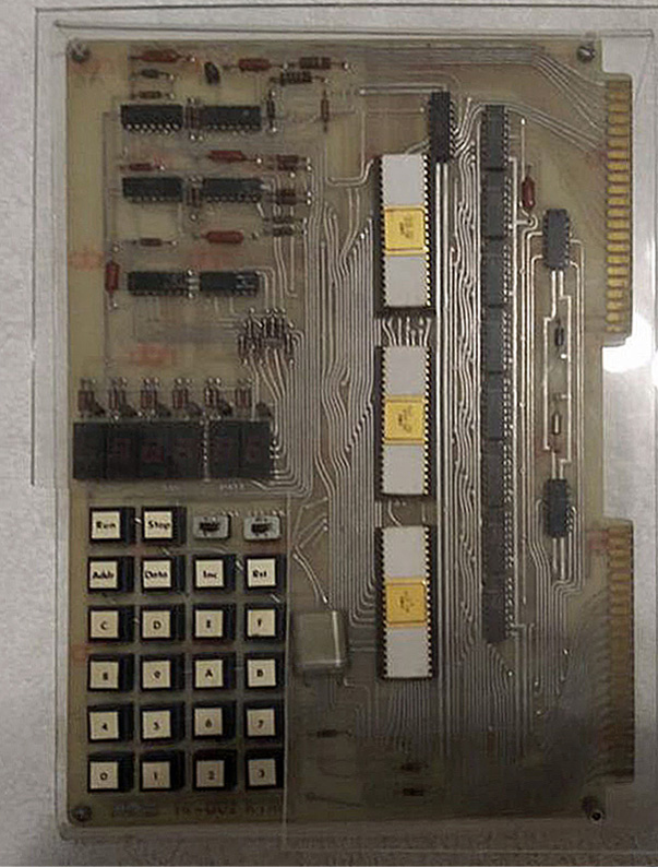
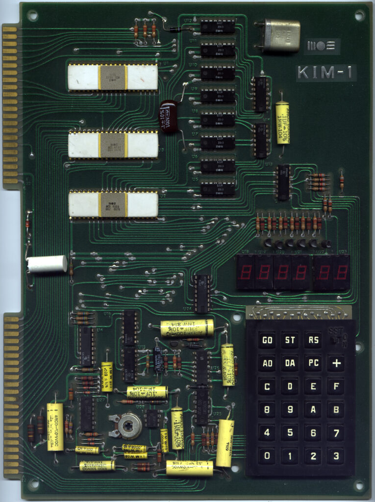
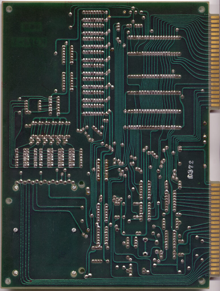
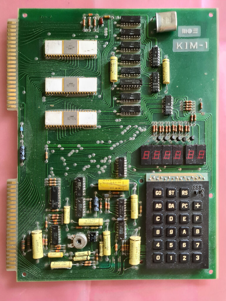
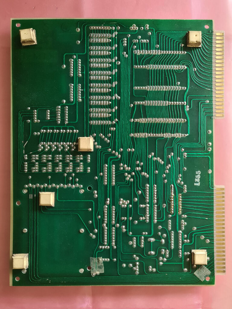
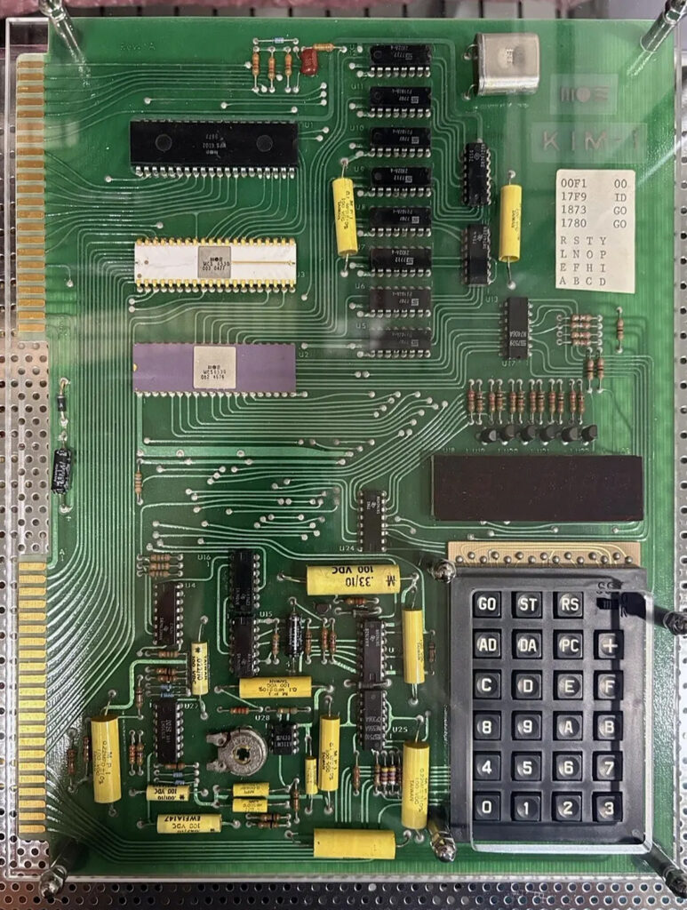
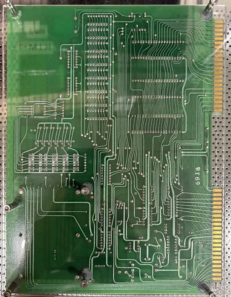
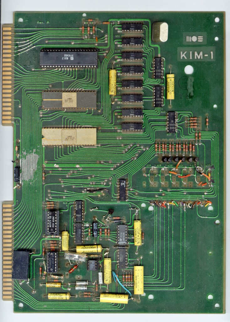
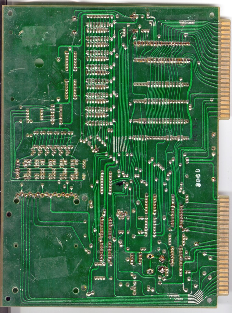
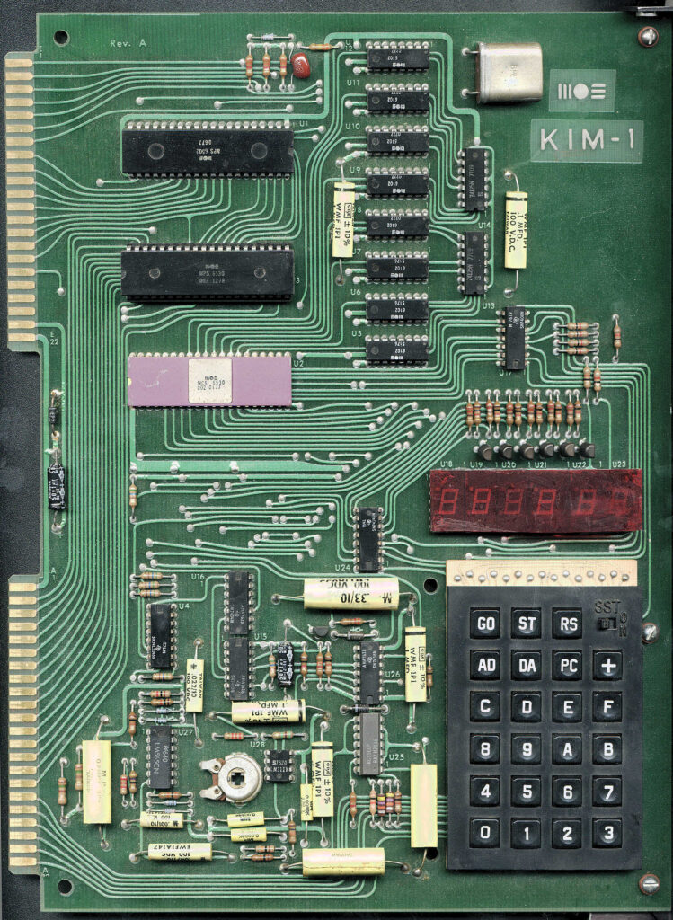
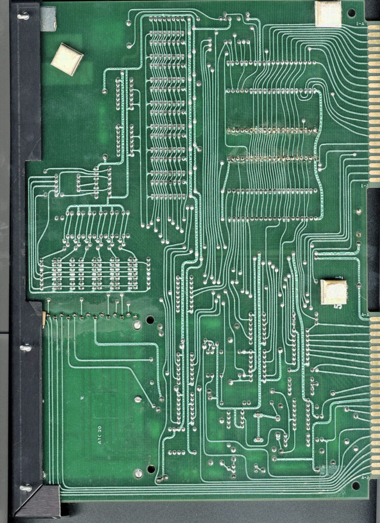
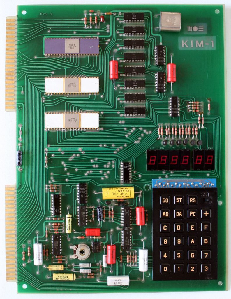
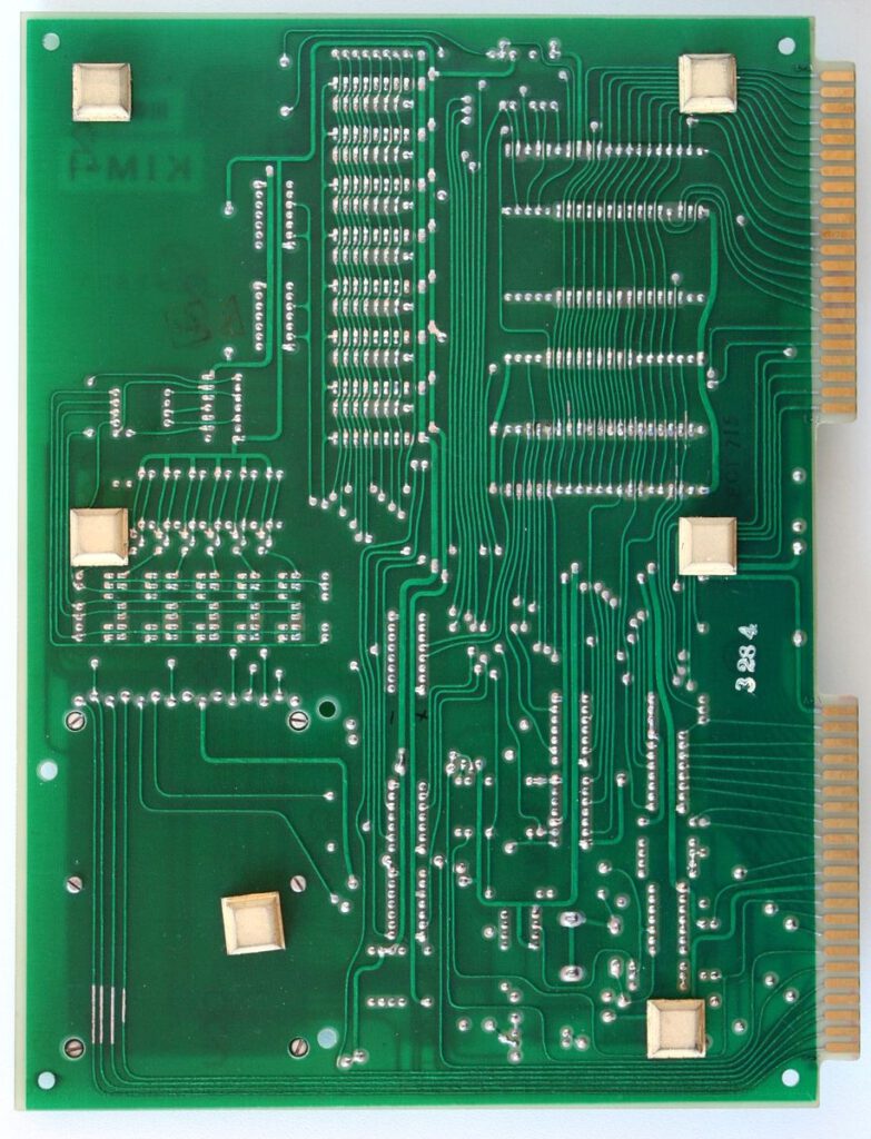
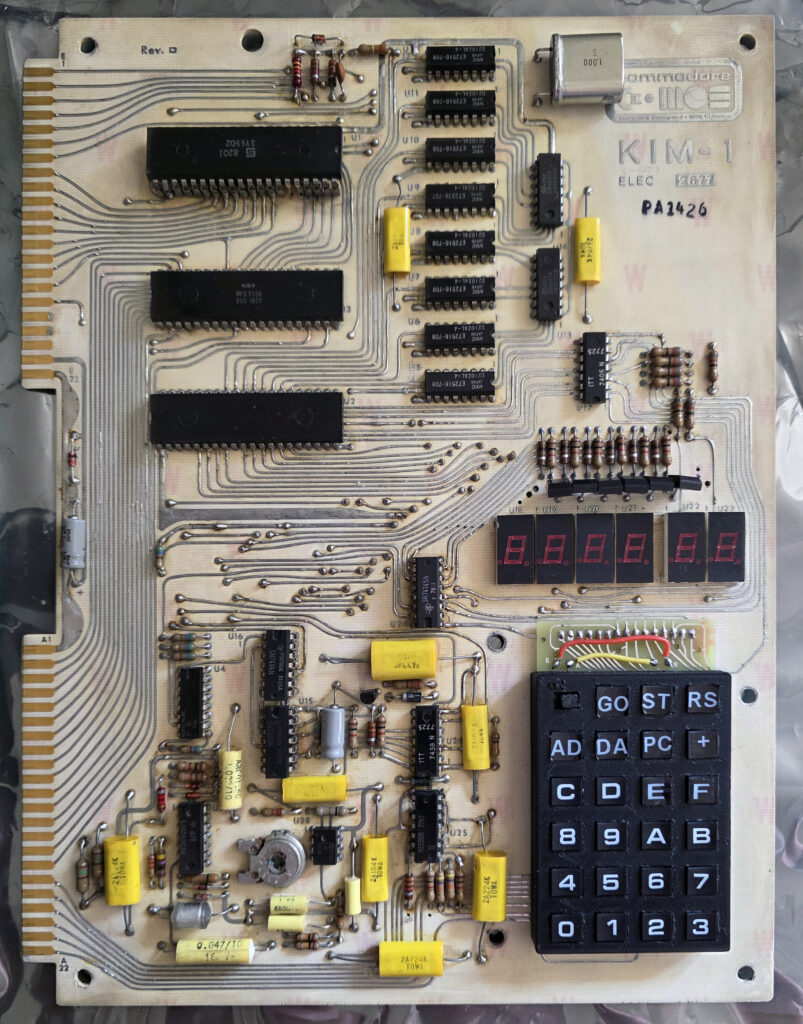
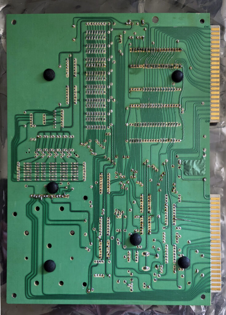
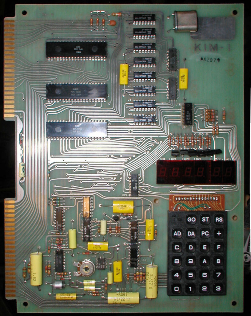
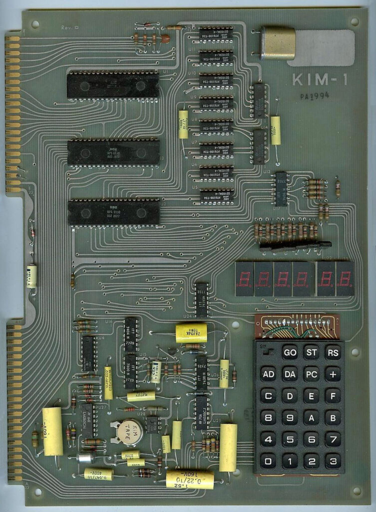
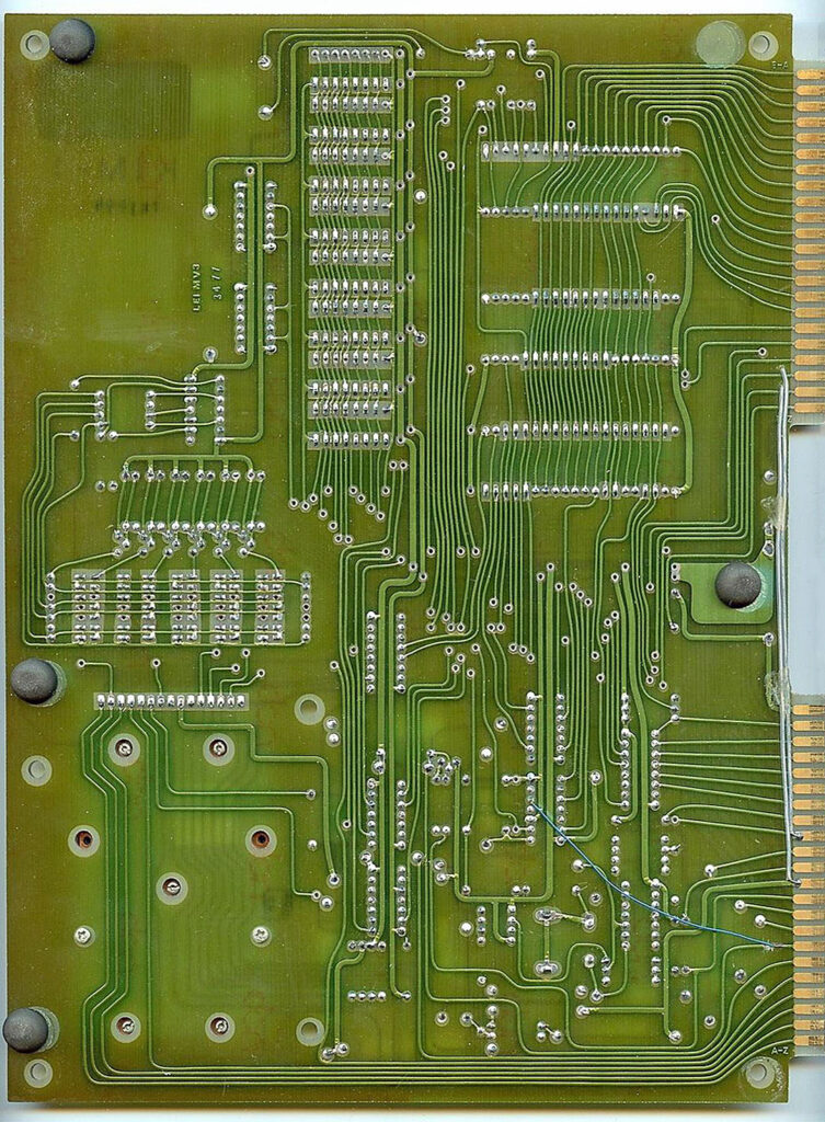
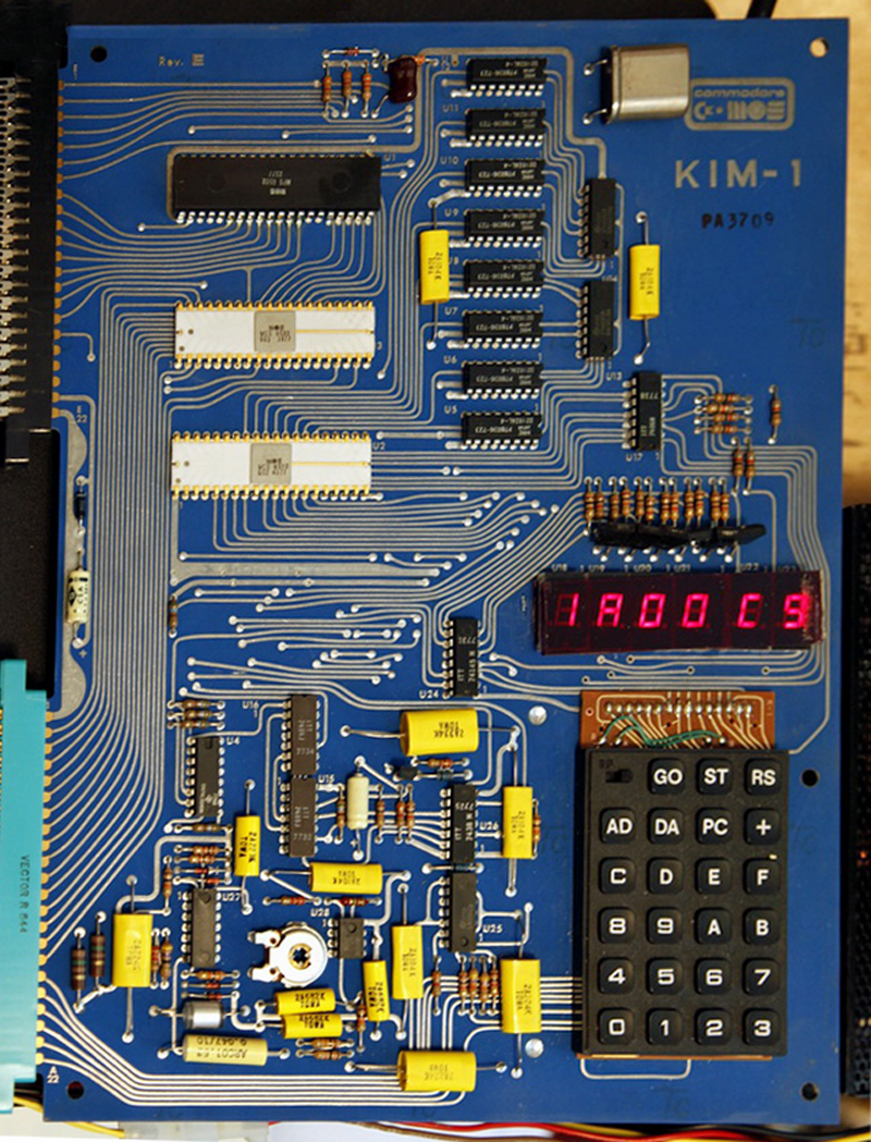
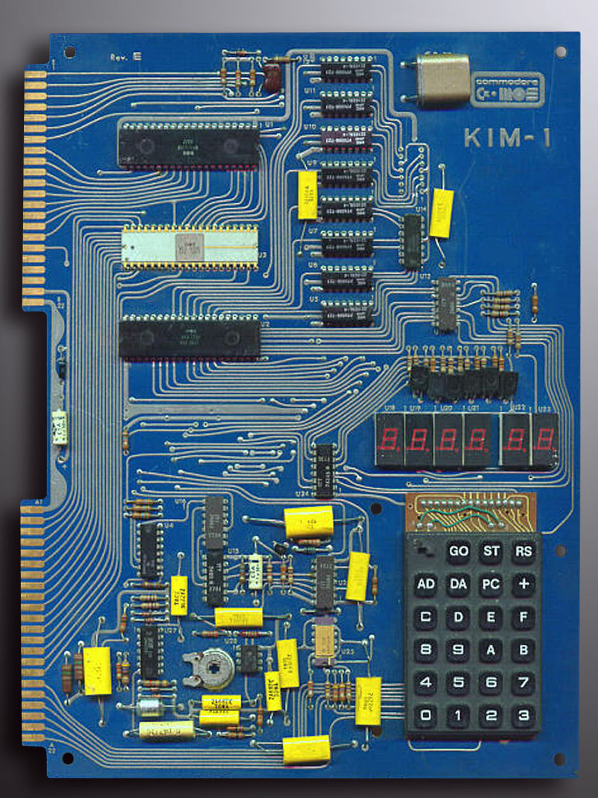
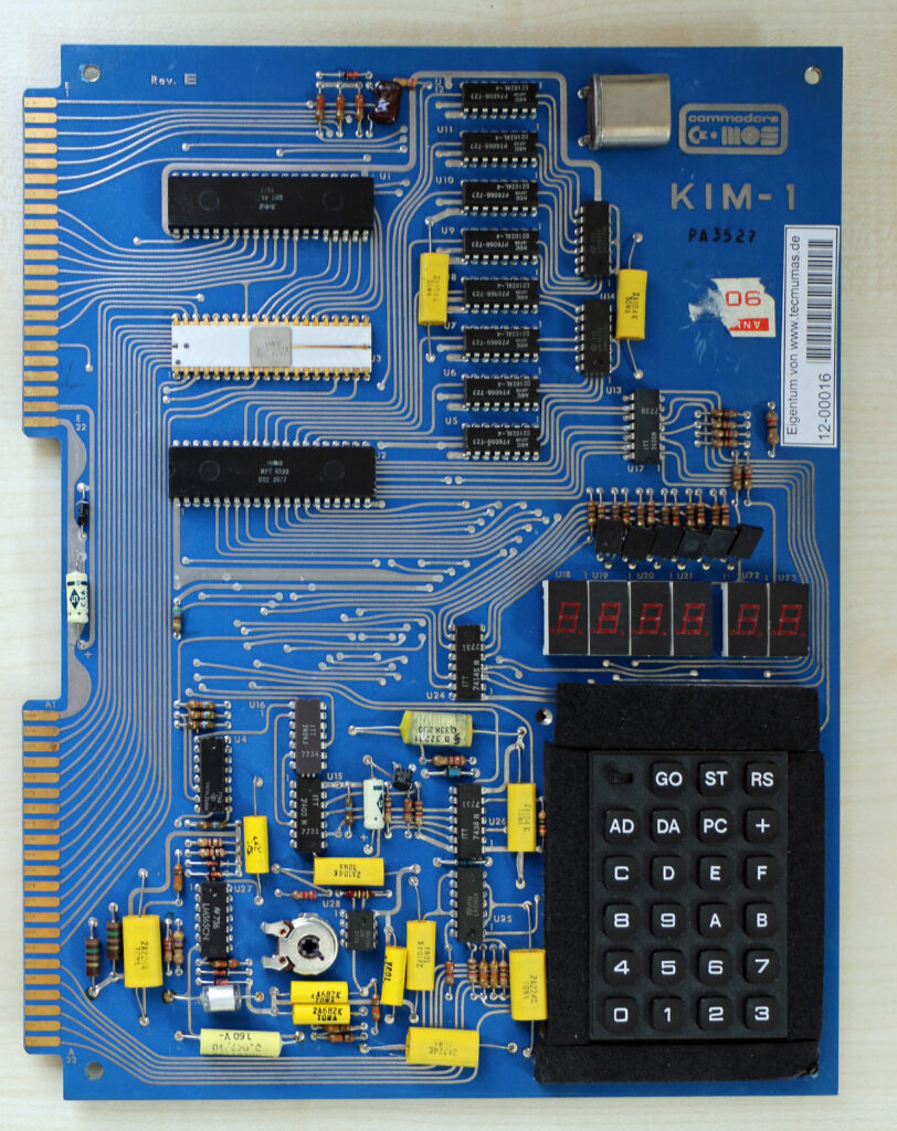
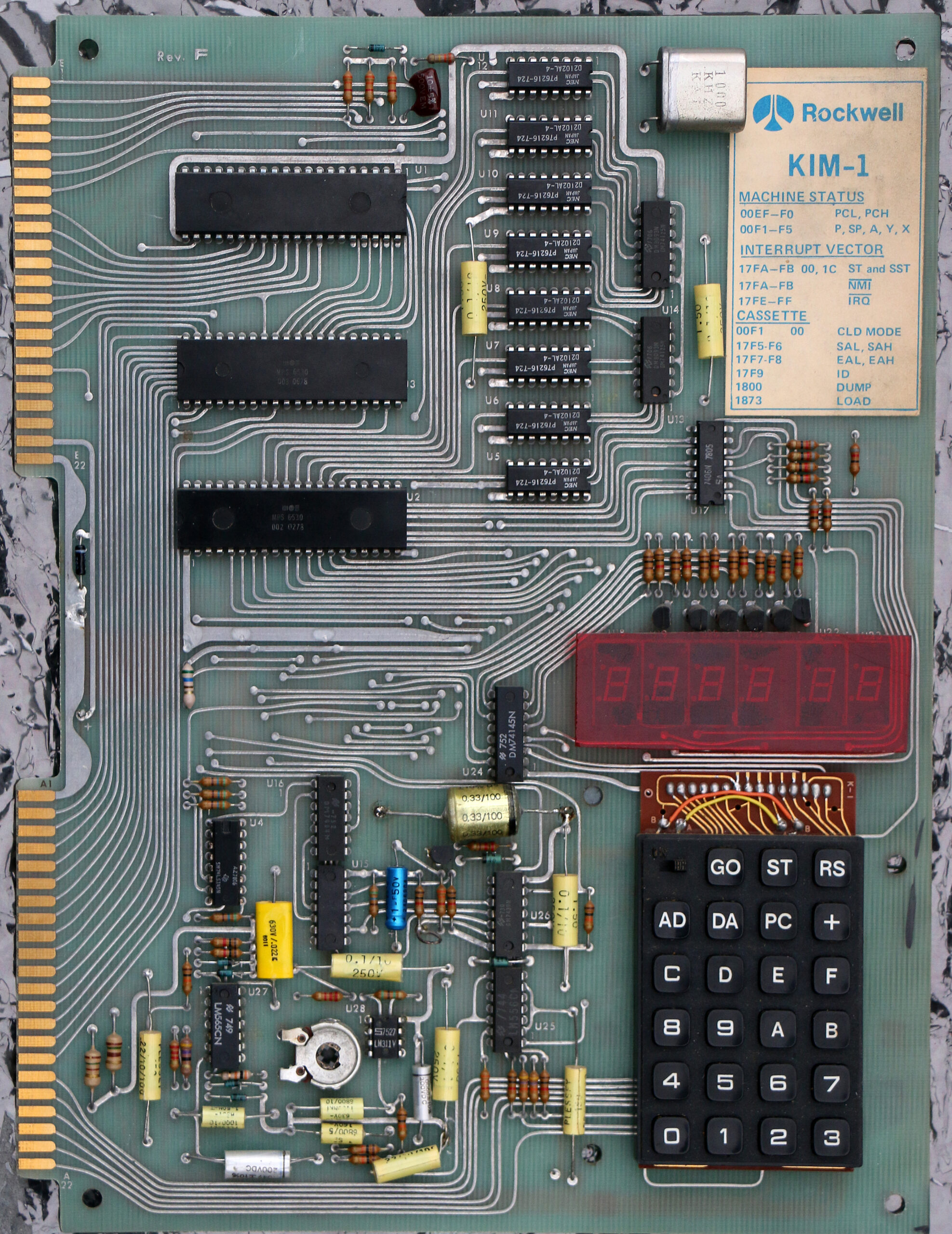
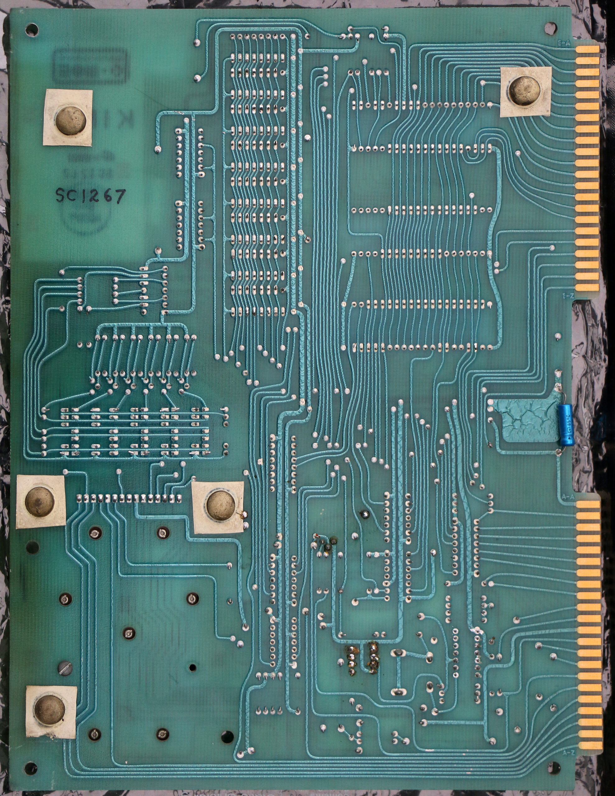
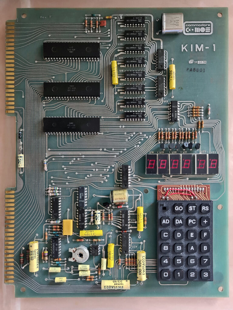
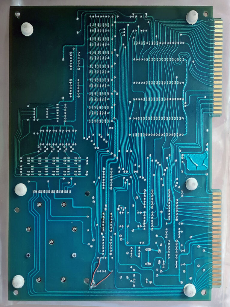
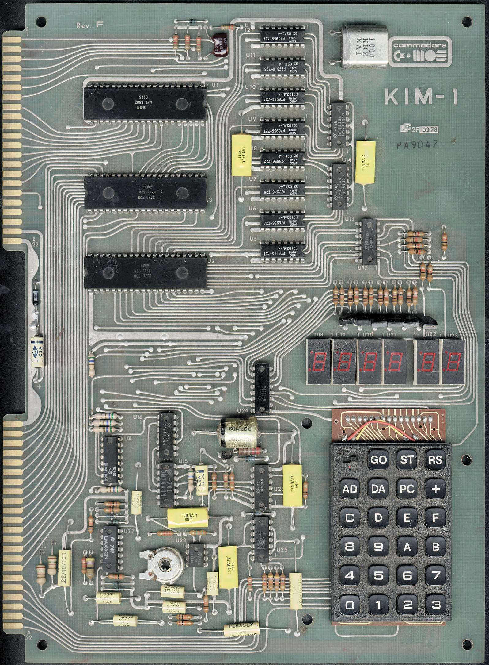
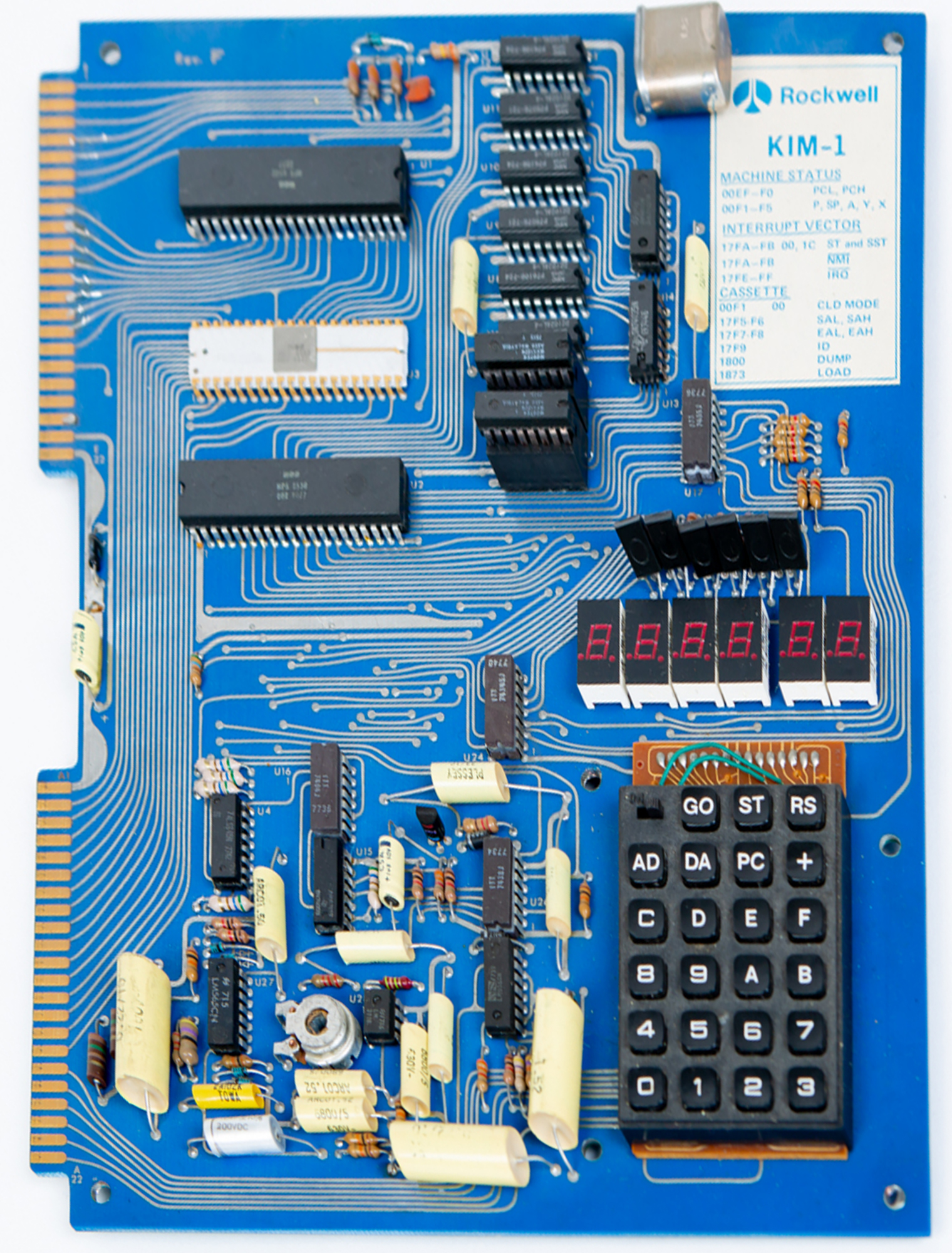
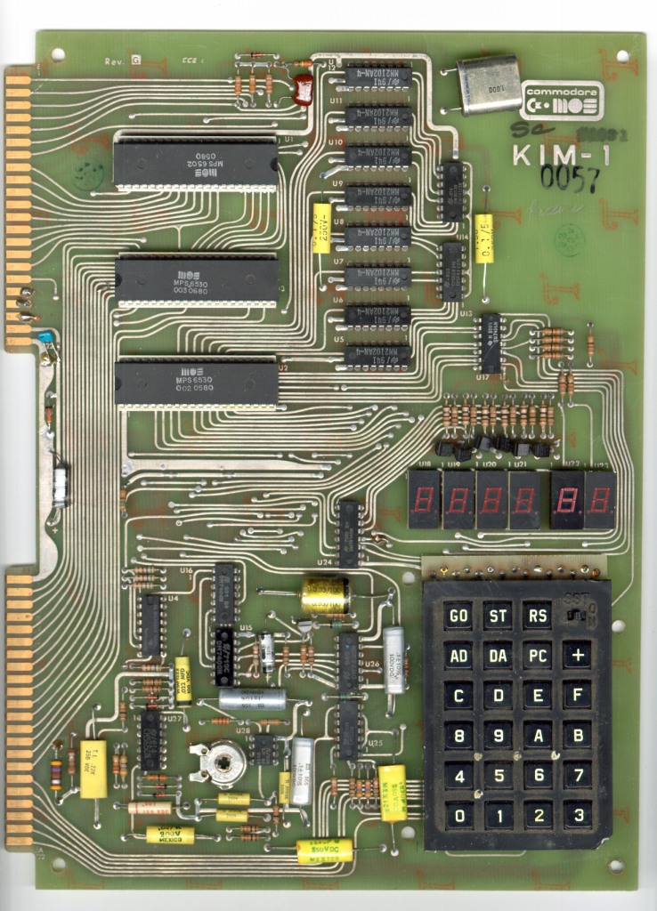
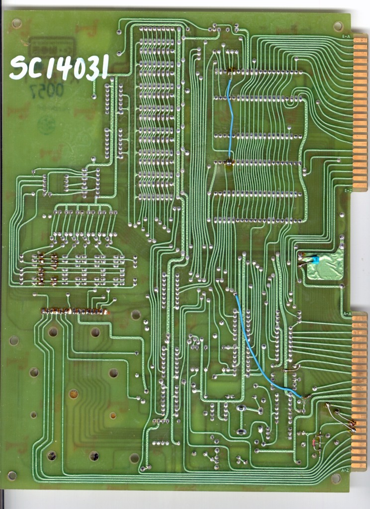
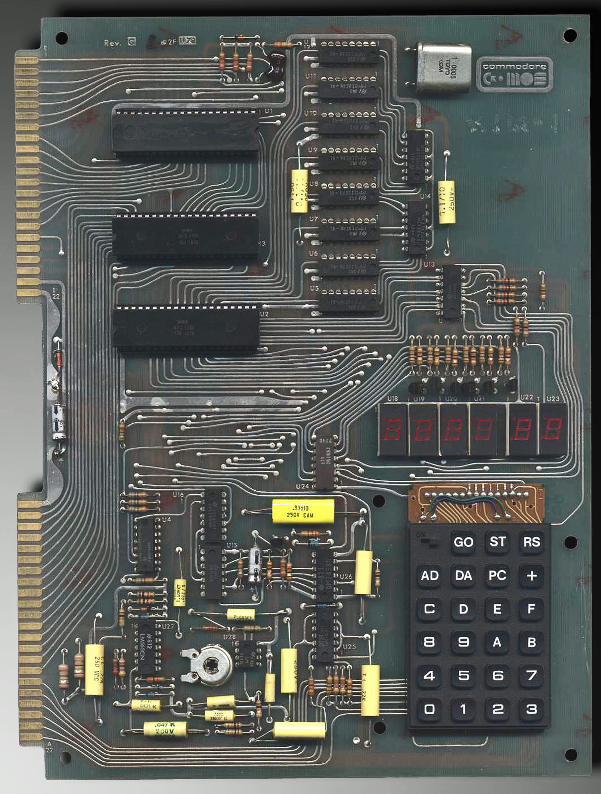
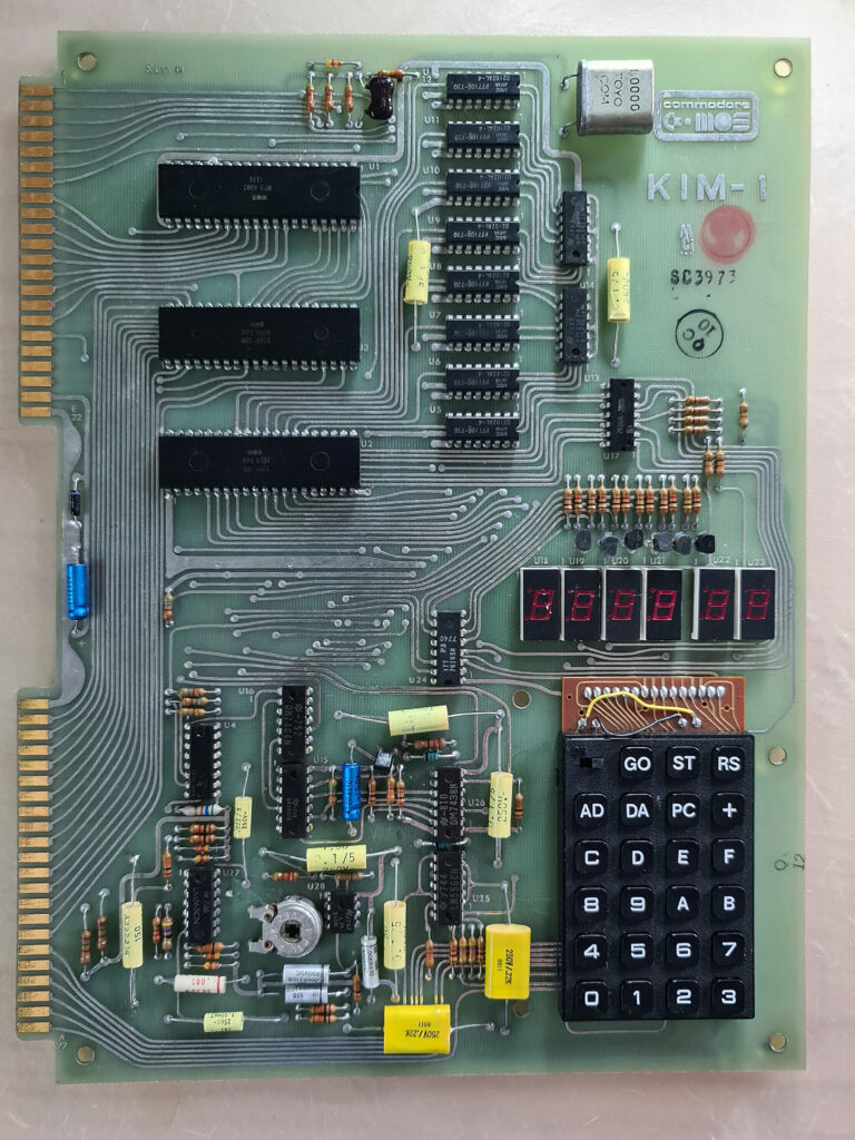
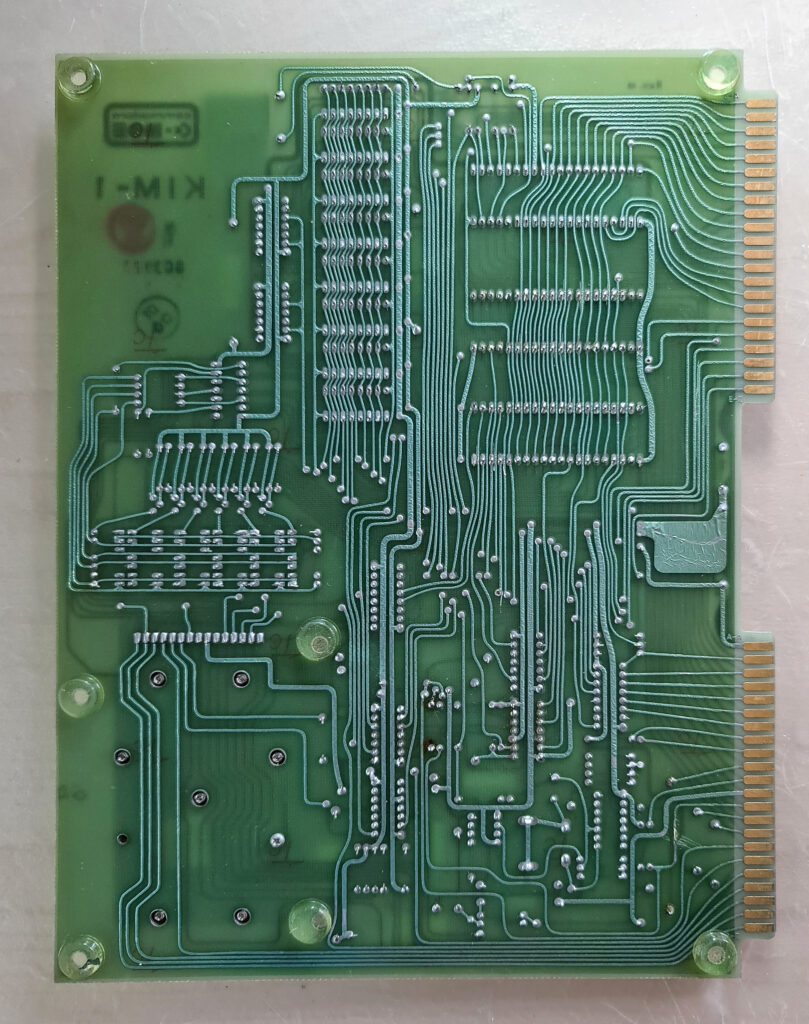
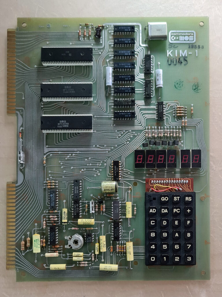
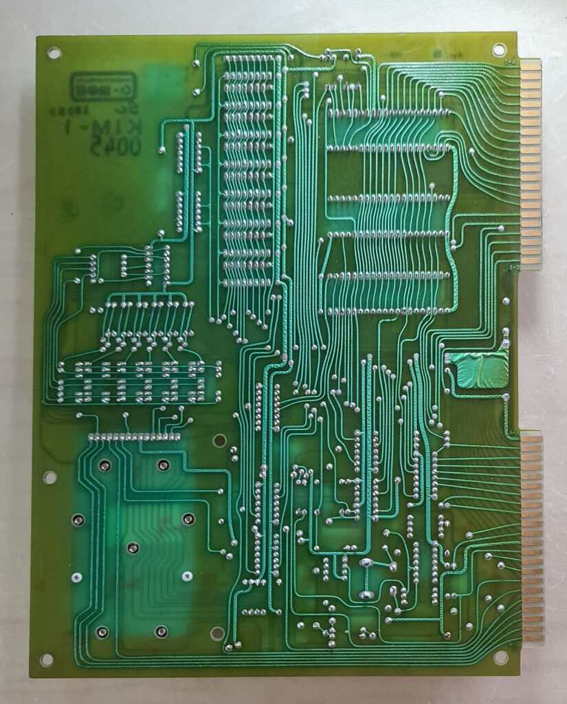
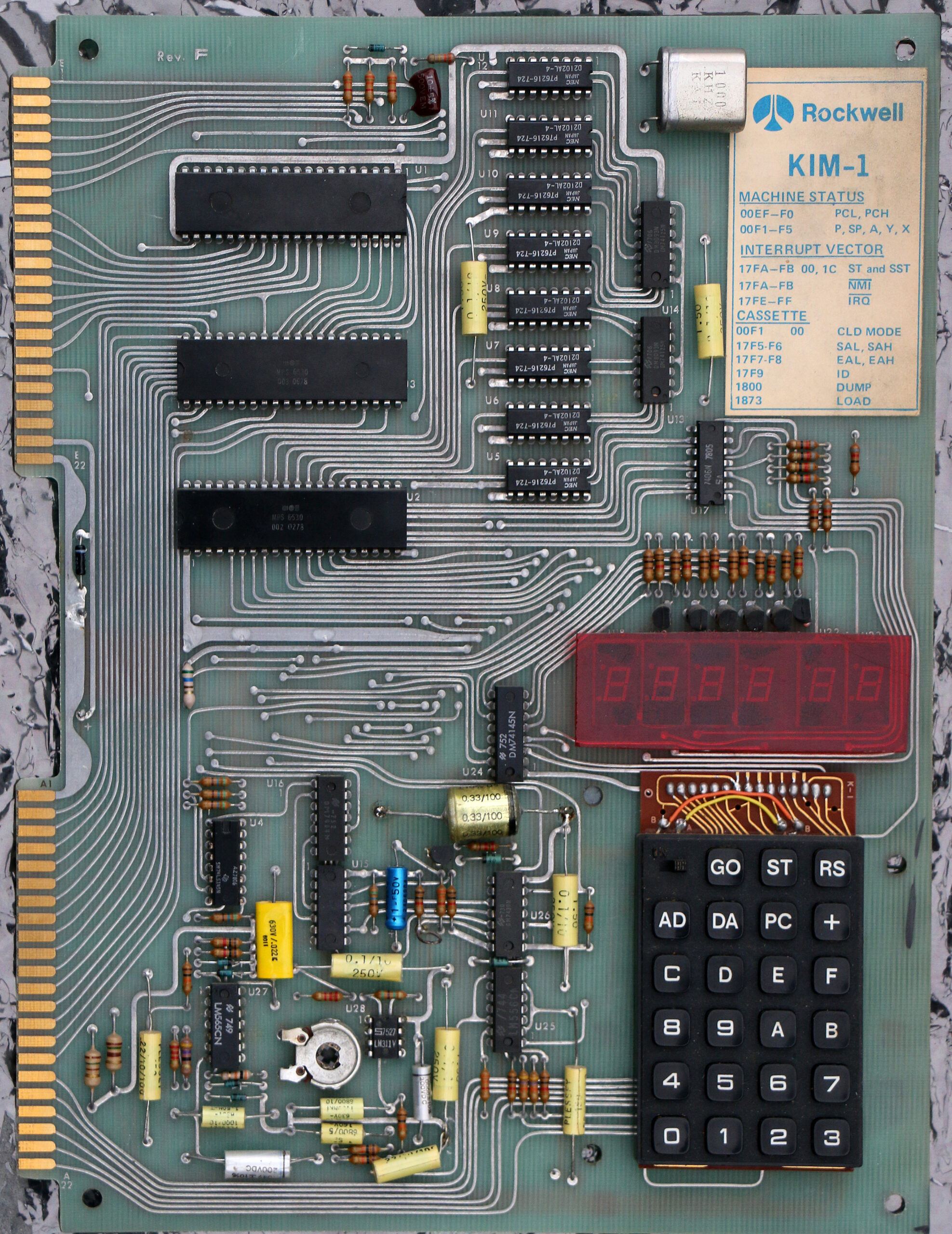
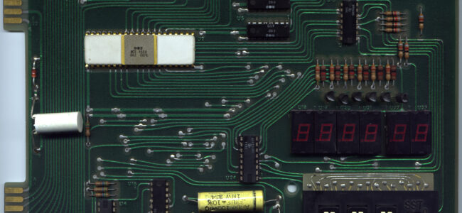
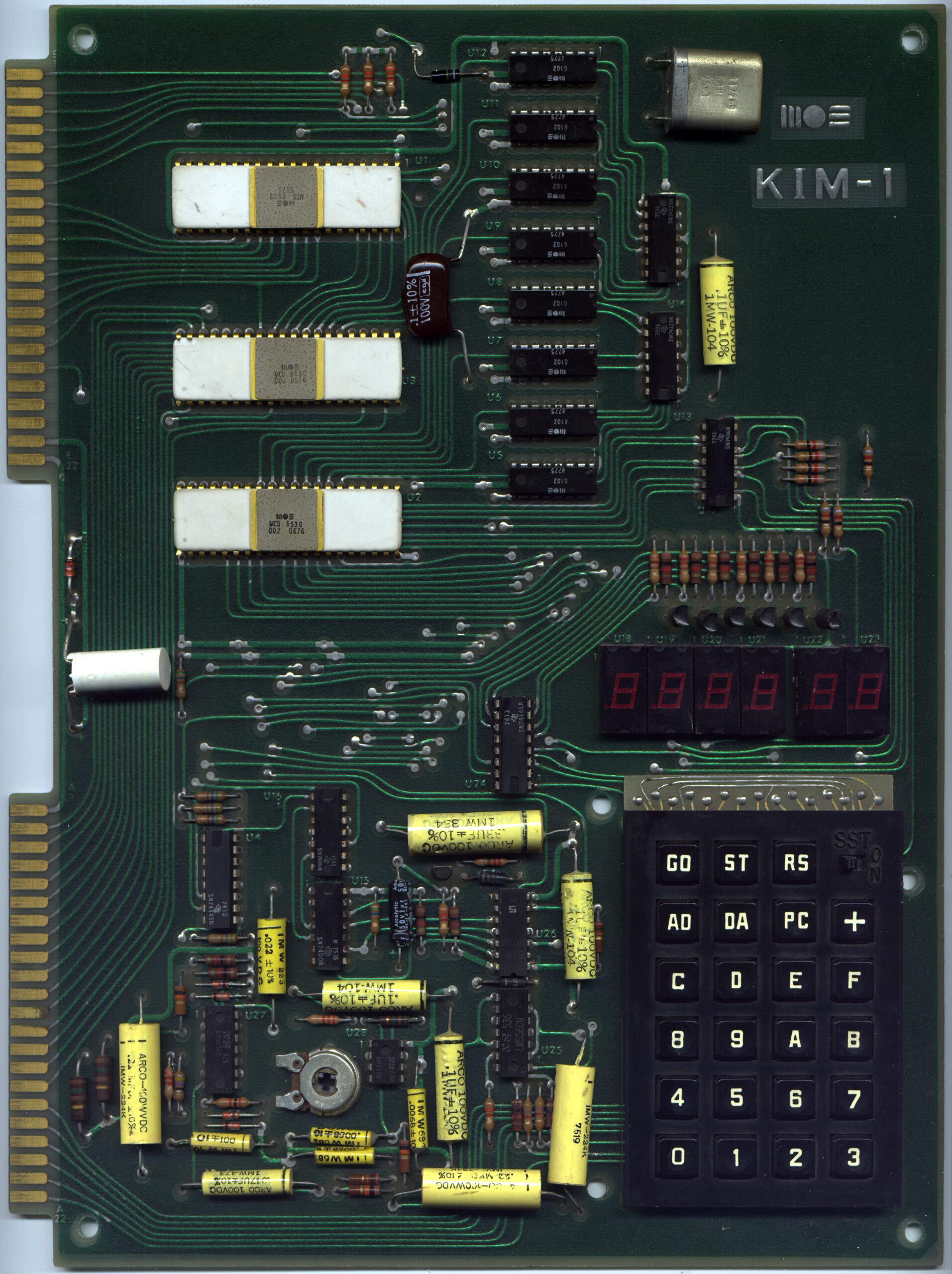
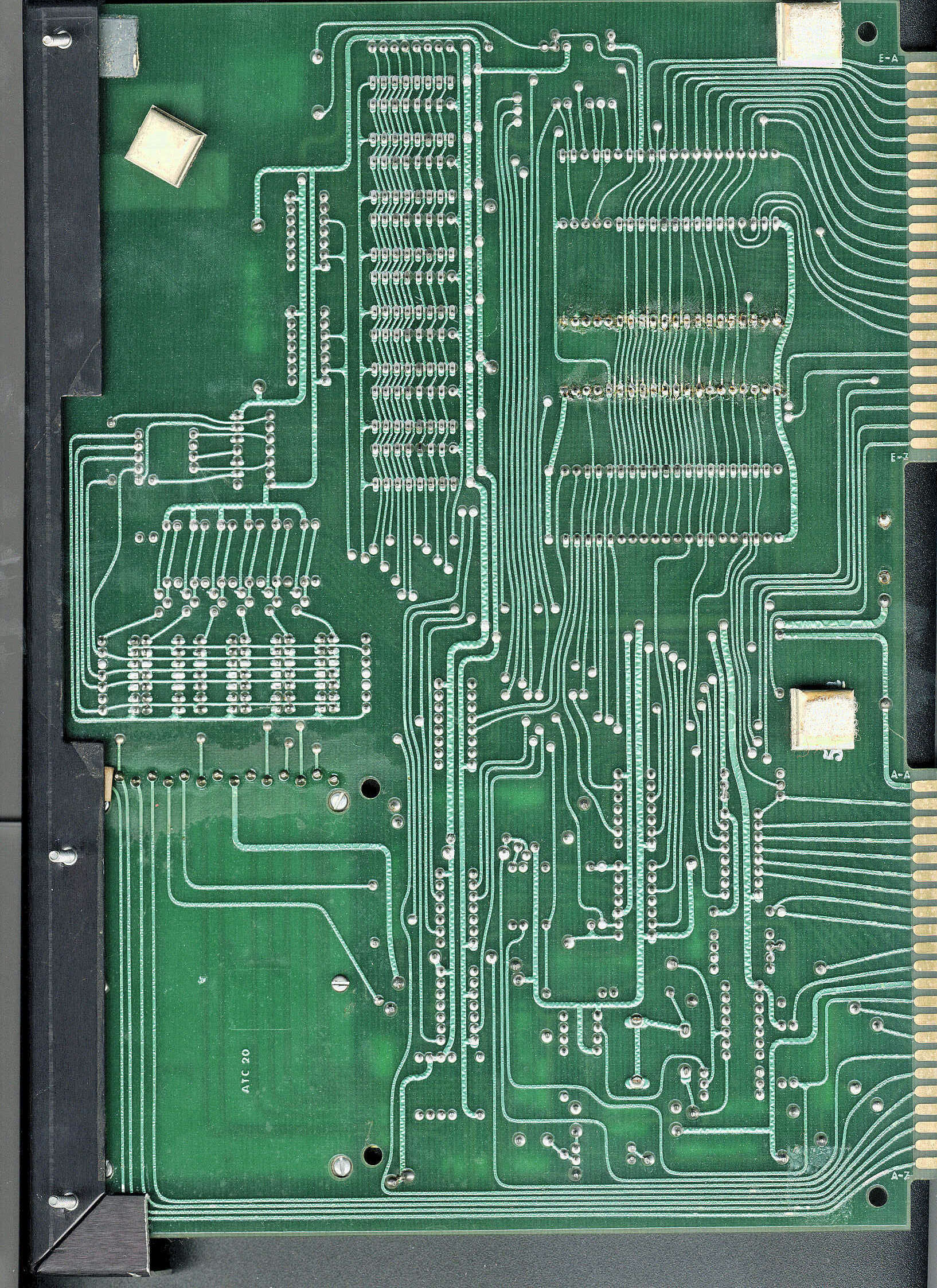
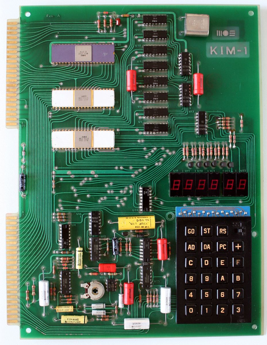
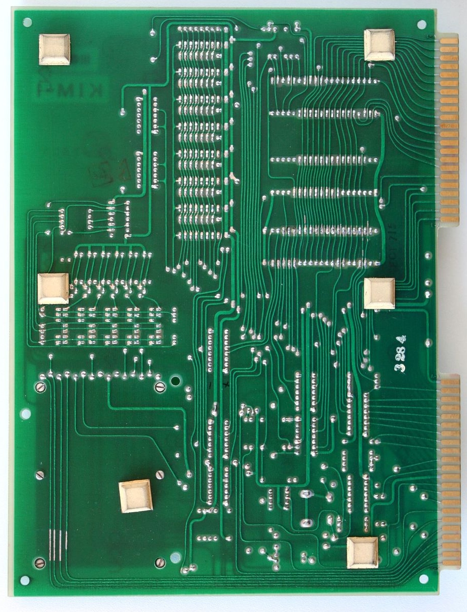
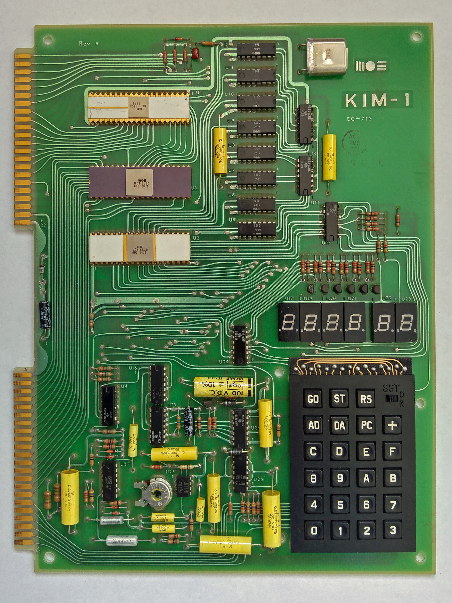
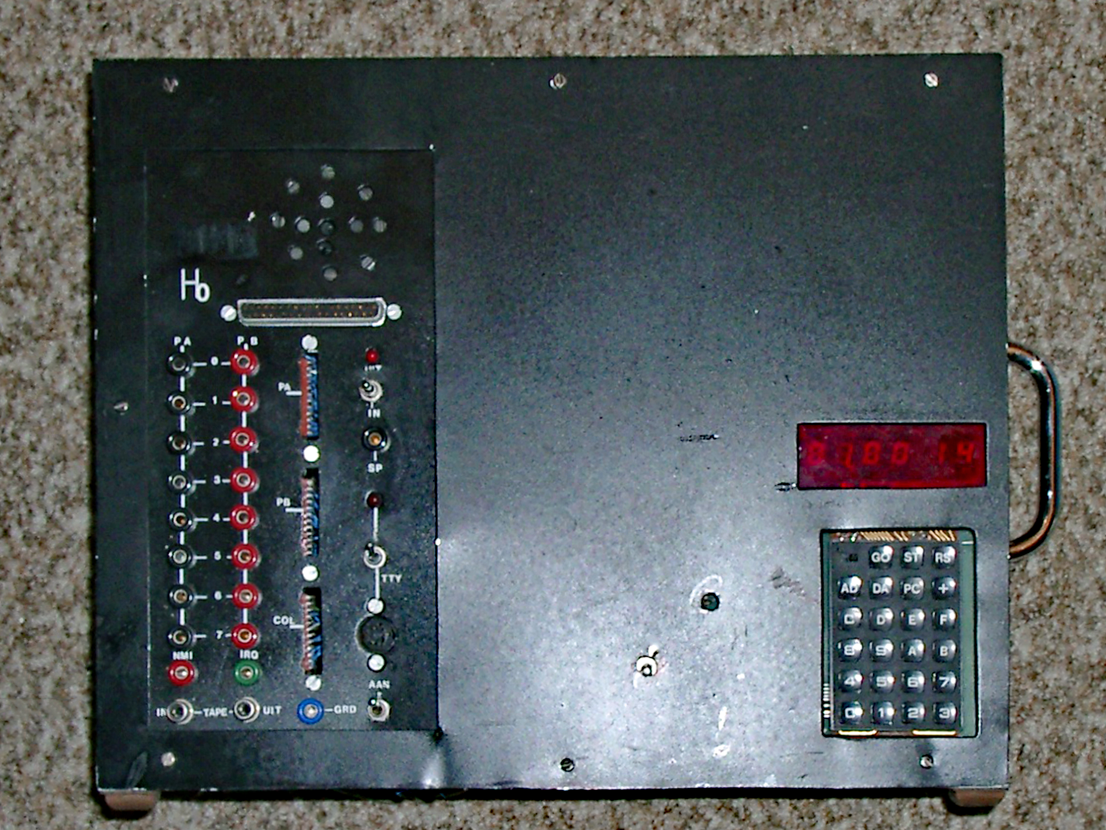
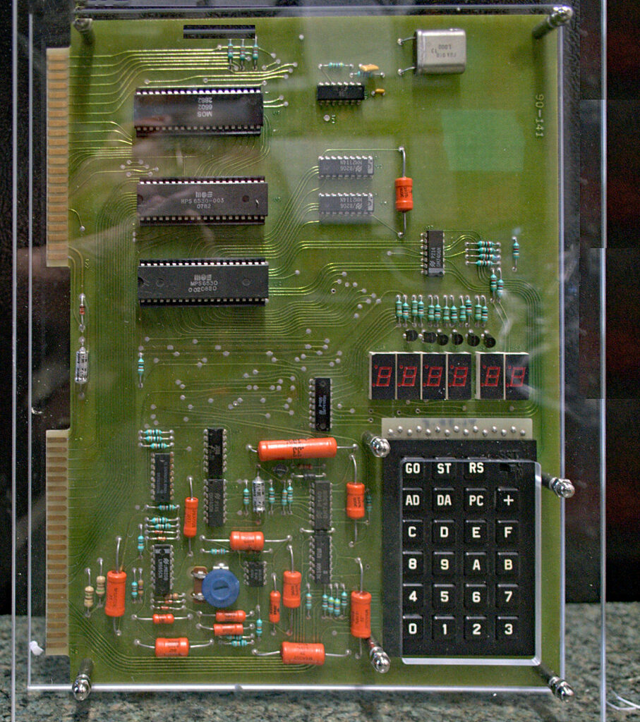
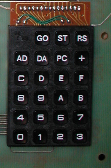
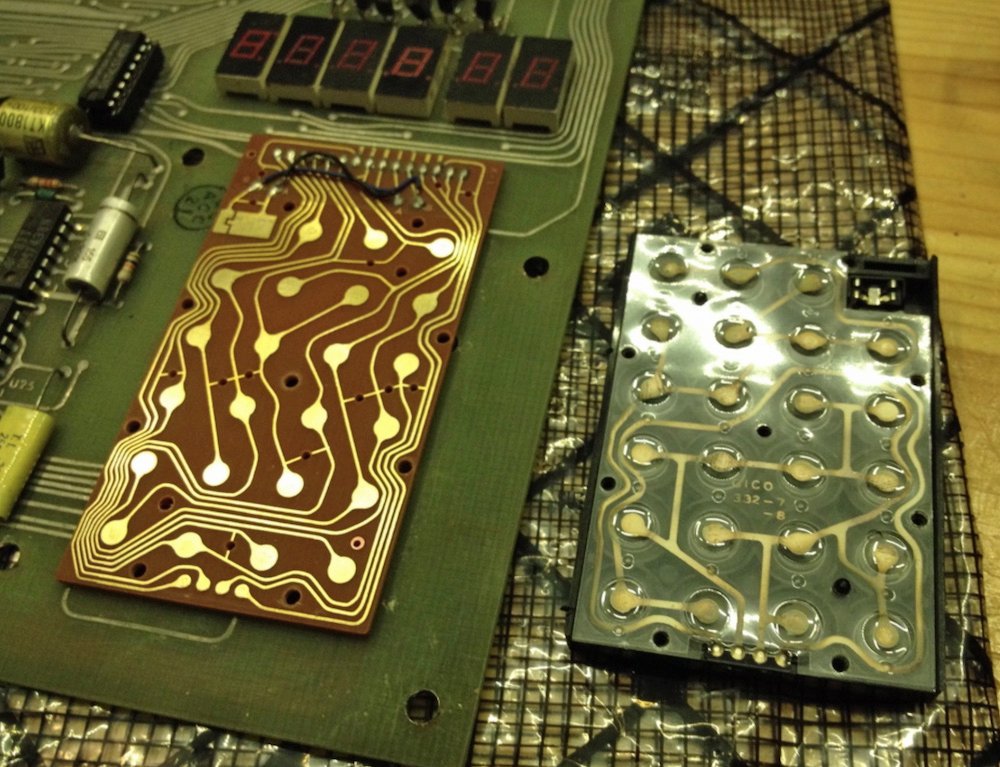
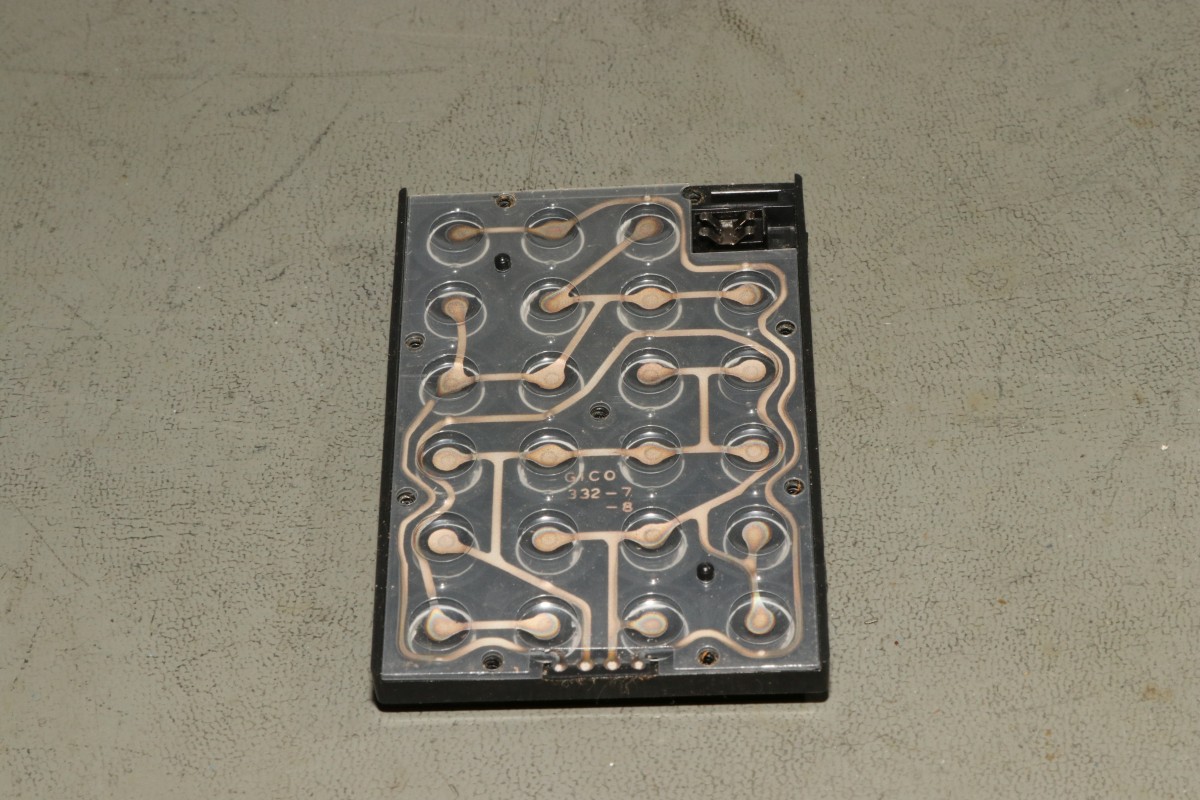
Decapped 6530-004 TIM photo’s by Frank Wolf
About small SBC systems
Decapped 6530-004 TIM photo’s by Frank Wolf
Didier form aida.org was approached by his friend Erik about a malfunctioning MPS-65.
By studying the material on this page and doing measurements on the board it was decided the PROM on the board was malfunctioning.
So Didier designed a GAL replacement for the PROM and the board came back to life!
Here the story how the design looks like.

A page on suppressing the KIM-1 echo of TTY input, read non-blocking and make the TTY input deaf.
Problems with the KIM-1 TTY character input
Here I present solutions for these problems in software, made possible by the genius hardware design of the KIM-1 TTY I/O.
Are they perfect? Maybe not, it is still bitbanging the incoming serial signal. It can miss the correct starting point for the incoming character bit stream.
If you want a perfect solution, you will need interrupt driven ringbuffered serial I/O with a dedicated IC like the 6850, 6551 etc.
Without this extra hardware you can achieve acceptable results with these routines.
Background in (updated) original article KIM Kenner 17 page 14, Dutch, Hans Otten, 1980
In the KIM Kenner 1 Siep de Vries, founder of the Dutch KIM Club mentioned how in Focal-65 for the 6502 a trick was built in to suppress the hardware echo by manipulating the TTY out bit PB0. I took the idea and implemented it on my KIM-1 in 1980 without seeing the Focal code, as I did not have a Focal binary yet then!
I examined in 2003 how it was done, from the Focal disassembly I made then:
34AF E6 76 L34AF INC $76 ; random number? 34B1 2C 40 17 BIT H1740 ; check if character is incoming 34B4 30 F9 BMI H34AF ;=> wait until startbit 34B6 AD 42 17 LDA H1742 34B9 29 FE AND #$FE ; clear PA7 34BB 8D 42 17 STA H1742 34BE 20 5A 1E JSR H1E5A ; KIM-1 input 34C1 48 PHA 34C2 AD 42 17 LDA H1742 34C5 29 FE AND #$FE ; isolate PA7 34C7 09 01 ORA #$01 ; set PA7 to 1 34C9 8D 42 17 STA H1742 34CC 68 PLA 34CD 18 CLC 34CE 60 RTS
The hardware echo of incoming serial signal to outgoing TTY output is shown in the next figures (from the KIM user manual and the KIM Circuit poster).
The TTY KEYBD signal goes via a transistor and NAND gate U15 to PA7 port of the 6532. That signal also goes to pin 10 input of NAND gate U26 which is the TTY out line. This is the hardware echo. When the KIM-1 sends out a character it comes from PB0 to pin 9 of of NAND gate U26 and so comes out to the TTY Out line.
PB5 (audio TTY control) is connected via an inverter to NAND gate U15. The other input is TTY IN. Making PB5 high will make the TTY input PA7 deaf for incoming signals.

The genius designers of the KIM-1 used NAND gates in the TTY I/O!
The KIM-1 GETCH routine detects an incoming character by looking in a loop for the start bit to appear. It then reads the character.
By first doing that loop of looking for the start bit and returning if not yet, then we have the check for a key pressed and a character coming in.
If a character is incoming we have to call as fast as possible the GETCH routine.
;
; KEYPRESS
; check character coming on character non-blocking
; - carry set if char coming in
; - follow up with GETCH or EGETCH as fast as possible if you want echo or no echo
;
KEYPRS LDA SAD
BMI NOKEY ; If bit 7 is set, the line is idle, no char
SEC
RTS ; Carry set if key pressed, A is key
NOKEY CLC
RTS ; carry clear, no key
As argued above, this is not foolproof. It is easy to miss an incoming character, as there is no buffering of the input.
The solution to suppress the echo is making output PB0 low. The NAND gate out will now stay high, ignoring any changes on the other input, the incoming serial character. So nothing is echoed.
In this routine the standard KIM-1 GETCH routine at $1E5A is encapsulated in a subroutine that prevents the echo by setting PB0. Note that this is not a complete block of the echo, it is only active when the program calls the blocking EGETCHAR. The calling program is now responsible for the echoing or otherwise.
;
; EGETCH from TTY without echo (Y returned FF due to GETCH)
;
EGETCH LDA SBD
AND #$FE ; Set PB0 to U26 low to suppress the echo
STA SBD
JSR GETCH
PHA
LDA SBD
ORA #$01 ; Set PB0 to U26 high to enable the echo
STA SBD
PLA
RTS
To make the TTY input really deaf you can use PB5. Calling the deaf routine hardware blocks any incoming TTY signal.
;
; TTYDEAF
; call this to block any incoming character
;
TTYDEAF LDA SBD
ORA #$20 ; Set PB5 to U26 high to block input
STA SBD
RTS
;
; TTYHEAR
; call this to restore incoming character via GETCH or EGETCH
;
TTYHEAR LDA SBD
AND #$DF ; Set PB5 to U26 low to allow input
STA SBD
RTS
Using TTYdeaf/hear in combination with KEYPRS and EGETCH works quite well to prevent most unwanted screen display of characters.
I wrote a litle program demonstarting the non-blocking and no echo facilities presented here.
Download sources, binary, papertape here.
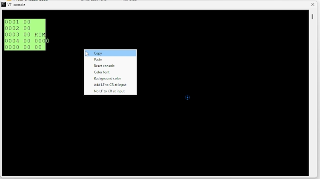
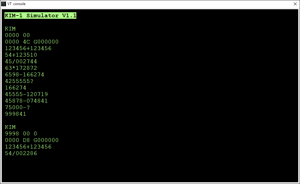
This is the console output of the program:
KIM 0000 0200 0200 A2 G Demo of echo suppress and non-blocking input Hans Otten, 2026 Normal get character, until ESCAPE 1 31 2 32 3 33 4 34 5 35 6 36 03 1B NOECHO get character, until ESCAPE 31 32 33 34 35 36 03 1B If run on KIM-1 Simulator: set in Settings Non-blocking or Focal-V3D Non-blocking no echo until ESCAPE 31 key pressed 32 key pressed 33 key pressed 03 key pressed Demo of echo suppress and non-blocking input Hans Otten, 2026 KIM 0200 A2 _
If you have a KIM-1, PAL-1, PAL-2 or Micro-KIM, these routines may help you.
The Corsham KIM Clone does not support PB5, and no deaf input on that one. Echo suppress works!
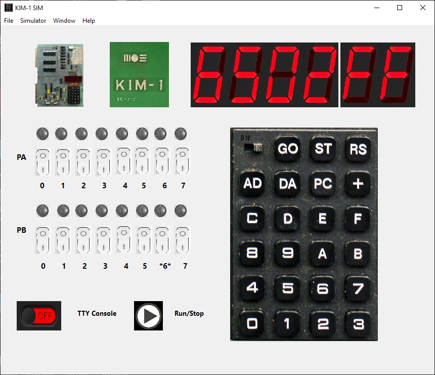
These routines also run on the KIM-1 Simulator. The non-blocking routine requires a Setting in the Simulator.
In versions before 2.3.1 check Focal-V3D, the later versions check Allow non-blocking.
The TTYdeaf routine does not work yet on the Simulator, PB5 is ignored.

Settings in 2.3.0

Settings 2.3.1
On the Utilities page I have two programs to convert to MOS Technology papertape format: KIMpaper, a command line utility, and ConvertHexFormat, a GUI app.
All in Freepascal/Lazarus source format, and tested on Linux (Raspberry PI OS) and Windows 10 64 bit. So the programs will run everywhere Lazarus is available (MS DOS, WIndows, Linux Mac OS).
KIMPAPER is written at the time the Micro-KIM appeared. CLI utility. Supports Binary to/from Papertape. Still runs fine on all platforms supported by Freepascal (Windows, MS DOS, Linux etc) after a recompilation, source available.
ConvertHexFormat is a more recent GUI utilitilty with many more 8 bit hex formats as input and output.
There were some bugs of course in older versions. V2 added the ability for multipart hex formats, records having a non-consecutive load address. That seems to wok fine since V2.1
In 2.2 a bug in MOS Papertape format for bigger files is fixed, the end-of-file record (record type 00, total line count) had a bug in the checksum calculation. KIMPAPER is and was correct in the calculation.
But in ConvertHexFormat it was wrong (as it still is in the well known srec utility in the Unix world!).
The PC utilities page has seen an update of th4 Conversion hex formats utility.
Programs to manipulate the binary and hex formatted files of interest for SBC owners. Intel hex, MOS papertape, Motorola S-record, binary, hex conversion fort eh 8 bit world.
Runs on Windows, Linux, Mac due to Lazarus and Freepascal. Source included.
The KIM-1 has two methods of loading programs:
– from audio files on the audio interface
– from papertape from a papertape reader connected to the teletype terminal
(Photos by Dave Wiliams with the MOS KIM-1 Reproduction)
The papertape method is the preferred way available for KIM-1 clone owners, since audio input input hardware is either not present or quite inconvenient and using terminal emulators is already the way we use these computers.
Now papertape format is a special MOS Technology format, already used in the TIM-1. See the KIM-1 user manual for a technical description.
This is for example the papertape output captured with the KIM-1 S command for the memory test program in the Fist Book of KIM
;1800000000A900A885FA8570A2028672A50085FBA601A57049FF850B27 ;1800187191FAC8D0FBE6FBE4FBB0F5A672A50085FBA570CA1004A20FF6 ;1800300291FAC8D0F6E6FBA501C5FBB0ECA50085FBA672A571CA100F73 ;18004804A202A570D1FAD015C8D0F0E6FBA501C5FBB0E8C67210AD0F29 ;0B0060A57049FF30A184FA4C4F1C05CE ;0000050005
Load address, data and checksums are in the records.
What the dump above does not show that the KIM-1 inserts in front of every record a series of NULL characters (a character with value 0), to give the papertape device time to do its mechnica work and also helps the slow KIM-1 load routine to do its work after a line end of a record.
A part of a real dump:

Papertape format is therefore a readable text file, but when captured from a KIM-1 output contains NULL characters.
So if we could send the papertape formatted test file to the KIM, we can load programs.
This requires solutions for the following:
Make a papertape file
The PC utilities section has programs to produce MOS papertape from binaries or other common 8 bit hex formats produced by assembler such as Intel hex, Motorola S-Record
Send a text file
Many terminal emulators that have support for serial allow to capture the serial output to a text file or send a text file to the serial input.
Good examples are nowadays Teraterm for Windows or Minicom for Linux.
Compensate for timing
The KIM-1 character routines are quite primitive and not rebust : bit-banged, not interrupt driven, no hardware ,handshake so no buffering and it is CPU intensive.
When you sent characters quite fast to the KIM-1 (and that means any baud rate from 1200 to 9600, and the KIM-1 also has to do some processing like processsing the record just received, it is to be expected the KIM-1 will be too late reading the next record, skip a record and sync at the next and leave the program received in chaso.
So we need to give time to the poor KIM-1.
1200 baud, 20 ms character delay, 200 ms line delay is conservative but reliable for me. It is slow ..
An example for Teraterm is shown here:

Decimal mode
The 6502 NMOS version is in unknown state after reset regarding decimal mode.
Most programs start with the CLD D8 instruction, but not all. Microsoft KIM-1 Basic v1.1 is one of those.
A section from the KIM Hints:
A number of KIM-1 customers have reported difficulty in achieving correct results for the sample problem shown in Sec. 2.4 of the KIM-1 User Manual. In addition, some customers have experienced problems in recording or playback of audio cassettes. (Sec. 2.5 of the KIM-1 User Manual). In all cases, the problems have been traced to a single cause: the inadvertent setting of the DECIMAL MODE.
The 6502 Microprocessor Array used in the KIM-1 system is capable of operating in either binary or decimal arithmetic mode. The programmer must be certain that the mode is selected correctly for the program to be executed. Since the system may be in either mode after initial power-on, a specific action is required to insure the selection of the correct mode. Specifically, the results predicted for the sample problem (Sec. 2.4) are based on the assumption that the system is operating in the binary arithmetic mode. To insure that this is the case, insert the following key sequence prior to the key operations shown at the bottom of Page 11 of the KIM-1 User Manual.
[AD]
[0] [0] [F] [1]
[DA] [0] [0]
This sequence resets the decimal mode flag in the Status Register prior to the execution of the sample program.
The same key sequence may be inserted prior to the key operations shown on pages 14 and 15 for audio cassette recording and playback. These operations will not be performed correctly if the decimal mode is in effect.
In general, whenever a program is to be executed in response to the [GO] key, the programmer should insure that the correct arithmetic mode has been set in the status register (00F1) prior to program execution.
A 6502, 65C02, 65816 assembler and simulator. Original (with Polish help) by Michal Kowalski, 65816 extensions with English help by Daryl Rictor.
A nice tool to develop and test 65XX software.
Read here to get it, install and some startup help.
Michael Kowalski created the 6502 Simulator many years ago. It simulated the MOS 6502, CMOS 65C02, and the 6501. Daryl Rictor took the sources and updated with 65816 assembler and emulator support to 16MB memory. He also translated the Polish help to English in CHM format. It is a Windows 32 bit program and runs fine on Windows 10 64 bit.
The debugger/simulator is still only 65(C)02.
The latest version by Michal Kowalski is here.

You can write code, assemble it, and run it with a debugger with breakpoints, step by step etcetera.
Entering the source code
Open a blank source file by clicking on (File / New)
Type in your assembly language program
Save it by doing (File / Save as). Use the suggested extension of .65s for your filename.
Assembling the source code
Assemble the source code by clicking on (Simulator / Assemble).
If there are any errors in your code, an error message should come up at this point.
Using the debugger
Turn on the debugger by clicking on (Simulator / Debugger), or press F6.
Go to the View menu and make the following windows visible:
– 6502 Registers
– 6502 Memory
– Identifiers
Find the assembled machine code in the Memory window. It should match up with the codes on the handout.
A better way of looking at the code is to open the Disassembler window ( View / Disassembler ) which shows you clearly which instructions produced which machine code bytes.
The identifiers window tells you which memory locations have been set aside for the variables that you declared at the bottom of your program. That is all it is for really, so once you have seen that, you can close it.
Running the program
To run the program you have various options, all listed on the Simulator menu. The most useful one from a teaching point of view is ( Simulator / Step Into) or F11.
Arrange your windows so that you can see the source code, the memory window, and the registers window ( and the Dissassembler window if you want) and use F11 to start to step through the code.
After each instruction, look at the state of the registers, and satisfy yourself that the instruction has done what you expected it to. Also, when you do a Store to Memory instruction, you should see the value pop up in the appropriate place in the memory window.
When you have finished running the program, click on (Simulator / Restart Program) before trying to run it again.
In the file parse6502.cpp in the subfolder CrystalEdit you can read some assemble directives and I/O ports not documented in the Help.
Some are not documented in the Help but are in the sourcefile crytaledit/Parse6502.cpp
.ASCII
Directives defining values of single bytes using passed arguments.
Syntax
[
Example
alpha: .DB \”ABC\”, 0 ; generates bytes ‘A’, ‘B’, ‘C’, 0
beta: .DB %1, %1$ ; macro params; string length and string itself
.BYTE <[alpha-1], >[alpha-1]”
.ASCII \”Text\”
Description
.BYTE (.DB, .ASCII) directives generates and defines single byte values. Input data might be entered in numerical or string form. Numerical expressions are also accepted.
.ROM_AREA
Directive establishing memory protection area
Syntax
.ROM_AREA addr_from_expr, addr_to_expr
Example
.ROM_AREA $a000, $afff
.ROM_AREA Start, * ; from ‘Start’ to here
Description
.ROM_AREA turns on memory protection for a given range of addresses. Any attempt to write to this area will stop program execution. Write attempts to the EPROM usually indicate a bug and memory protection can facilitate locating such bugs. Specifying same start and end address turns protection off
.IO_WND
Directive setting terminal window size.
Syntax
.IO_WND cols_expr, rows_expr
Example
.IO_WND 40, 20; 40 columns, 20 rows
Description
.IO_WND directive sets size of terminal window. It requires two parameters: number of columns and rows.
Both columns and rows are limited to 1..255 range.
IO_AREA
Label representing beginning of simulator I/O area.
Syntax
IO_AREA = addr_expr ; set I/O area
Example
IO_CLS = IO_AREA + 0 ; clear window port
STA IO_AREA+1 ; put char
Description
IO_AREA label represents beginning of simulator I/O area. Simulator can detect read and write attempts
from/to its I/O area.
Starting from IO_AREA address consecutive bytes are treated as virtual ports.”
Following ports are defined:
IO_AREA+0: TERMINAL_CLS (w)
IO_AREA+1: TERMINAL_OUT (w)
IO_AREA+2: TERMINAL_OUT_CHR (w)
IO_AREA+3: TERMINAL_OUT_HEX (w)
IO_AREA+4: TERMINAL_IN (r)
IO_AREA+5: TERMINAL_X_POS (r/w)
IO_AREA+6: TERMINAL_Y_POS (r/w)
(w) means write only port, (r) read only, (r/w) read/write.
TERMINAL_CLS – clear terminal window, set cursor at (0,0) position
TERMINAL_OUT – output single character interpreting control characters.
Terminal can only recognize those characters:
– $d char (caret) moving cursor to the beginning of line,
– $a char (line feed) moving cursor to the next line and scrolling window if necessary,
– 8 char (backspace) moving one position to the left and erasing char below cursor.
TERMINAL_OUT_CHR – outputs single character; control chars are being output just like regular characters.
TERMINAL_OUT_HEX – outputs single byte as a two-digit hexadecimal number.
TERMINAL_IN – input single byte, returns 0 if there’s no characters available in terminal’s buffer
– when I/O terminal window is active it can accept keyboard input;
– press Ins key to paste clipboard’s contents into terminal.
TERMINAL_X_POS – cursor X position (column).
TERMINAL_Y_POS – cursor Y position (row).
The Kowalski simulator includes a primitive I/O console, which is memory-mapped at a location declared with the IO_AREA pseudo-op. For example, IO_AREA=$D000 will map the console in at $D000.
From the sample archive (download archive here)
; Wait for input test ; IO area of the simulator has to be set at the address $e000 ; (Option/Simulator/InOut memory area) ; In/Out Window will only accept input when it has focus (is active) *= $0600 io_area = $e000 io_cls = io_area + 0 ; clear terminal window io_putc = io_area + 1 ; put char io_putr = io_area + 2 ; put raw char (doesn't interpret CR/LF) io_puth = io_area + 3 ; put as hex number io_getc = io_area + 4 ; get char LDA #$a STA io_putc ; this will move cursor to the next line STA io_putr ; this will print character LDA #'>' STA io_putc .wait LDA io_getc BEQ .wait STA io_puth JMP .wait BRK
Compared to 6502 and 65C02 microprocessors, the simulator is characterized by the following different components:
With the simulator you can run a program assembled from the built-in editor. Or you can load an Intel Hex file, a Motorola S-record file or a binary file. The type is determined by the extension, so you may have to rename your hex files. The simulator makes all memory available, only the IO_AREA is special.
Several Windows Can be opened during a debug session: Processor Status and registers, Memory, Disassembly, Text Input/output, Stack, ZeroPage, Identifiers (from assembled symbol table)

A good example of a Kowalski program is the source of Lee Davison’a EhBasic Minimal Monitor
; minimal monitor for EhBASIC and 6502 simulator V1.05 ; To run EhBASIC on the simulator load and assemble [F7] this file, start the simulator ; running [F6] then start the code with the RESET [CTRL][SHIFT]R. Just selecting RUN ; will do nothing, you'll still have to do a reset to run the code. .include "basic.asm" ; put the IRQ and MNI code in RAM so that it can be changed IRQ_vec = VEC_SV+2 ; IRQ code vector NMI_vec = IRQ_vec+$0A ; NMI code vector ; setup for the 6502 simulator environment IO_AREA = $F000 ; set I/O area for this monitor ACIAsimwr = IO_AREA+$01 ; simulated ACIA write port ACIAsimrd = IO_AREA+$04 ; simulated ACIA read port ; now the code. all this does is set up the vectors and interrupt code ; and wait for the user to select [C]old or [W]arm start. nothing else ; fits in less than 128 bytes *= $FF80 ; pretend this is in a 1/8K ROM ; reset vector points here RES_vec CLD ; clear decimal mode LDX #$FF ; empty stack TXS ; set the stack ; set up vectors and interrupt code, copy them to page 2 LDY #END_CODE-LAB_vec ; set index/count LAB_stlp LDA LAB_vec-1,Y ; get byte from interrupt code STA VEC_IN-1,Y ; save to RAM DEY ; decrement index/count BNE LAB_stlp ; loop if more to do ; now do the signon message, Y = $00 here LAB_signon LDA LAB_mess,Y ; get byte from sign on message BEQ LAB_nokey ; exit loop if done JSR V_OUTP ; output character INY ; increment index BNE LAB_signon ; loop, branch always LAB_nokey JSR V_INPT ; call scan input device BCC LAB_nokey ; loop if no key AND #$DF ; mask xx0x xxxx, ensure upper case CMP #'W' ; compare with [W]arm start BEQ LAB_dowarm ; branch if [W]arm start CMP #'C' ; compare with [C]old start BNE RES_vec ; loop if not [C]old start JMP LAB_COLD ; do EhBASIC cold start LAB_dowarm JMP LAB_WARM ; do EhBASIC warm start ; byte out to simulated ACIA ACIAout STA ACIAsimwr ; save byte to simulated ACIA RTS ; byte in from simulated ACIA ACIAin LDA ACIAsimrd ; get byte from simulated ACIA BEQ LAB_nobyw ; branch if no byte waiting SEC ; flag byte received RTS LAB_nobyw CLC ; flag no byte received no_load ; empty load vector for EhBASIC no_save ; empty save vector for EhBASIC RTS ; vector tables LAB_vec .word ACIAin ; byte in from simulated ACIA .word ACIAout ; byte out to simulated ACIA .word no_load ; null load vector for EhBASIC .word no_save ; null save vector for EhBASIC ; EhBASIC IRQ support IRQ_CODE PHA ; save A LDA IrqBase ; get the IRQ flag byte LSR ; shift the set b7 to b6, and on down ... ORA IrqBase ; OR the original back in STA IrqBase ; save the new IRQ flag byte PLA ; restore A RTI ; EhBASIC NMI support NMI_CODE PHA ; save A LDA NmiBase ; get the NMI flag byte LSR ; shift the set b7 to b6, and on down ... ORA NmiBase ; OR the original back in STA NmiBase ; save the new NMI flag byte PLA ; restore A RTI END_CODE LAB_mess .byte $0D,$0A,"6502 EhBASIC [C]old/[W]arm ?",$00 ; sign on string ; system vectors *= $FFFA .word NMI_vec ; NMI vector .word RES_vec ; RESET vector .word IRQ_vec ; IRQ vector
KOWALSKI ASSEMBLER LOGICAL, BITWISE & ARITHMETIC OPERATORS
.opt proc65c02,caseinsensitive ;KOWALSKI ASSEMBLER LOGICAL, BITWISE & ARITHMETIC OPERATORS ; ; ; number radices... ; ; @ binary, e.g., @01011010 ; $ hex, e.g., $5a ; none decimal ; test0001 =@00001111 test0002 =test0001 << 4 ;logical shift left 4 bits test0003 =test0002 >> 4 ;logical shift right 4 bits test0004 =test0001 & test0002 ;bitwise AND test0005 =test0001 | test0002 ;bitwise OR test0006 =test0001 && test0002 ;logical AND test0007 =test0001 || test0002 ;logical OR test0008 =!0 ;bitwise NOT test0009 =$5a ^ test0005 ;bitwise XOR test0010 =4 == 3 ;equality test test0011 =4 == 4 ;equality test test0012 =4 != 3 ;inequality test test0013 =4 != 4 ;inequality test test0014 =4 > 3 ;greater-than test test0015 =4 < 3 ;lesser-than test test0016 =~1 ;2s complement ; ; ; arithmetic operators... ; ; + addition ; - subtraction ; * multiplication ; / division ; % modulo ; sum = 5 + 6 ;evaluates to 11 diff = sum - 6 ;evaluates to 5 prod = 5 * 6 ;evaluates to 30 quot =prod / diff ;evaluates to 6 mod =prod % sum ;evaluates to 8 ; ; ; example using square brackets to alter evaluation precedence... ; test0017 =5 + 6 * 2 ;strictly left-to-right: evaluates to 17 test0018 =[5 + 6] * 2 ;sum of 5 & 6 computed 1st: evaluates to 22 ; .end
Assembler test, all opcodes 65C02
; .title 6500 Assembler Test dir .= $0033 ext .= $1122 offset .= $0044 extext .= 0 extdir .= 0 r65f11 .= 1 r65c00 .= 1 r65c02 .= 1 .OPT Proc65c02 ; ; All documented 650X, 651X, 65F11, 65F12, 65C00/21, 65C29, ; 65C02, 65C102, and 65C112 instructions with proper AS6500 syntax. ; .org $1000 adc #12 ;69 12 ;--- adc 1234 ;6D 34 12 adc ext ;6D 22 11 adc extext ;6Du00v00 ;--- adc 12 ;65 12 adc dir ;65 33 adc extext ;65 00 ;--- adc 12,x ;75 12 adc dir,x ;75 33 adc offset,x ;75 44 adc extdir,x ;75 00 ;--- adc 1234,x ;7D 34 12 adc ext,x ;7D 22 11 adc extext,x ;7Du00v00 ;--- adc 1234,y ;79 34 12 adc dir,y ;79 33 00 adc extdir,y ;79u00v00 adc ext,y ;79 22 11 adc extext,y ;79u00v00 ;--- adc (12,x) ;61 12 adc ( dir,x) ;61 33 adc (offset,x) ;61 44 adc ( extdir,x) ;61 00 adc (extext,x) ;61 00 ;--- adc (12),y ;71 12 adc ( dir),y ;71 33 adc (offset),y ;71 44 adc ( extdir),y ;71 00 adc (extext),y ;71 00 ;--- .if r65c02 adc (12) ;72 12 adc ( dir) ;72 33 adc (offset) ;72 44 adc ( extdir) ;72 00 adc (extext) ;72 00 .endif and #12 ;29 12 ;--- and 1234 ;2D 34 12 and ext ;2D 22 11 and extext ;2Du00v00 ;--- and 12 ;25 12 and dir ;25 33 and extext ;25 00 ;--- and 12,x ;35 12 and dir,x ;35 33 and offset,x ;35 44 and extdir,x ;35 00 ;--- and 1234,x ;3D 34 12 and ext,x ;3D 22 11 and extext,x ;3Du00v00 ;--- and 1234,y ;39 34 12 and dir,y ;39 33 00 and extdir,y ;39u00v00 and ext,y ;39 22 11 and extext,y ;39u00v00 ;--- and (12,x) ;21 12 and ( dir,x) ;21 33 and (offset,x) ;21 44 and ( extdir,x) ;21 00 and (extext,x) ;21 00 ;--- and (12),y ;31 12 and ( dir),y ;31 33 and (offset),y ;31 44 and ( extdir),y ;31 00 and (extext),y ;31 00 ;--- .if r65c02 and (12) ;32 12 and ( dir) ;32 33 and (offset) ;32 44 and ( extdir) ;32 00 and (extext) ;32 00 .endif ; asl a ;0A asl ;0A ;--- asl 1234 ;0E 34 12 asl ext ;0E 22 11 asl extext ;0Eu00v00 ;--- asl 12 ;06 12 asl dir ;06 33 asl extext ;06 00 ;--- asl 12,x ;16 12 asl dir,x ;16 33 asl offset,x ;16 44 asl extdir,x ;16 00 ;--- asl 1234,x ;1E 34 12 asl ext,x ;1E 22 11 asl extext,x ;1Eu00v00 .if r65f11+r65c00+r65c02 bbr#0,12,* ;0F 12 FD bbr#1, 12,* ;1F 12 FD bbr#2, 12,* ;2F 12 FD bbr#3, 12,* ;3F 12 FD bbr#4, 12,* ;4F 12 FD bbr#5, 12,* ;5F 12 FD bbr#6, 12,* ;6F 12 FD bbr#7, 12,* ;7F 12 FD bbs#0, 12,* ;8F 12 FD bbs#1, 12,* ;9F 12 FD bbs#2, 12,* ;AF 12 FD bbs#3, 12,* ;BF 12 FD bbs#4, 12,* ;CF 12 FD bbs#5, 12,* ;DF 12 FD bbs#6, 12,* ;EF 12 FD bbs#7, 12,* ;FF 12 FD .1: bbr #0, 12,.3 ;0F 12 03 .2: bbr #0, dir,.2 ;0F 33 FD .3: bbr #0, extext,.1 ;0F 00 F7 .4: bbs #0, 12,.6 ;8F 12 03 .5: bbs #0, dir,.5 ;8F 33 FD .6: bbs #0, extext,.4 ;8F 00 F7 .endif bcc * ;90 FE bcs * ;B0 FE beq * ;F0 FE .if r65c02 bit #12 ;89 12 .endif ;--- bit 1234 ;2C 34 12 bit ext ;2C 22 11 bit extext ;2Cu00v00 ;--- bit 12 ;24 12 bit dir ;24 33 bit extext ;24 00 ;--- .if r65c02 bit 12,x ;34 12 bit dir,x ;34 33 bit offset,x ;34 44 bit extdir,x ;34 00 ;--- bit 1234,x ;3C 34 12 bit ext,x ;3C 22 11 bit extext,x ;3Cu00v00 .endif bmi * ;30 FE bne * ;D0 FE bpl * ;10 FE .if r65c00+r65c02 bra * ;80 FE .endif brk ;00 bvc * ;50 FE bvs * ;70 FE clc ;18 cld ;D8 cli ;58 clv ;B8 cmp #12 ;C9 12 ;--- cmp 1234 ;CD 34 12 cmp ext ;CD 22 11 cmp extext ;CDu00v00 ;--- cmp 12 ;C5 12 cmp dir ;C5 33 cmp extext ;C5 00 ;--- cmp 12,x ;D5 12 cmp dir,x ;D5 33 cmp offset,x ;D5 44 cmp extdir,x ;D5 00 ;--- cmp 1234,x ;DD 34 12 cmp ext,x ;DD 22 11 cmp extext,x ;DDu00v00 ;--- cmp 1234,y ;D9 34 12 cmp dir,y ;D9 33 00 cmp extdir,y ;D9u00v00 cmp ext,y ;D9 22 11 cmp extext,y ;D9u00v00 ;--- cmp (12,x) ;C1 12 cmp ( dir,x) ;C1 33 cmp (offset,x) ;C1 44 cmp ( extdir,x) ;C1 00 cmp (extext,x) ;C1 00 ;--- cmp (12),y ;D1 12 cmp ( dir),y ;D1 33 cmp (offset),y ;D1 44 cmp ( extdir),y ;D1 00 cmp (extext),y ;D1 00 ;--- .if r65c02 cmp (12) ;D2 12 cmp ( dir) ;D2 33 cmp (offset) ;D2 44 cmp ( extdir) ;D2 00 cmp (extext) ;D2 00 .endif .if r65c02 cpx #12 ;E0 12 .endif ;--- cpx 12 ;E4 12 cpx dir ;E4 33 cpx extdir ;E4 00 ;--- cpx 1234 ;EC 34 12 cpx ext ;EC 22 11 cpx extext ;ECu00v00 .if r65c02 cpy #12 ;C0 12 .endif ;--- cpy 12 ;C4 12 cpy dir ;C4 33 cpy extdir ;C4 00 ;--- cpy 1234 ;CC 34 12 cpy ext ;CC 22 11 cpy extext ;CCu00v00 .if r65c02 ; dec a ;3A dea ;3A .endif ;--- dec 1234 ;CE 34 12 dec ext ;CE 22 11 dec extext ;CEu00v00 ;--- dec 12 ;C6 12 dec dir ;C6 33 dec extext ;C6 00 ;--- dec 12,x ;D6 12 dec dir,x ;D6 33 dec offset,x ;D6 44 dec extdir,x ;D6 00 ;--- dec 1234,x ;DE 34 12 dec ext,x ;DE 22 11 dec extext,x ;DEu00v00 dex ;CA dey ;88 eor #12 ;49 12 ;--- eor 1234 ;4D 34 12 eor ext ;4D 22 11 eor extext ;4Du00v00 ;--- eor 12 ;45 12 eor dir ;45 33 eor extext ;45 00 ;--- eor 12,x ;55 12 eor dir,x ;55 33 eor offset,x ;55 44 eor extdir,x ;55 00 ;--- eor 1234,x ;5D 34 12 eor ext,x ;5D 22 11 eor extext,x ;5Du00v00 ;--- eor 1234,y ;59 34 12 eor dir,y ;59 33 00 eor extdir,y ;59u00v00 eor ext,y ;59 22 11 eor extext,y ;59u00v00 ;--- eor (12,x) ;41 12 eor ( dir,x) ;41 33 eor (offset,x) ;41 44 eor ( extdir,x) ;41 00 eor (extext,x) ;41 00 ;--- eor (12),y ;51 12 eor ( dir),y ;51 33 eor (offset),y ;51 44 eor ( extdir),y ;51 00 eor (extext),y ;51 00 ;--- .if r65c02 eor (12) ;52 12 eor ( dir) ;52 33 eor (offset) ;52 44 eor ( extdir) ;52 00 eor (extext) ;52 00 .endif .if r65c02 ; inc a ;1A ina ;1A .endif ;--- inc 1234 ;EE 34 12 inc ext ;EE 22 11 inc extext ;EEu00v00 ;--- inc 12 ;E6 12 inc dir ;E6 33 inc extext ;E6 00 ;--- inc 12,x ;F6 12 inc dir,x ;F6 33 inc offset,x ;F6 44 inc extdir,x ;F6 00 ;--- inc 1234,x ;FE 34 12 inc ext,x ;FE 22 11 inc extext,x ;FEu00v00 inx ;E8 iny ;C8 jmp 12 ;4C 12 00 jmp dir ;4C 33 00 jmp extext ;4Cu00v00 ;--- jmp 1234 ;4C 34 12 jmp ext ;4C 22 11 jmp extext ;4Cu00v00 ;--- jmp (1234) ;6C 34 12 jmp (ext) ;6C 22 11 jmp (extext) ;6Cu00v00 ;--- .if r65c02 jmp (1234,x) ;7C 34 12 jmp (ext,x) ;7C 22 11 ; jmp (extext,x) ;7Cu00v00 .endif jsr dir ;20 33 00 jsr extdir ;20u00v00 ;--- jsr 1234 ;20 34 12 jsr ext ;20 22 11 jsr extext ;20u00v00 lda #12 ;A9 12 ;--- lda 1234 ;AD 34 12 lda ext ;AD 22 11 lda extext ;ADu00v00 ;--- lda 12 ;A5 12 lda dir ;A5 33 lda extext ;A5 00 ;--- lda 12,x ;B5 12 lda dir,x ;B5 33 lda offset,x ;B5 44 lda extdir,x ;B5 00 ;--- lda 1234,x ;BD 34 12 lda ext,x ;BD 22 11 lda extext,x ;BDu00v00 ;--- lda 1234,y ;B9 34 12 lda dir,y ;B9 33 00 lda extdir,y ;B9u00v00 lda ext,y ;B9 22 11 lda extext,y ;B9u00v00 ;--- lda (12,x) ;A1 12 lda ( dir,x) ;A1 33 lda (offset,x) ;A1 44 lda ( extdir,x) ;A1 00 lda (extext,x) ;A1 00 ;--- lda (12),y ;B1 12 lda ( dir),y ;B1 33 lda (offset),y ;B1 44 lda ( extdir),y ;B1 00 lda (extext),y ;B1 00 ;--- .if r65c02 lda (12) ;B2 12 lda ( dir) ;B2 33 lda (offset) ;B2 44 lda ( extdir) ;B2 00 lda (extext) ;B2 00 .endif ldx #12 ;A2 12 ;--- ldx 12 ;A6 12 ldx dir ;A6 33 ldx extdir ;A6 00 ;--- ldx 12,y ;B6 12 ldx dir,y ;B6 33 ldx extdir,y ;B6 00 ;--- ldx 1234 ;AE 34 12 ldx ext ;AE 22 11 ldx extext ;AEu00v00 ;--- ldx 1234,y ;BE 34 12 ldx ext,y ;BE 22 11 ldx extext,y ;BEu00v00 ldy #12 ;A0 12 ;--- ldy 12 ;A4 12 ldy dir ;A4 33 ldy extdir ;A4 00 ;--- ldy 12,x ;B4 12 ldy dir,x ;B4 33 ldy extdir,x ;B4 00 ;--- ldy 1234 ;AC 34 12 ldy ext ;AC 22 11 ldy extext ;ACu00v00 ;--- ldy 1234,x ;BC 34 12 ldy ext,x ;BC 22 11 ldy extext,x ;BCu00v00 ; lsr a ;4A lsr ;4A ;--- lsr 1234 ;4E 34 12 lsr ext ;4E 22 11 lsr extext ;4Eu00v00 ;--- lsr 12 ;46 12 lsr dir ;46 33 lsr extext ;46 00 ;--- lsr 12,x ;56 12 lsr dir,x ;56 33 lsr offset,x ;56 44 lsr extdir,x ;56 00 ;--- lsr 1234,x ;5E 34 12 lsr ext,x ;5E 22 11 lsr extext,x ;5Eu00v00 .if r65c00 ; mul ;02 .endif nop ;EA ora #12 ;09 12 ;--- ora 1234 ;0D 34 12 ora ext ;0D 22 11 ora extext ;0Du00v00 ;--- ora 12 ;05 12 ora dir ;05 33 ora extext ;05 00 ;--- ora 12,x ;15 12 ora dir,x ;15 33 ora offset,x ;15 44 ora extdir,x ;15 00 ;--- ora 1234,x ;1D 34 12 ora ext,x ;1D 22 11 ora extext,x ;1Du00v00 ;--- ora 1234,y ;19 34 12 ora dir,y ;19 33 00 ora extdir,y ;19u00v00 ora ext,y ;19 22 11 ora extext,y ;19u00v00 ;--- ora (12,x) ;01 12 ora ( dir,x) ;01 33 ora (offset,x) ;01 44 ora ( extdir,x) ;01 00 ora (extext,x) ;01 00 ;--- ora (12),y ;11 12 ora ( dir),y ;11 33 ora (offset),y ;11 44 ora ( extdir),y ;11 00 ora (extext),y ;11 00 ;--- .if r65c02 ora (12) ;12 12 ora ( dir) ;12 33 ora (offset) ;12 44 ora ( extdir) ;12 00 ora (extext) ;12 00 .endif pha ;48 php ;08 .if r65c00+r65c02 phx ;DA phy ;5A .endif pla ;68 plp ;28 .if r65c00+r65c02 plx ;FA ply ;7A .endif .if r65f11+r65c00+r65c02 rmb #0, 12 ;07 12 rmb #1, 12 ;17 12 rmb #2, 12 ;27 12 rmb #3, 12 ;37 12 rmb #4, 12 ;47 12 rmb #5, 12 ;57 12 rmb #6, 12 ;67 12 rmb #7, 12 ;77 12 rmb #0, dir ;07 33 rmb #0, extdir ;07 00 .endif .if r65c02 ; rol a ;2A rol ;2A .endif ;--- rol 1234 ;2E 34 12 rol ext ;2E 22 11 rol extext ;2Eu00v00 ;--- rol 12 ;26 12 rol dir ;26 33 rol extext ;26 00 ;--- rol 12,x ;36 12 rol dir,x ;36 33 rol offset,x ;36 44 rol extdir,x ;36 00 ;--- rol 1234,x ;3E 34 12 rol ext,x ;3E 22 11 rol extext,x ;3Eu00v00 ; ror a ;6A ror ;6A ;--- ror 1234 ;6E 34 12 ror ext ;6E 22 11 ror extext ;6Eu00v00 ;--- ror 12 ;66 12 ror dir ;66 33 ror extext ;66 00 ;--- ror 12,x ;76 12 ror dir,x ;76 33 ror offset,x ;76 44 ror extdir,x ;76 00 ;--- ror 1234,x ;7E 34 12 ror ext,x ;7E 22 11 ror extext,x ;7Eu00v00 rti ;40 rts ;60 sbc #12 ;E9 12 ;--- sbc 1234 ;ED 34 12 sbc ext ;ED 22 11 sbc extext ;EDu00v00 ;--- sbc 12 ;E5 12 sbc dir ;E5 33 sbc extext ;E5 00 ;--- sbc 12,x ;F5 12 sbc dir,x ;F5 33 sbc offset,x ;F5 44 sbc extdir,x ;F5 00 ;--- sbc 1234,x ;FD 34 12 sbc ext,x ;FD 22 11 sbc extext,x ;FDu00v00 ;--- sbc 1234,y ;F9 34 12 sbc dir,y ;F9 33 00 sbc extdir,y ;F9u00v00 sbc ext,y ;F9 22 11 sbc extext,y ;F9u00v00 ;--- sbc (12,x) ;E1 12 sbc ( dir,x) ;E1 33 sbc (offset,x) ;E1 44 sbc ( extdir,x) ;E1 00 sbc (extext,x) ;E1 00 ;--- sbc (12),y ;F1 12 sbc ( dir),y ;F1 33 sbc (offset),y ;F1 44 sbc ( extdir),y ;F1 00 sbc (extext),y ;F1 00 ;--- .if r65c02 sbc (12) ;F2 12 sbc ( dir) ;F2 33 sbc (offset) ;F2 44 sbc ( extdir) ;F2 00 sbc (extext) ;F2 00 .endif sec ;38 sed ;F8 sei ;78 .if r65f11+r65c00+r65c02 smb#0, 12 ;87 12 smb#1, 12 ;97 12 smb#2, 12 ;A7 12 smb#3, 12 ;B7 12 smb#4, 12 ;C7 12 smb#5, 12 ;D7 12 smb#6, 12 ;E7 12 smb#7, 12 ;F7 12 smb#0, dir ;87 33 smb#0, extdir ;87 00 .endif ;sta #12 ;89 12 ;--- sta 1234 ;8D 34 12 sta ext ;8D 22 11 sta extext ;8Du00v00 ;--- sta 12 ;85 12 sta dir ;85 33 sta extext ;85 00 ;--- sta 12,x ;95 12 sta dir,x ;95 33 sta offset,x ;95 44 sta extdir,x ;95 00 ;--- sta 1234,x ;9D 34 12 sta ext,x ;9D 22 11 sta extext,x ;9Du00v00 ;--- sta 1234,y ;99 34 12 sta dir,y ;99 33 00 sta extdir,y ;99u00v00 sta ext,y ;99 22 11 sta extext,y ;99u00v00 ;--- sta (12,x) ;81 12 sta ( dir,x) ;81 33 sta (offset,x) ;81 44 sta ( extdir,x) ;81 00 sta (extext,x) ;81 00 ;--- sta (12),y ;91 12 sta ( dir),y ;91 33 sta (offset),y ;91 44 sta ( extdir),y ;91 00 sta (extext),y ;91 00 ;--- .if r65c02 sta (12) ;92 12 sta ( dir) ;92 33 sta (offset) ;92 44 sta ( extdir) ;92 00 sta (extext) ;92 00 .endif stx 12 ;86 12 stx dir ;86 33 stx extdir ;86 0 ;--- stx 1234 ;8E 34 12 stx ext ;8E 22 11 stx extext ;8Eu00v00 ;--- stx 12,y ;96 12 stx dir,y ;96 33 stx extdir,y ;96 00 sty 12 ;84 12 sty dir ;84 33 sty extdir ;84 0 ;--- sty 1234 ;8C 34 12 sty ext ;8C 22 11 sty extext ;8Cu00v00 ;--- sty 12,x ;94 12 sty dir,x ;94 33 sty extdir,x ;94 00 .if r65c02 stz 12 ;64 12 stz dir ;64 33 stz extdir ;64 00 ;--- stz 1234 ;9C 34 12 stz ext ;9C 22 11 stz extext ;9Cu00v00 ;--- stz 12,x ;74 12 stz dir,x ;74 33 stz extdir,x ;74 00 ;--- stz 1234,x ;9E 34 12 stz ext,x ;9E 22 11 stz extext,x ;9Eu00v00 .endif tax ;AA tay ;A8 .if r65c02 trb 1234 ;1C 34 12 trb ext ;1C 22 11 trb extext ;1Cu00v00 ;--- trb 12 ;14 12 trb dir ;14 33 trb extdir ;14 00 tsb 1234 ;0C 34 12 tsb ext ;0C 22 11 tsb extext ;0Cu00v00 ;--- tsb 12 ;04 12 tsb dir ;04 33 tsb extdir ;04 00 .endif tsx ;BA txa ;8A txs ;9A tya ;98
Written in 1976, Microsoft BASIC for the 8 bit MOS 6502 has been available for virtually every 6502-based computer. Also for the SBC’s on this site: KIM-1, SYM-1, AIM 65 and as a port of Applesoft on the Apple 1.
Binary versions and manuals are on the pages dedicated to these machines:
Sources of early Microsoft Basic on 6502 are available on pagetable blog by Michael Steil
Build binaries from source on a Linux system (Raspberry PI OS)
First install CC65 package, the assembler and linker are required.
You need the CC65 package, a C and Macro assembler and linker for the 6502.
https://github.com/cc65/wiki/wiki is broken, https://cc65.github.io/getting-started.html is fine.
git clone https://github.com/cc65/cc65.git cd cc65 make sudo make avail
Now get the MS Basic source and assemble the binaries
https://github.com/mist64/msbasic git clone https://github.com/mist64/msbasic cd msbasic ./make.sh cd tmp ls
and you will see a directory of binaries (.bin), symbol table (.lbl) and object files (.o)
Compare the binary files with the binary files in the msbasic/orig folder and you will see hopefullyy they are identical!
It is not only nice to see the source, now you are able to customize a Microsoft Basic to your likings.
Steps as advised in the pagetable description:
1. Create a
2. Adapt the make file for the new target.
3. Change the platform specific source files
and assemble again.
For example, the KB9 Basic can be changed:
An example is this post by Gordon Henderson who made a serial interfaced Commodore Basic by creating a new variant and tweaking some conditionals, replacing the screen editor with the line editing interface of older versions.
KB-9 stands for Microsoft Basic V1.1 for the KIM-1 with 9 digits precision. .
Scanned manual
The original KIM-1 KB9 Microsoft Basic V1.1, audio wave, binary and papertape format
and perhaps other Replica’s with the Propeller IC. Report by Didier.
Didier has 2 replica, the Red one Ten, the older one green, both With a propelle which had the same problem but it occurred rarely
in fact apparently all the Replica 1 with the Propeller IC ten are affected more or less by this problem.
Issue
Users have reported every few seconds a “/” appears on their screen followed by a linefeed. This renders any data entry impossible.
The Replica 1 seems to act like an antenna, moving hands above the Replica can trigger it.
The problem is reported by Reactive Micro as Screen Noise Issue.
Try adding a 100k resistor to the USB module as pictured below. And if there is still noise then add a .1uF cap (100nF) to Pin28 of the Propelelr to either Ground or +5v.
As little as 10k can be used for +3.3v pullup, but anything smaller risks damage to the FTDI module. 100k is much safer in all regards. This helps hold the data line high. It seems the RX line is held high by default. And both lines are held high when connected to a USB data port, which is why the noise issue is not seen when connected to a PC. You can connect the resistor most simply to the USB module. Or to the rear of the PCB to pin 39 (Tx) and pin 12 or 32 (+3.3v) of the Propeller.

Fix by Didier
The Reactive Micro fix dows only reduce the noise but does not stop it completely.
But adding two 2 resistors definitively fix the problem.
The real problem is the floating lines STROBE and DA of the Propeller.
To really understand this noise bug you need to check at the same time:
the circuit diagram, the Wozmon initialization, and the Propeller code
the other modification are for a change from a PIA to a PIAT for my 6502 monitor
PIAT (6524) = PIA 6250 + TIMER (as it is mounted with my patch the PIAT replace totally the PIA
without any software change)
2 lines CA and STROBE are input at the same time…
they are acting like an antenna and capturing noise
for example, if I pass my hand 5 cm above the propeller
I start to see:
/
/
as if the replica was resetting.
In fact, when the replica received a full buffer of junk it jumps to reset code…
The problem comes from the propeller code…
STROBE is programmed sometimes as input and sometimes as output to permit both the PS/2 and ASCII keyboard
it is possible to fix the propeller code to avoid the parasite but in that case, you lose the ASCII keyboard
To fix that on the back of the board add a resistor of 10K between the STROBE PIN and GND
The same problem occurs for the DA line but it only happens during the time the machine was powered up but not yet reset… the same way a 10K resistor between DA PIN and GND fix the problem
The fix for STROBE and DA is therefore two resistors added on the back of the PIA.