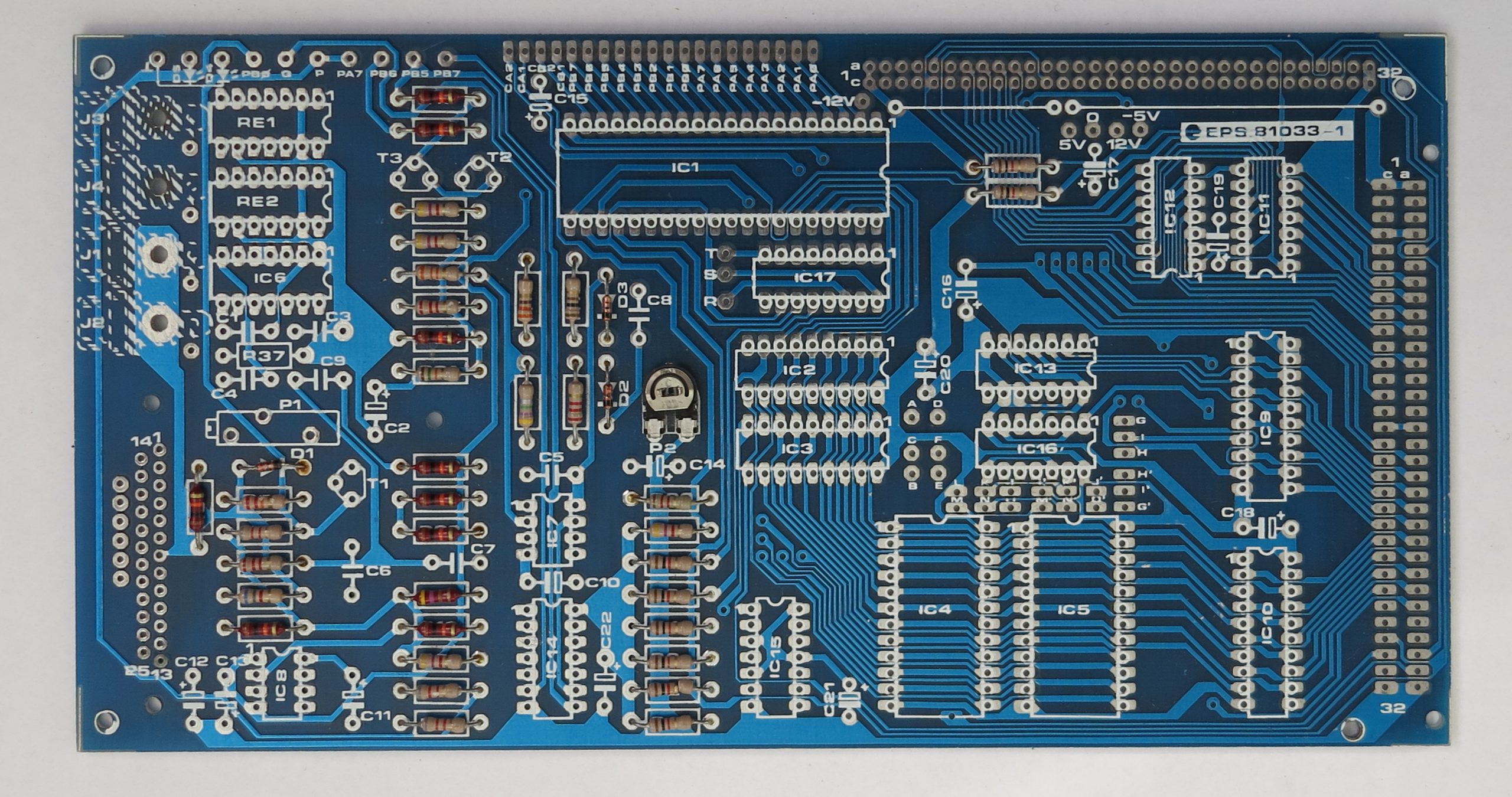
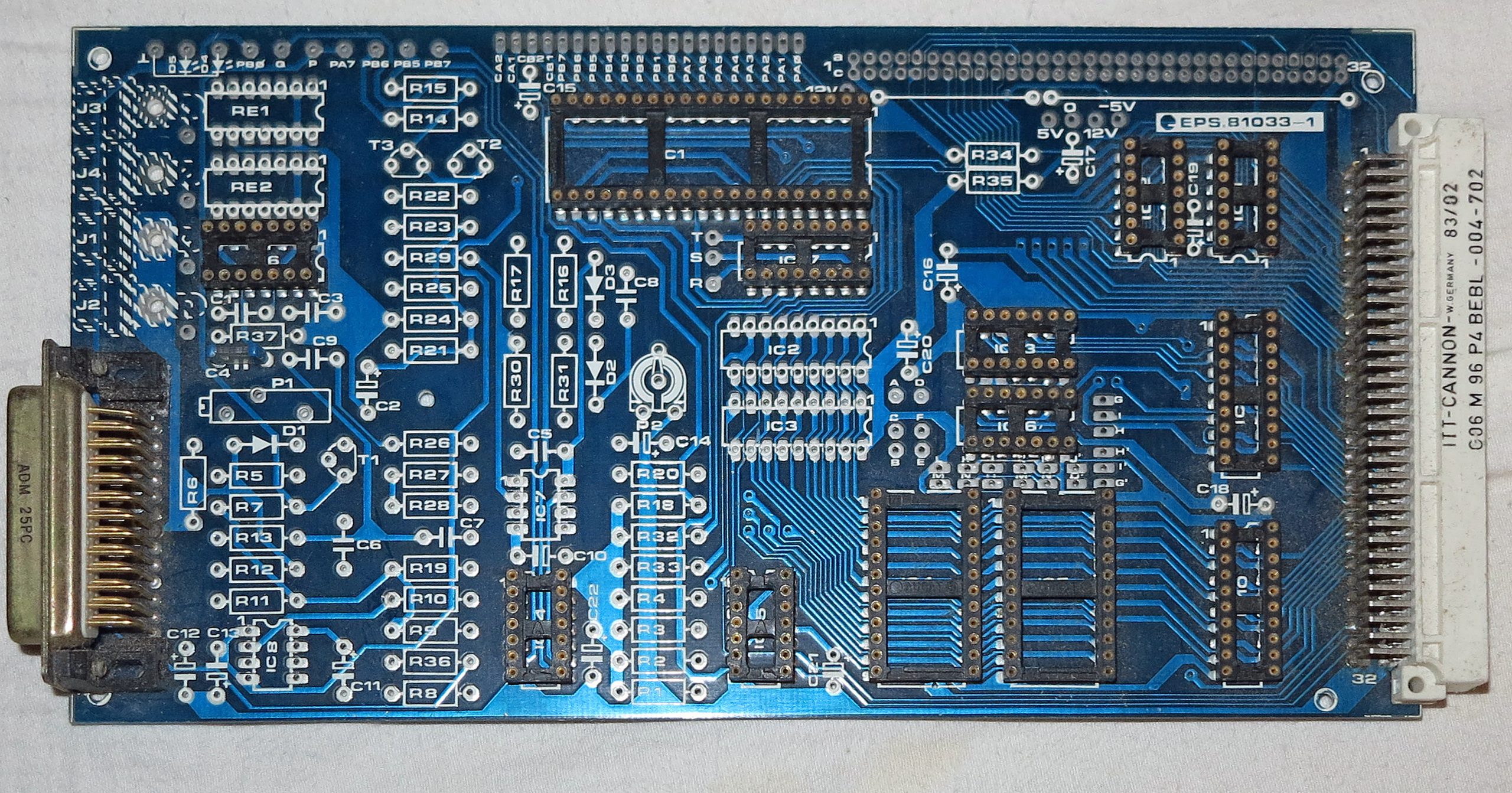
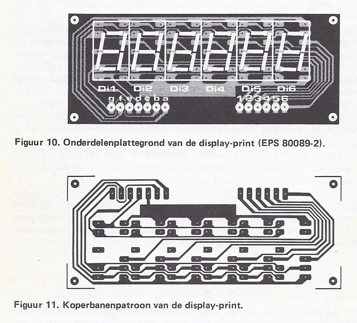
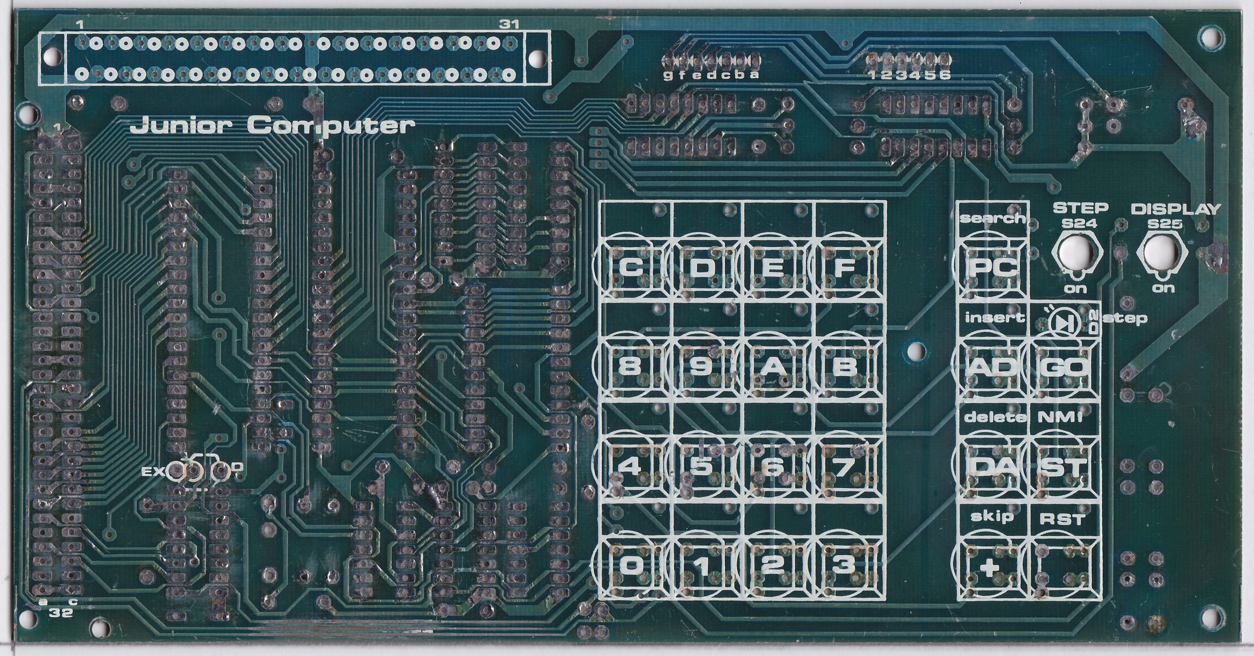
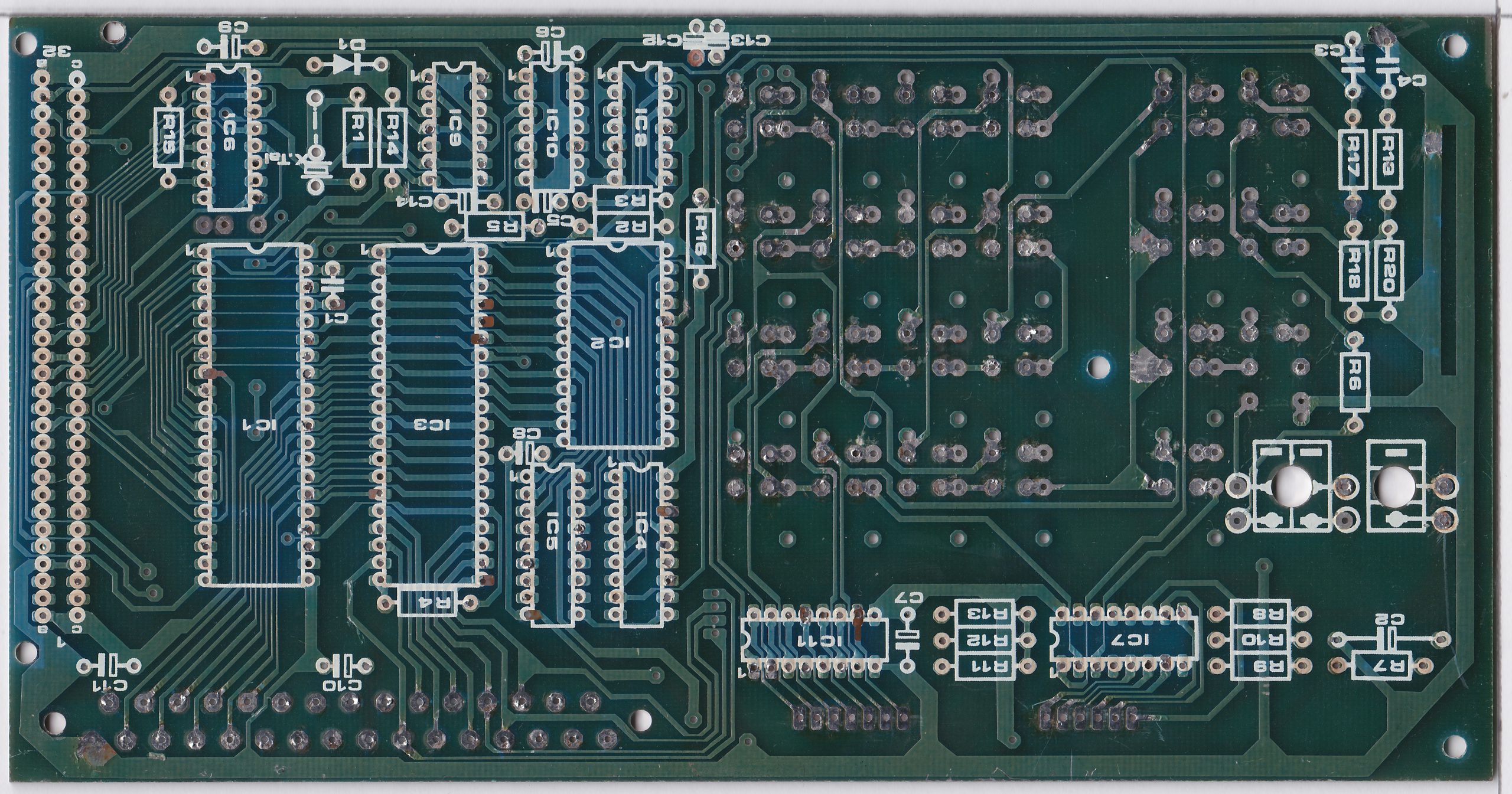
The Elektor designs sometimes use the 82S23 bipolar 32×8 PROM as memory decoder. The Junior Interface card is an example and a troublemaker nowadays: rare, expensive, hard to program.
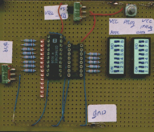
On this page some simple programmers are shown for this quite rare device.
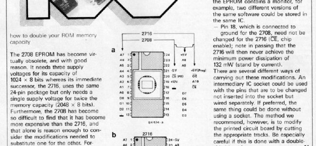
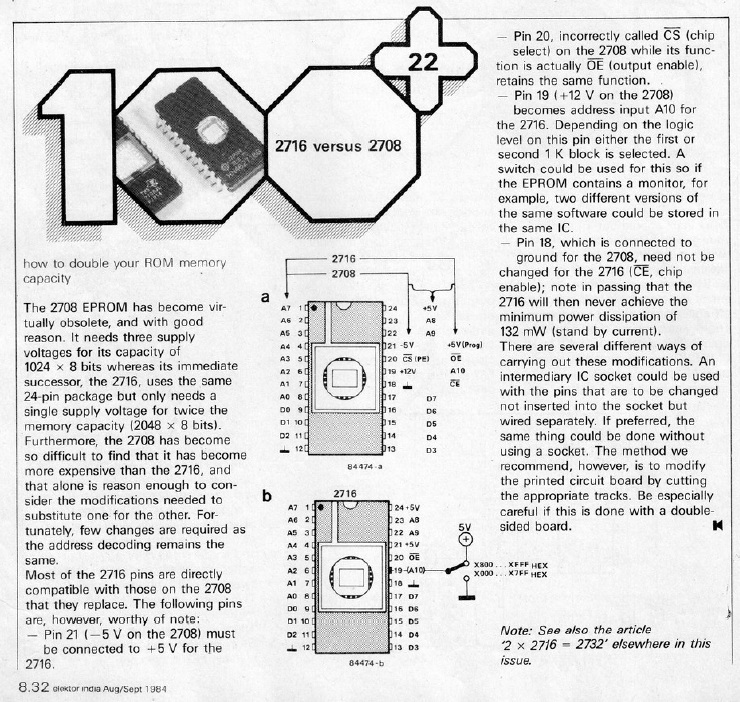
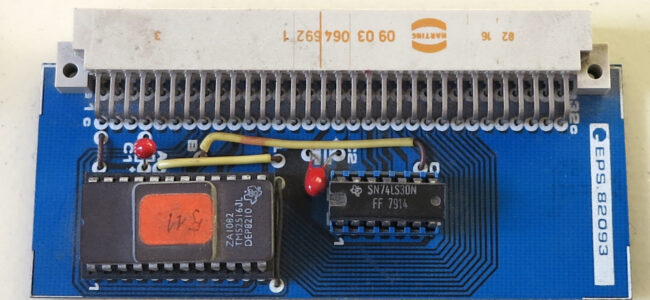
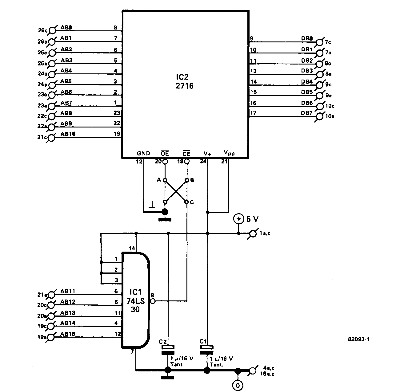
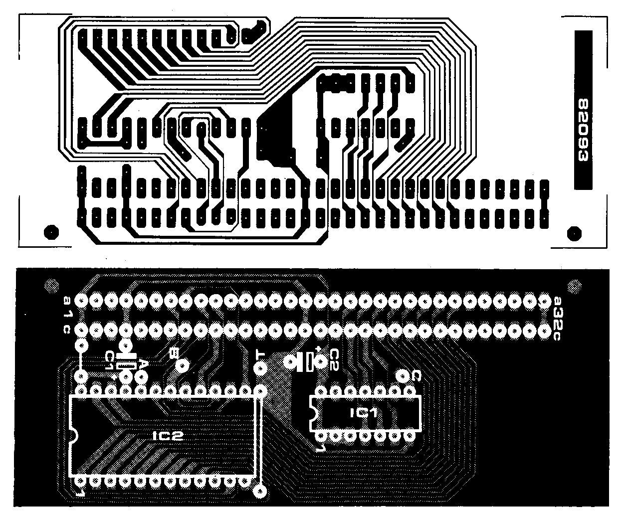
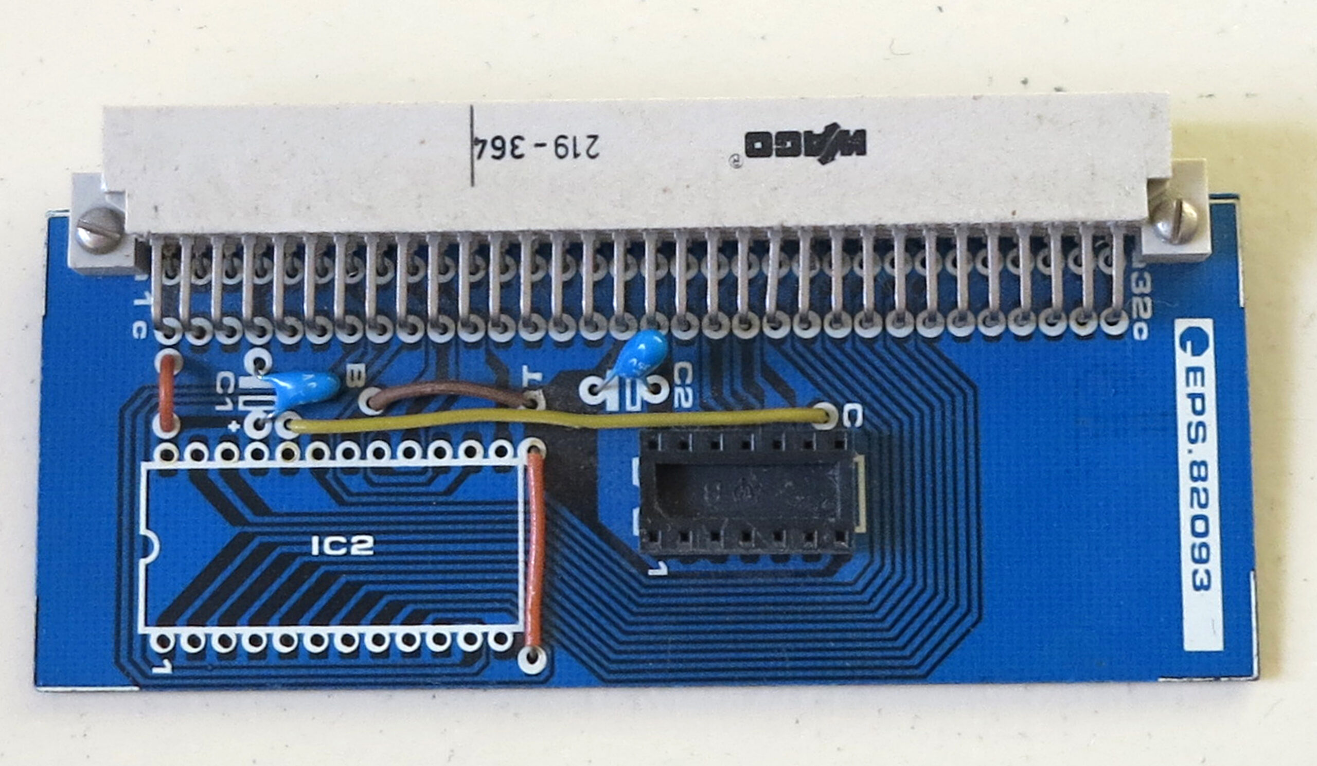
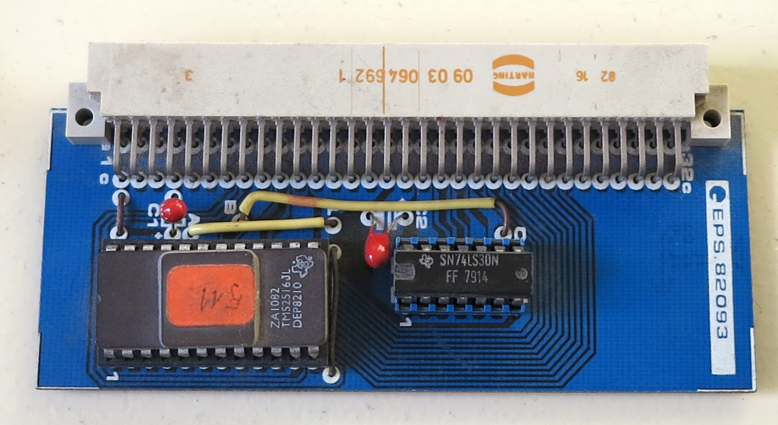
An alternative would be to use a 2716 or similar EPROM, 5 address lines as input, 8 datalines as output, via a converter PCB. FAst enough for the Junior at 1 MHz, but a bit bulky.
Or use a GAL instead. Small, easier to source and also reprogrammable.
On this page:
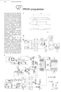
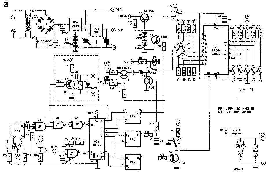
Elektor PROM programmer
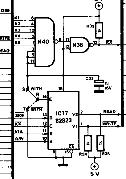
The circuit of the Elektor circuit (the article is listed below):
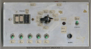
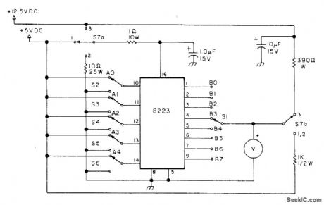
It can be much simpler (see the “An 82s23 programmer, Radio Electronics 1976” below):
All programmers require you to program one bit at a time. See the Signetics Programming Notes how to).
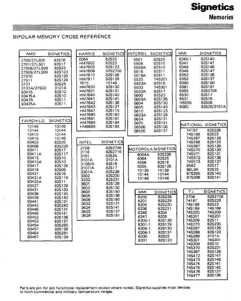
Bipolar memory cross reference
Alternatives for the 82S23 (or 82S123 with open collector outputs, add a pullup resistor to the outputs).
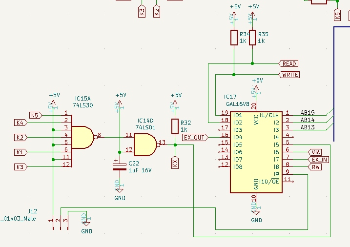
Use a GAL to replace an 82S23 or 82S123
In the DIY Build a Junior » Junior Computer Replica by laurent-fr design, a GAL is used to replace the 82S23. Have a look at his github page, here an extract. Note that this design is not tested yet (October 2022), so take care.
The original circuit:
Replace with:
GAL Design files by laurent_fr
Replace a 82S123 with a GAL
From the article REPROGRAMMABLE 82S123, local copy of the original article.
This project came about because I needed a way of experimenting with the data in an 82S123 PROM, changing it and seeing how the PCB reacted to the changes. As the 82s123 is a one time programmable device, this would work out very costly to make 20-30 changes in it’s code! The obvious way to do it would be to use an EPROM, but many of these are not as fast as a Bipolar PROM, so another solution was needed.
Enter the GAL! The GAL is a reprogrammable logic device that allows you to combine logic functions onto one chip, to save space on a PCB, or for custom logic equations. It can also be used for small amounts of data storage, but because of the way it is designed, it can’t hold a huge amount, but the 22v10 is certainly enough for the 32×8 bits of the 82S123.
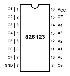
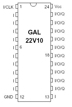
The pinouts of each IC are shown above. The GAL is flexible on what pin does what. Pins 2-11 and 13 are dedicated inputs. Pin 1 can be used as a clock for flip flops (not used in the application). Pins 14-23 can be either inputs or outputs, depending on how you want to configure them.
If we want to simulate an 82s123, we’ll need:
- A0-A4 inputs
- CE Tri state enable
- O1-O8 outputs
The easiest way to connect them on a breadboard is by the diagram below
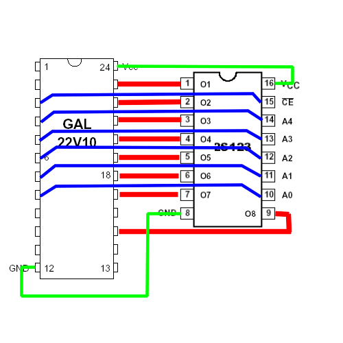
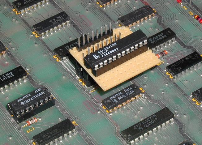
We use pin 3 on the GAL as the Tri state output control, pins 4-8 as the address inputs, and pins 15, then 17-23 as the outputs. I disable pin 16 in the code, as it makes life easier on the breadboard. Blow is the completed breadboard and programmed GAL, running as the DRAM control PROM on an Atari Missile Command PCB
It’s that simple! You can then remove the GAL from the breadboard, reprogram it in your burner, and use it again as many times as you like. It’s also a lot cheaper to buy than an 82s123 in the first place!
Here is the code in CUPL that I used for this device
Name 32x8prom;
Partno 32x8prom;
Date 06/06/03;
Revision 02;
Designer Mark Haysman;
Company Leopardcats;
Assembly None;
Location None;
Device g22v10;

/** Example of 82s123 simulation **/
/** Uses Missile Command DRam Prom PR0058 Data **/

/** Inputs **/


Pin 8 = d0;
Pin 7 = d1;
Pin 6 = d2;
Pin 5 = d3;
Pin 4 = d4;
Pin 3 = tristate;
Pin 16 = dummyinput;

/** Outputs **/

Pin [17..23] = [Q6..0];
Pin 15 = Q7;


/** Declarations and Intermediate Variable Definitions **/

field byte = [Q7..0];
field address = [d4..0];

byte.oe = !tristate;
dummyinput = 'b'0;
dummyinput.oe = 'b'0; /** Pin 16 is disabled **/

table address => byte {
0 => 0;
1 => 0;
2 => 0;
3 => 0;
4 => 0;
5 => 0;
6 => 0;
7 => 0;
8 => 0;
9 => 0;
a => 0;
b => 0;
c => 0;
d => 0;
e => 0;
f => 0;
10 => ee;
11 => dd;
12 => bb;
13 => 77;
14 => ee;
15 => dd;
16 => bb;
17 => 77;
18 => fe;
19 => fd;
1a => fb;
1b => f7;
1c => ef;
1d => df;
1e => bf;
1f => 7f;
}
Here is a link to the PLD and JED files for this particular PROM. All you need to do to make your own proms is enter the data into the table in the CUPL file.
Good luck! Any questions, I’m always on hand to help – mark@leopardcats.com