
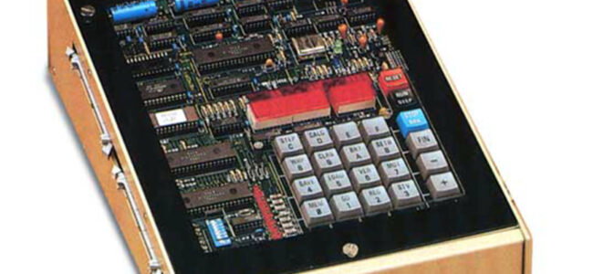
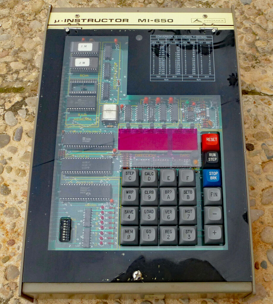
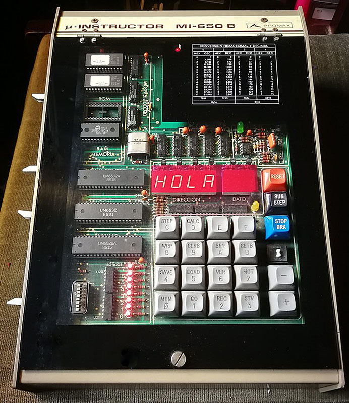
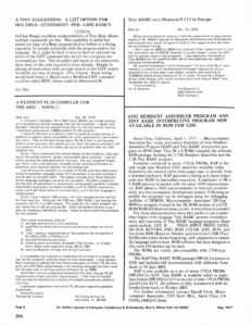
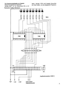
A Spanish firm developed a 6502 trainer, an SBC inspired by the KIM-1. Hexadecimal keyboard, 6 LED displays, I/O to experiment with. Assembled system, boxed, high quality components like mechanical keys. Aimed at education.
On this page:
- Introduction to Promax MI-650
- Manuals
- Monitor EPROM images and sources
- Images of MI-650
- Images of MI-650B
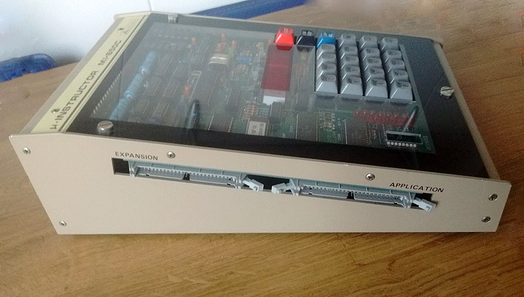
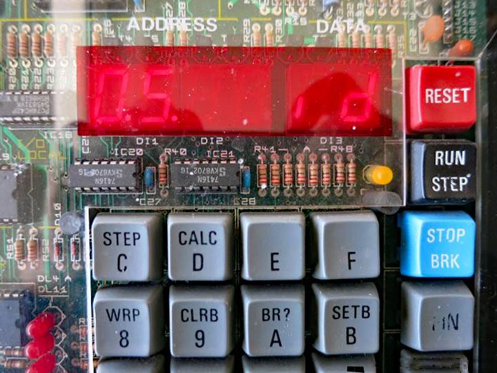
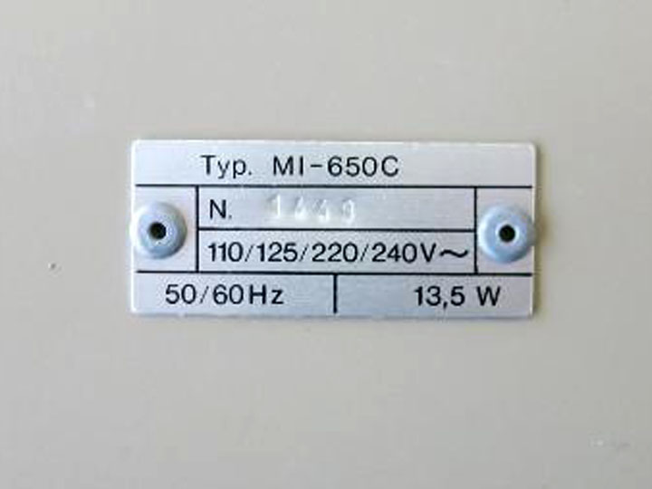
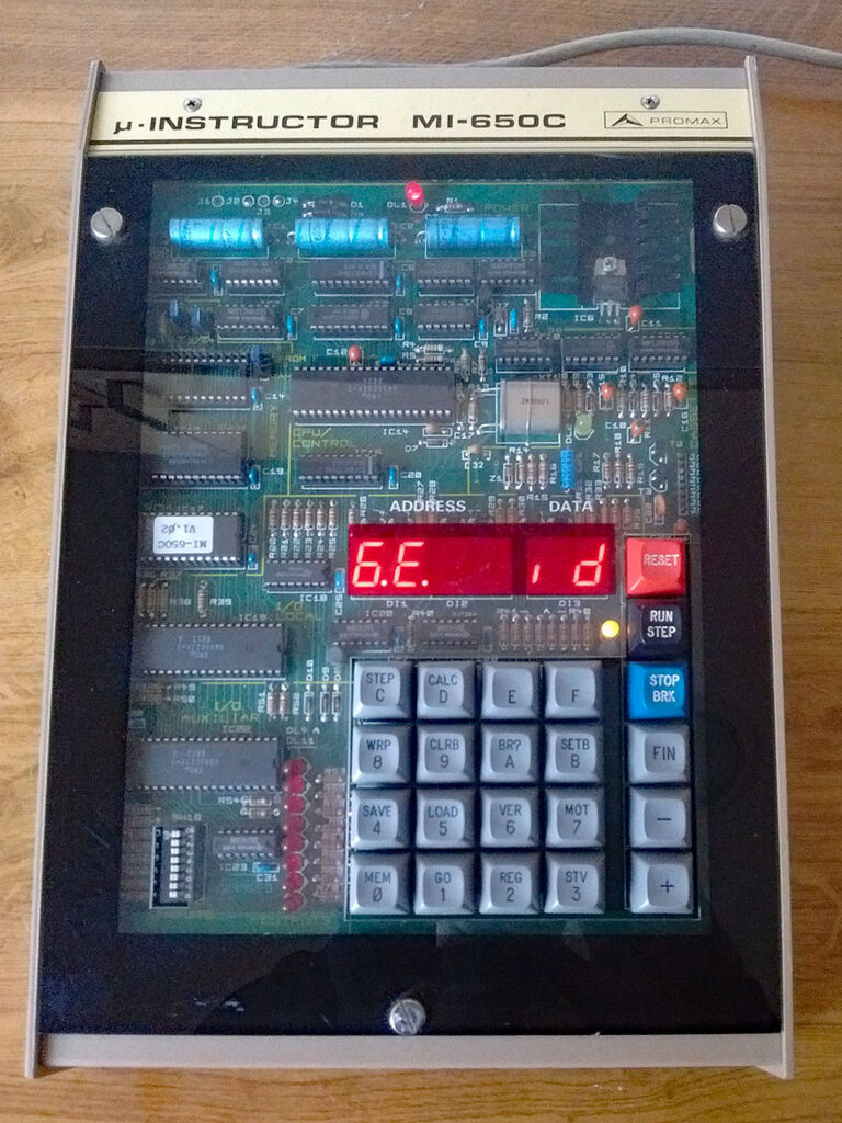
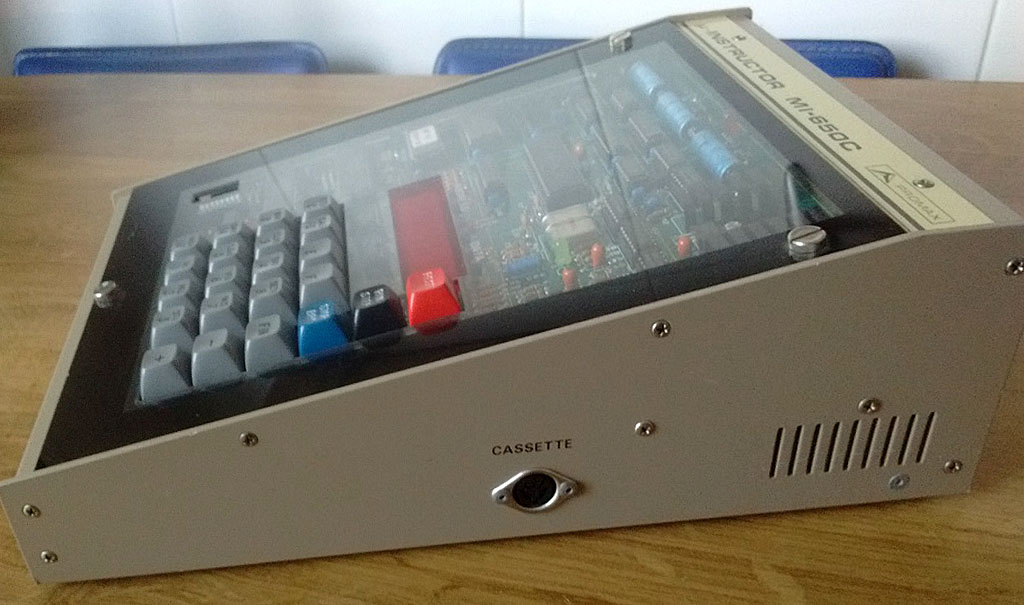
- Images of MI-650C
- MI-650 video demonstrations
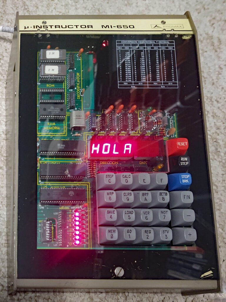
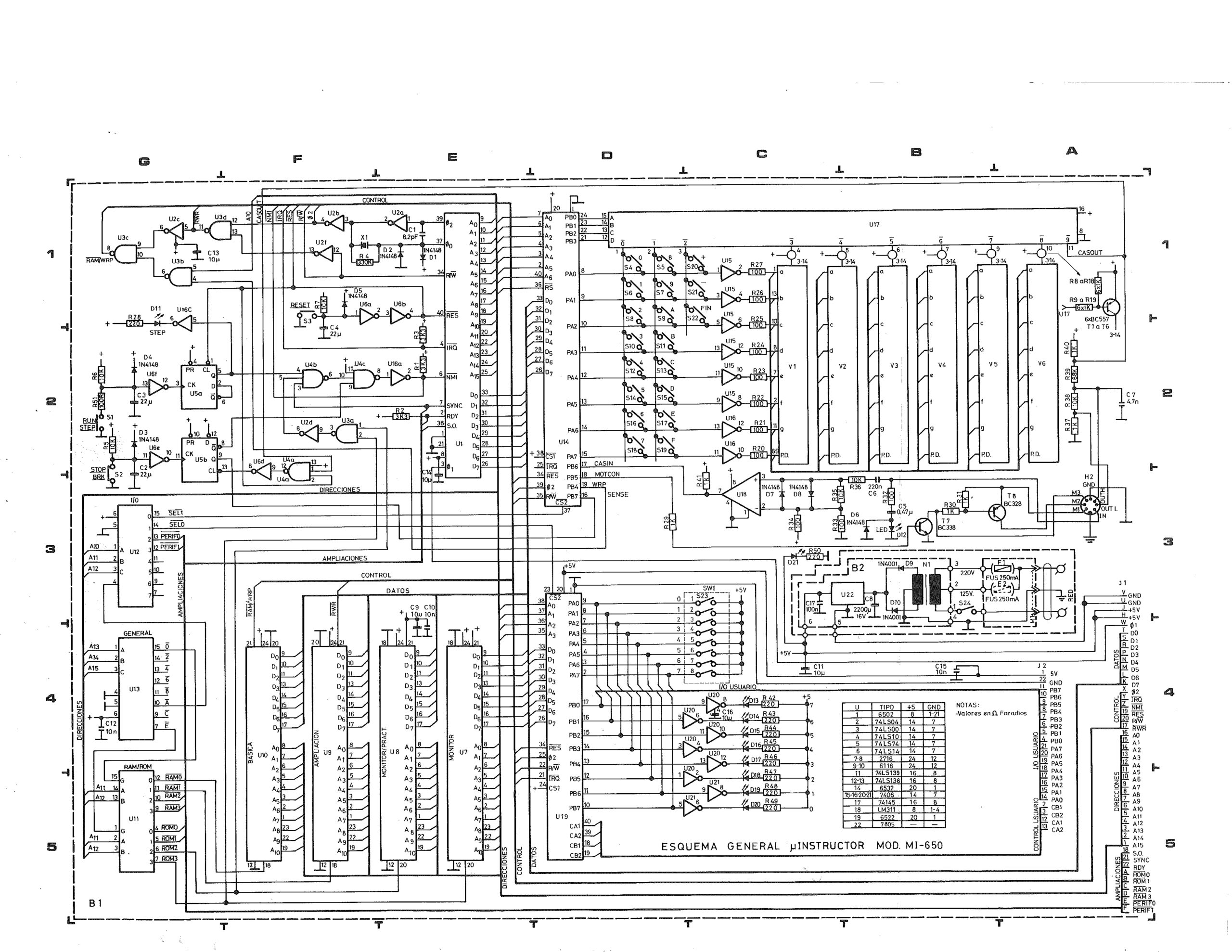
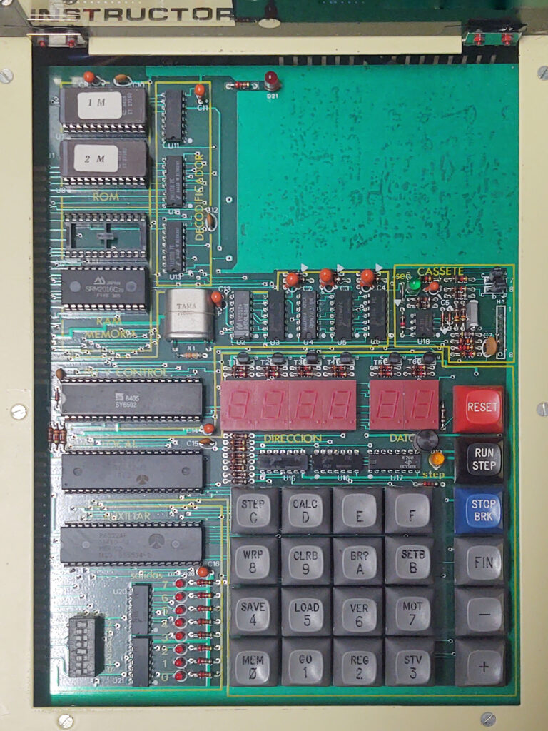
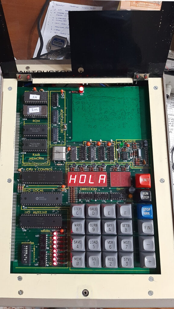
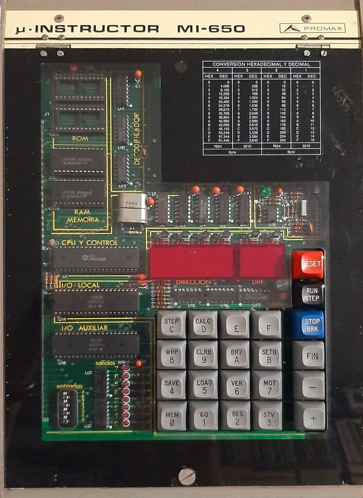
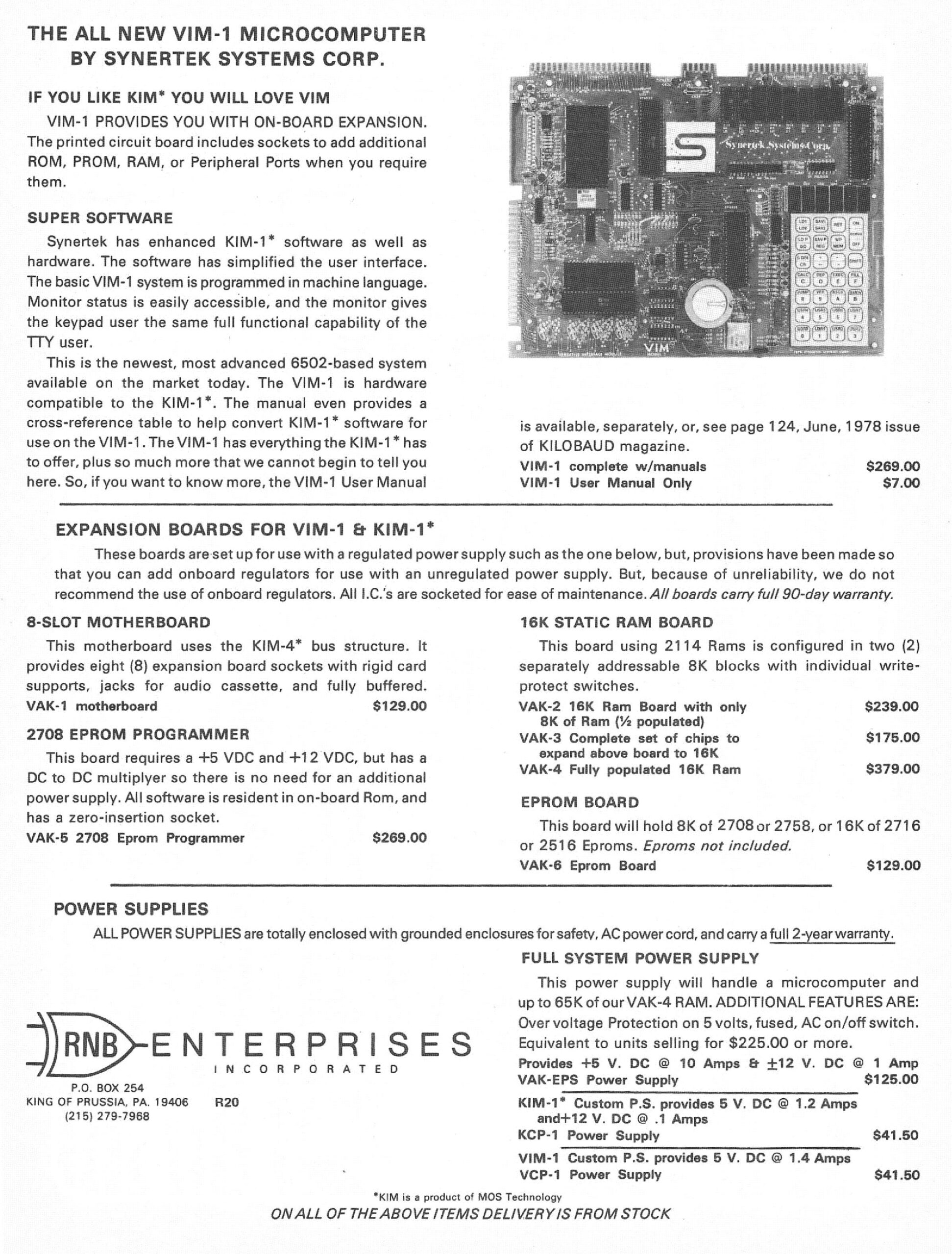
- MI-650. 6502, 6532 for keyboard/LEDs/audio cassette, 6522 for user I/O, 2×2716 EPROM, 2x2K SRAM. PCB fingers edge connectors for expansion.
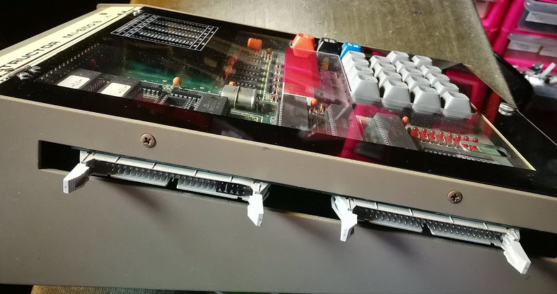
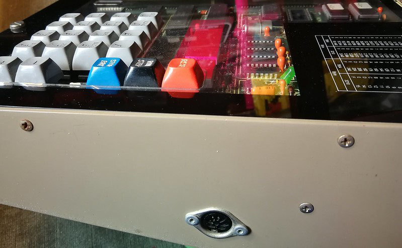
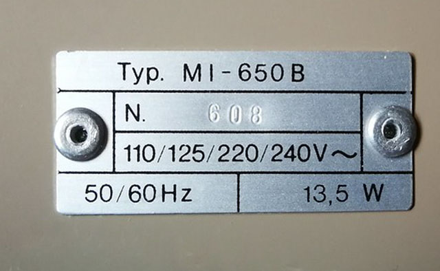
- MI-650B. equal to the MI-650, more convenient expansion connectors.
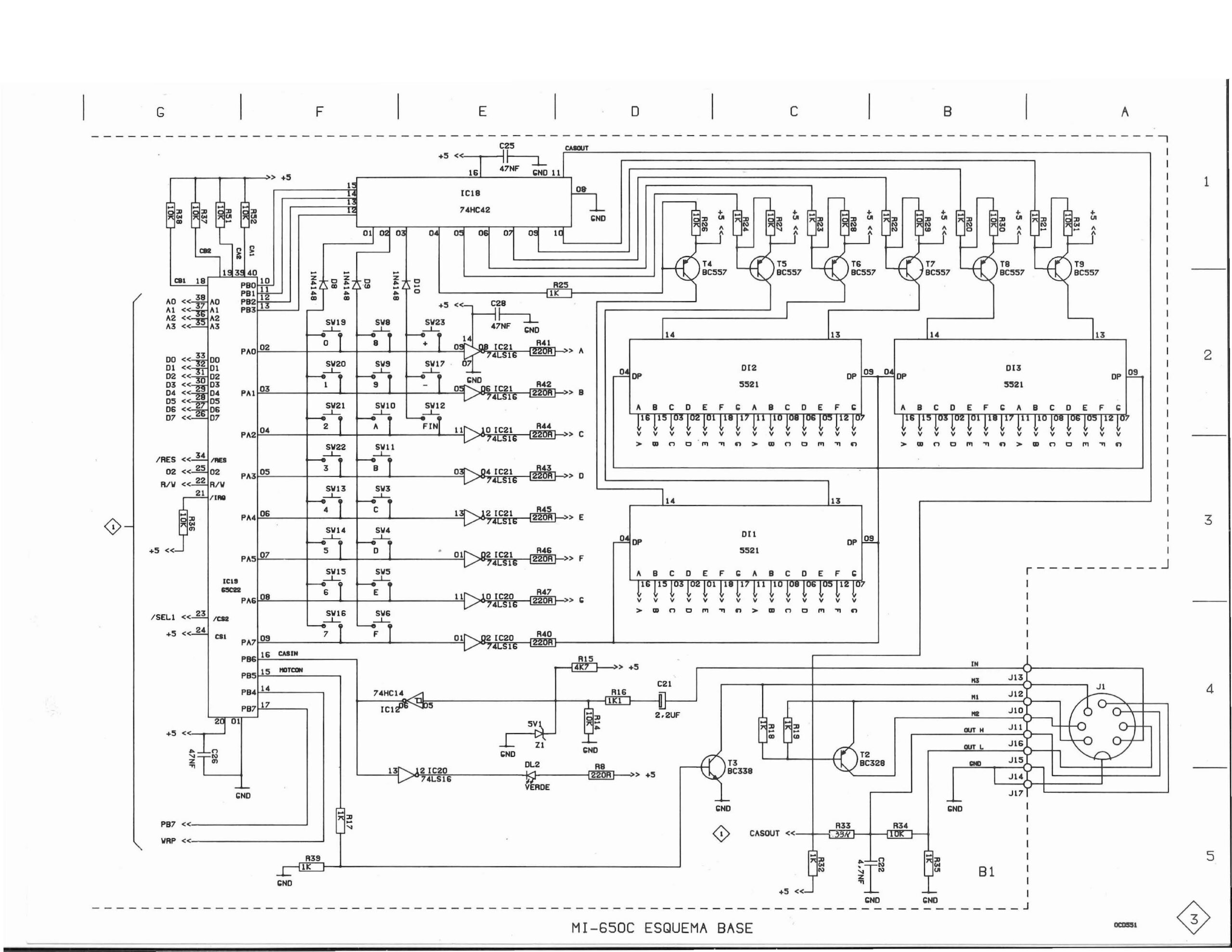
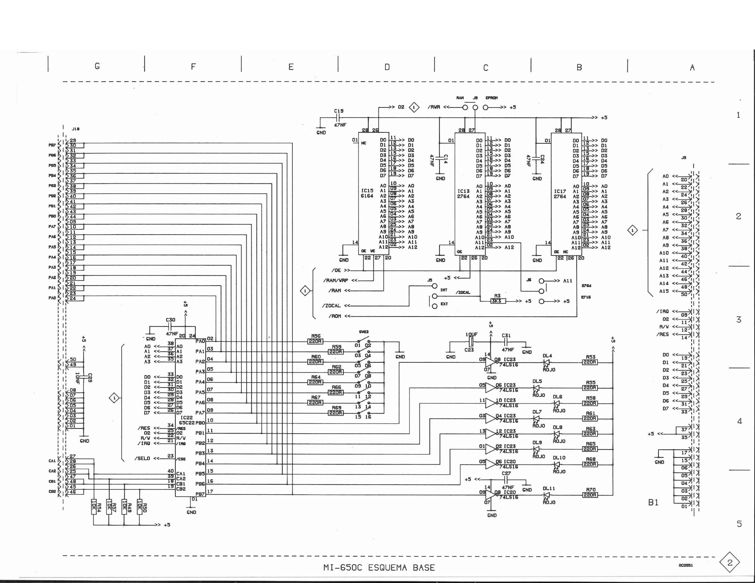
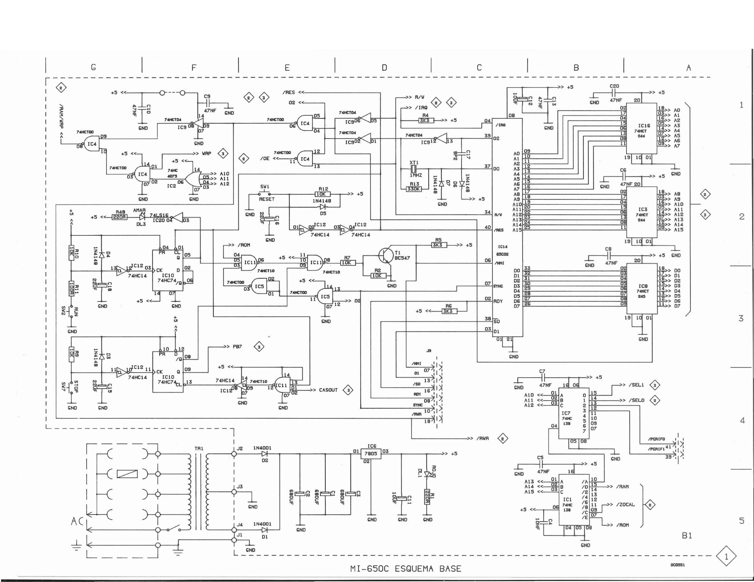
- MI-650C, a redesign, same dimensions and layout, with more modern components, like 65C02 CPU, larger EPROM and 65C22 for keyboard and LED.
All three share the same monitor program, patched for the MI-650C to use the 6522.
![]()
Statement by Promax about the 1979 Educational trainers
Educational instruments division was the result of our close commercial relationships with universities and technical schools. Work here was closely tied to the study plans of universities and technical schools in order to provide the educational material required by a variety of disciplines. Design work was begun on the MI-650B Microprocessor Trainer, based on the 6502 which appeared in 1975.
Updates from various sources, motivated by the find of Jose Vicente Marques Vidal of four MI-650s and our attempt to make them operational again (missing EPROMS mostly).
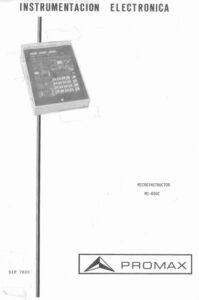
Manuals
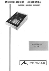 |
PROMAX MI 650 μ-instructor |
|
PROMAX MI-650-C Microinstructor (contains ROM listing and more) |
 |
Microprocesadores de 8 bits 6502 promax MI-650C microinstructor |
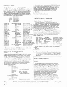
Monitor EPROM images and source
EPROM images are supplied by John Evans (in the KIM-1 Facebook group) and Youtube user @eeep73 and Dominic Bumbaca.
Identical dumps from two different MI-650s, so good dumps!
Archive with Promax MI-650 EPROM images (2x 2716 EPROMs).
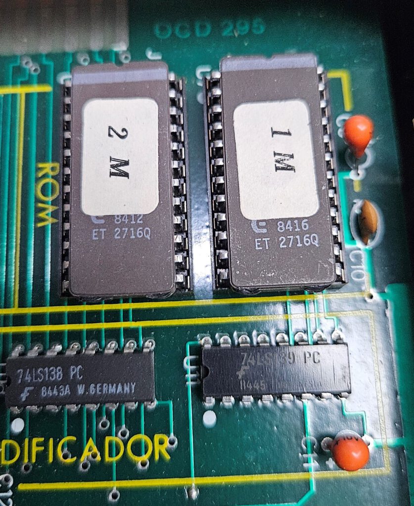
Photo by Dominic Bumbaca
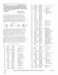
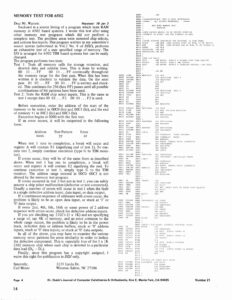
The MI650C manual has a listing of the monitor. This has been used to reconstruct the source of the MI-650 and the MI-650C monitor.
The resulting binary of the MI-650 monitor is checked against the ROM dumps and they are identical.
The source of the MI-650C is for most of the code identical to the MI-650 source. What is different is the IC used for the keyboard, LED displays, audio cassette control. The MI-650C has replaced the 6532 for a 65C22.
The source code is converted to more standard MOS Technology syntax, the original Spanish comments are retained.
Archive with Promax MI-650 monitor source
Archive with Promax MI-650C monitor source
MI-650
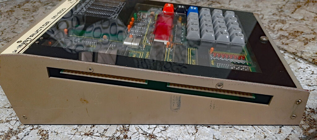
MI-650B
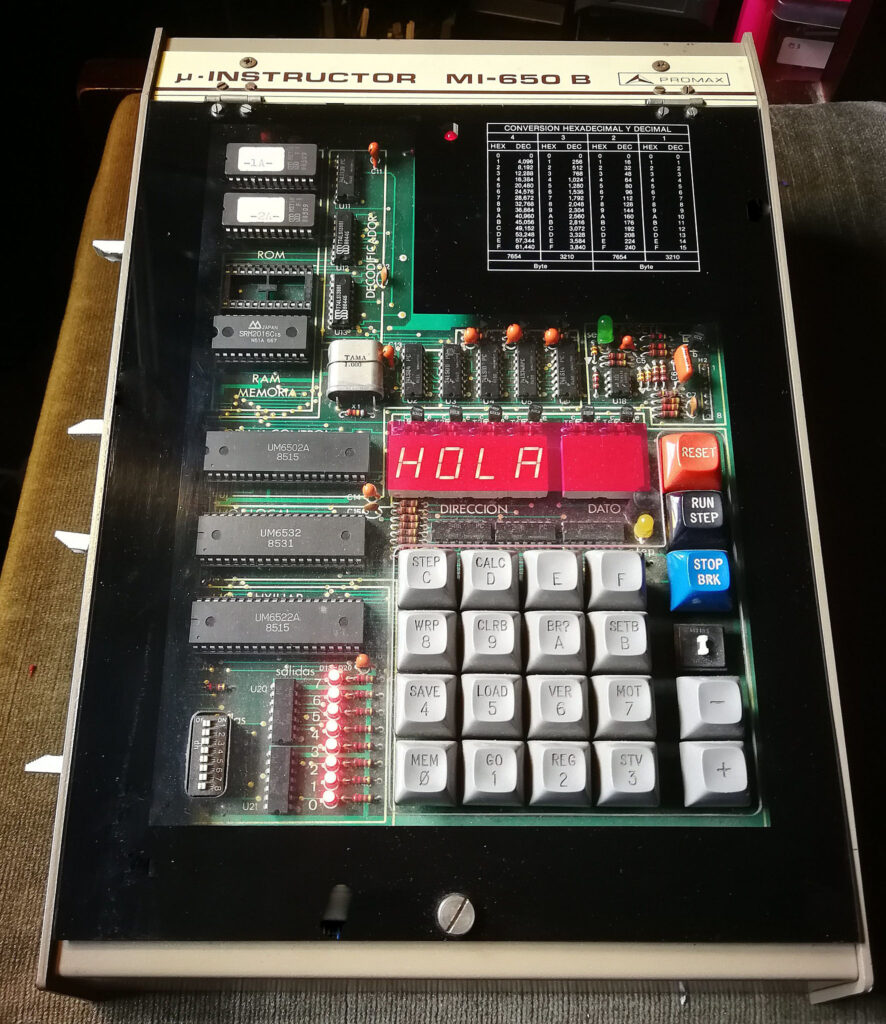
MI-650C


Videos
Videos of MI-650 demonstrations
https://www.youtube.com/watch?v=PypHSDdsIX


