R65 – A late seventies computer built with a KIM-1 by Rene Richarz.
All information on the R65 and the emulator of this computer on the github archive of Rene Richarz, a work in progress!
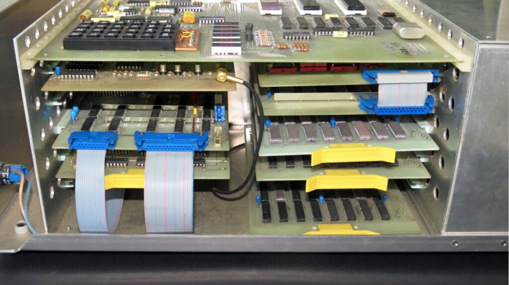
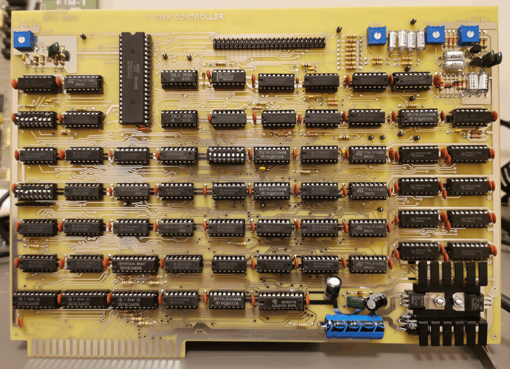
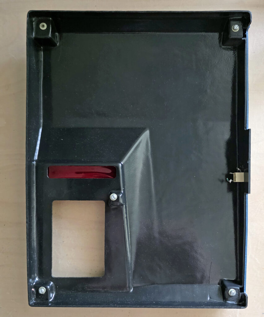
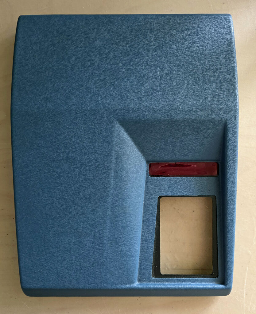
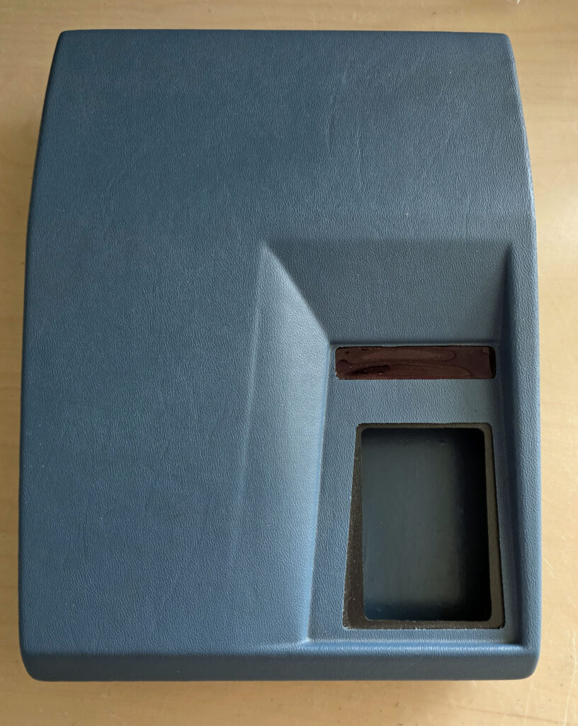
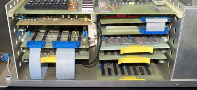
Original Job computer built 1977-1979
The R65 computer has been built 1977-1979 by Rene Richarztogether with Rudolf Baumann, who has built his own JOB computer at the same time with similar hardware. The picture above shows the open JOB computer. The original R65 computer has not survived. The floppy disks have also not survived.
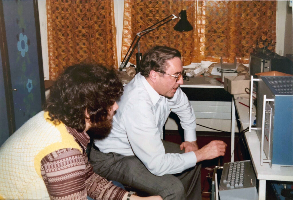
Rene Richarz (left) and a guest looking at the R65 system
Hardware specifications of the original R65 Computer:
– 6502 8-bit microprocessor
– 1 MHz clock speed
– 17 kByte, 33 kByte, 49 kByte RAM (expanded 2 times between 1977 an 1979)
– 2 kByte graphics RAM
– 10 kByte ROM
– 40 x 16 char monochrome display
– 224 x 118 dot monochrome graphics display (switchable with char display)
– 2 floppy disk drives. Formatted capacity 199680 bytes each.
– Interfaces: Teletype, RS232, parallel printer, audio tape, golf-ball typewriter, tv
Most of the original 6502 assembler programs have been written by Rene Richarz 1977 – 1980, some of them based on code snippets found in publications. They have been modified and improved up to 1982 by Rudolf Baumann for his hardware. Thanks to him for keeping his hardware (not functional anymore) and printed program listings up to today. The program listings have been scanned and digitized 2018 by Rene Richarz.
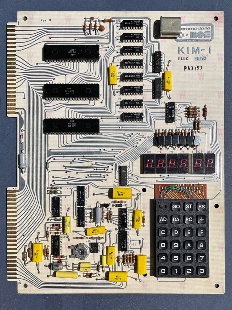
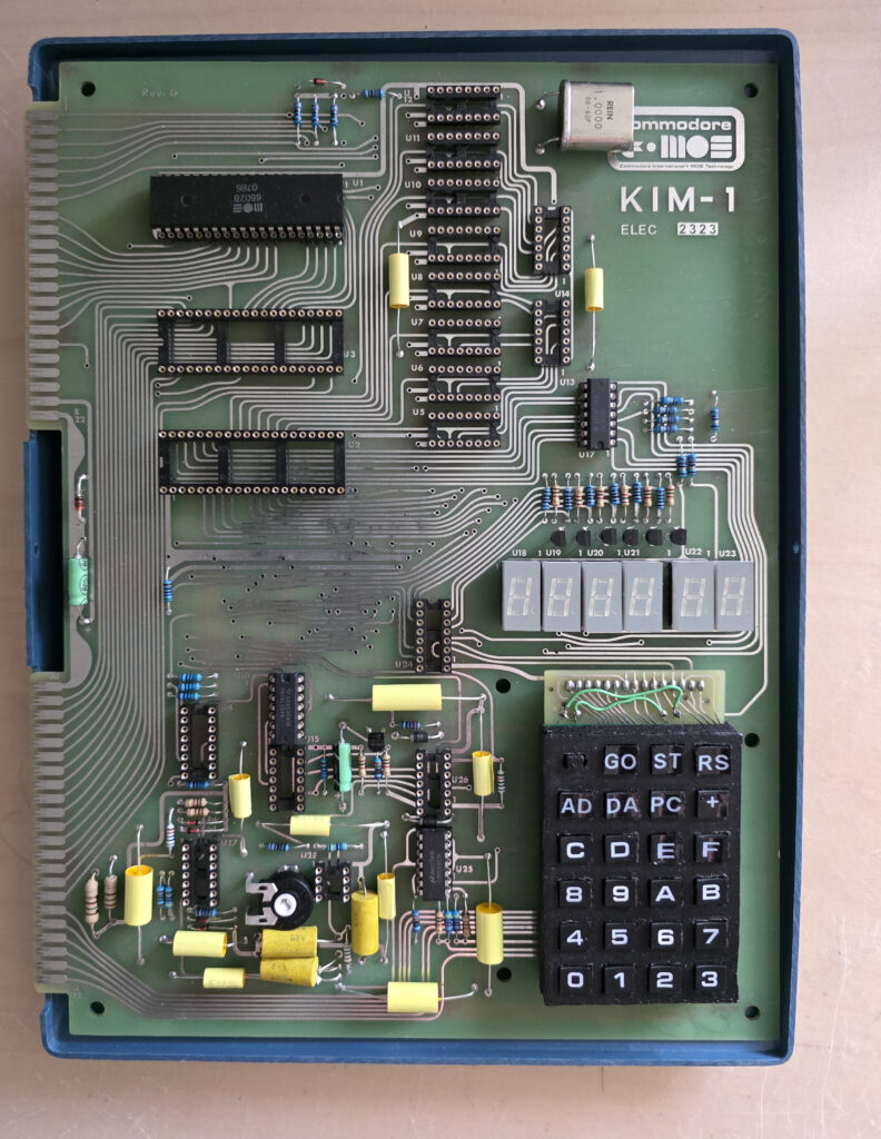
The main software includes the original KIM-1 ROM and 4 modules, which were burned on EPROMS at that time. These modules are:
– A system monitor module, which is executed at startup
– A disk controller module, which handles the access to the floppy drives
– A IO controller module, which handles other IO
– A CRT controller module, which handles the display
These 4 modules run in their original version, with the exception of a few minor bug fixes.
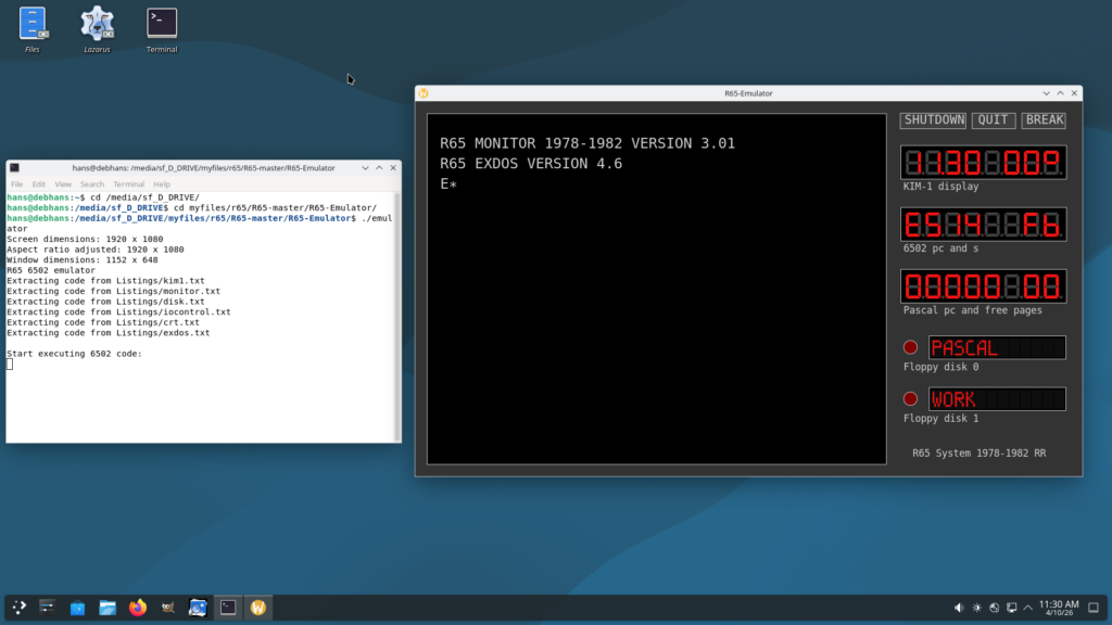
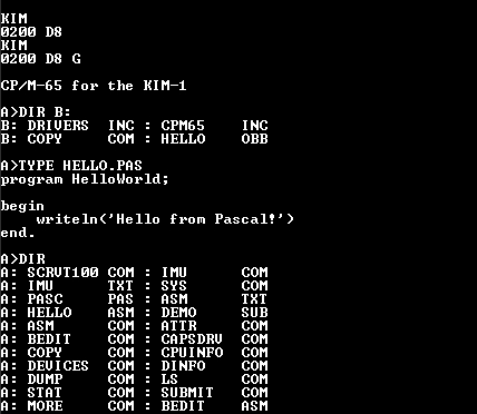
Emulator
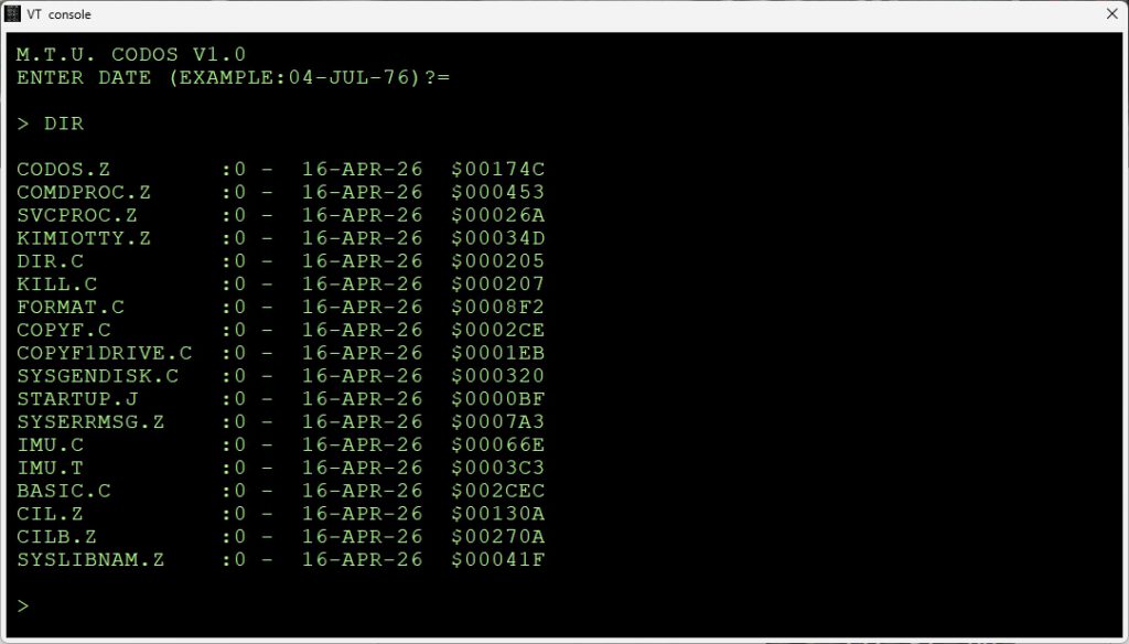
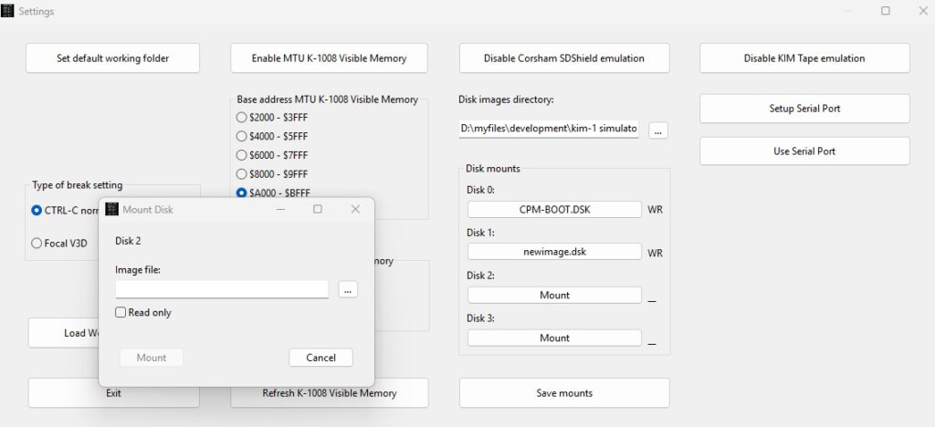
The software also includes an extended disk operating system module (EXDOS), which has been modified substantially. A number of commands have been added to the emulator version of the extended disk operating system module. They allow to import and export serial data files to and from the Linux operating system and to “change floppy disks”. The emulator emulates 2 floppy drives as in the original system, but can handle an unlimited number of floppy disks.
The original text editor has not been implemented, because it must be considered very user unfriendly given todays standards. Instead, using the “edit” command of EXDOS, the file to edit is automatically exported to the Linux file system, and the Linux text editor “mousepad” is called. Once mousepad is quit, the edited file is imported automatically back into the R65 file system. This happens automatically and very quickly.
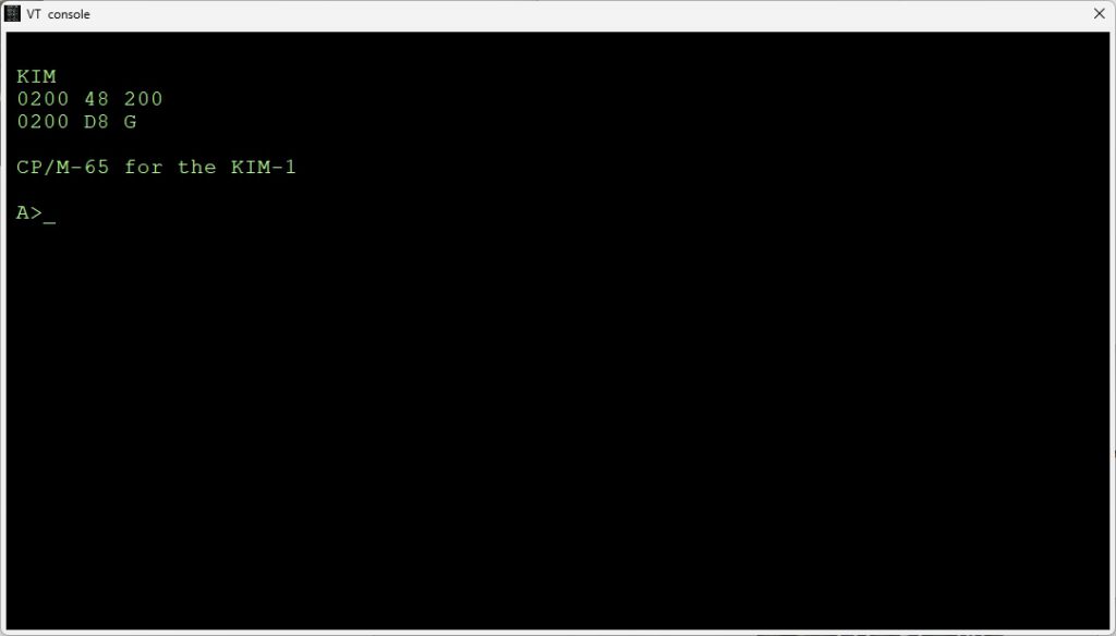
Please note that even so the emulator includes the original KIM-1 ROM, it is NOT a KIM-1 emulator. Only the KIM-1 hardware required for the operation of the R65 computer system is emulated in the emulator.
The emulator uses a very nice 6502 emulation module written 2011 by Mike Chambers (miker00lz@gmail.com). The look and feel of the emulated system is very similar to the original. But everything is much faster.
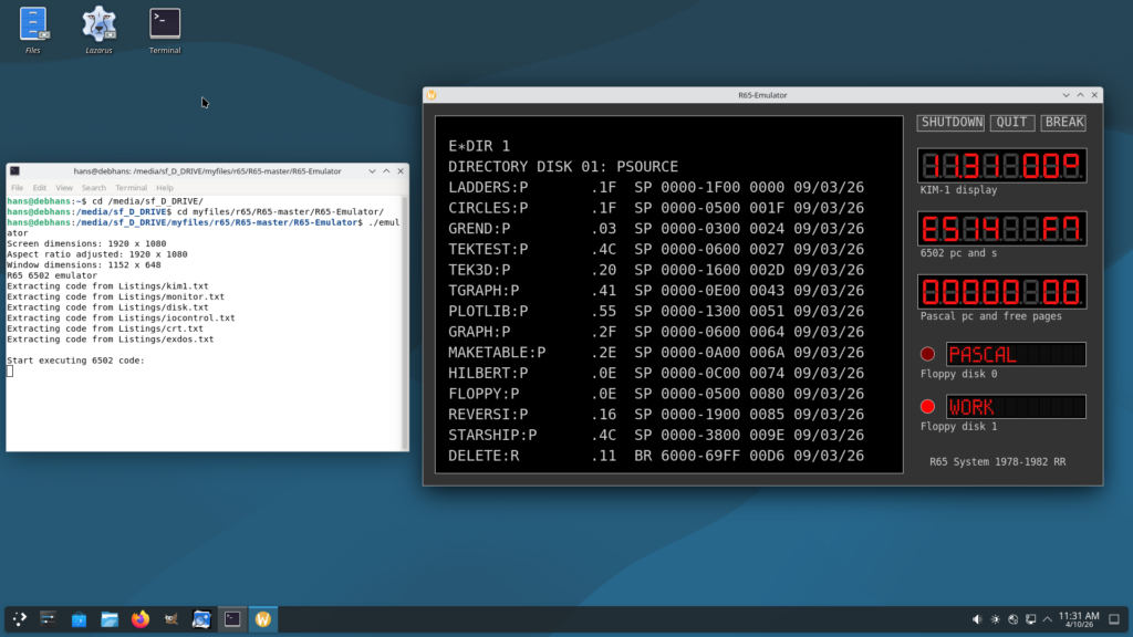
The original R65 computer included a BASIC interpreter, and an improved Tiny Pascal compiler. The R65 Pascal system, which was quite powerful for a 8-bit microprocessor at that time, and the BASIC interpreter have been reconstructed.
The floating point subroutines of the R65 Pascal system were published in Dr. Dobbs Journal, Volume 1, Number 7, August 1976, page 17 by Steve Wozniak.
It is easy to compile and run the emulator on any Debian system. The installation is well described.
You may have some trouble with the font installation, the script failed for me on bot the Raspberry as Debian Linux X86 due to protection errors. I copied the fints by hand and set the file protection to read for the world.