Junior Computer ][
Written by 2021 by Joerg Walke, visit his website for the most actual version!
The Junior Computer ][ is an expanded version of the original Junior Computer. To make it more useful, I’ve equipped it with 32KB RAM, 8KB ROM and an onboard RS232 serial interface for connecting a terminal or a printer. For the use with a terminal, I also wrote an extended monitor program thats included in the bigger ROM. The development of the Junior Computer ][ is still in progress, so some other features will find its way to the mainboard.
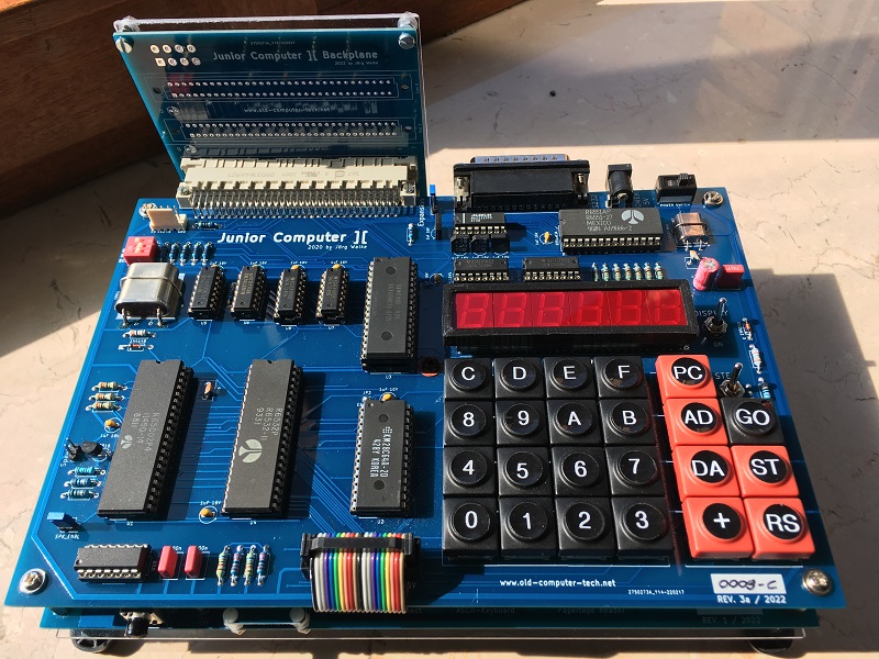
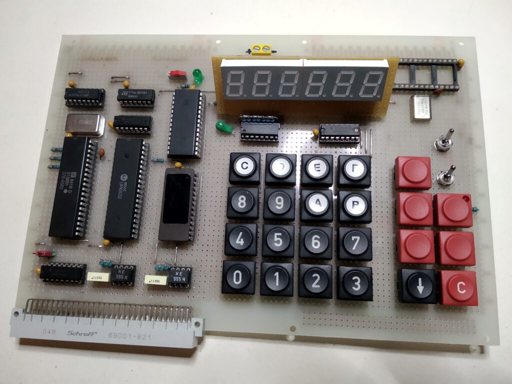
On the picture above, you can see the actual rev. 2 board of the Junior Computer ][.
The new revision 3 board has arrived!
…all components assembled and soldered
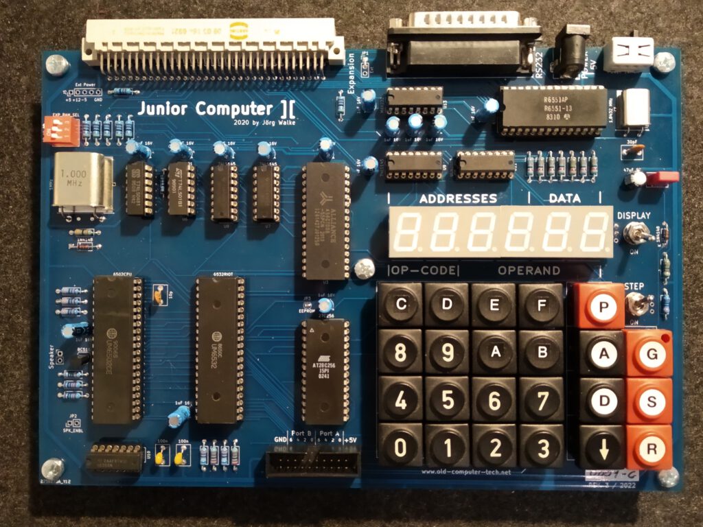
…and it works fine!
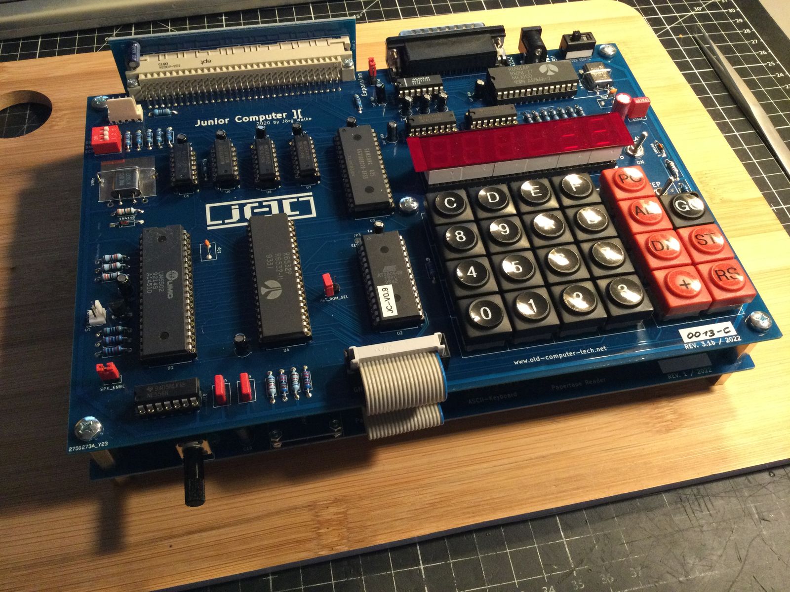
Its new features are: Up to 128KB RAM chips installable. 3 DIP switches to configure three additional 8KB RAM banks. Maximum of 51712 Bytes usable with 64KB RAM chip. Auto reset at power on. A power switch (oh yeah). Usable Memory for string buffers in the address area of the ACIA.
Edit August 2022: there is now also a I/O card and a bus card!

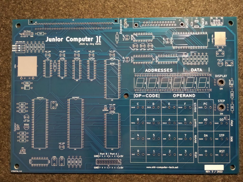
The Computer is divided into two parts. On the left side are the main computer components. The 6502 CPU, 6532 RIOT (RAM, Input/Output and Timer), ROM (8 KB EPROM), RAM (32 KB SRAM), the 1MHz quarz cristal and some 74LSxx logic chips for address decoding and clock generation. There is also a double timer chip on the lower left corner for debouncing the Reset (R) and Stop (S) keys. On the top lies the (in the picture not populated) expansions connector. And on the bottom side there is a connector for the two 8 Bit I/O ports coming from the 6532 RIOT. A small transistor amplifier on port B0 can be used to drive a loudspeaker, to make some simple noise.
The input/output components of the Junior are on the right side of the PCB. There is the hexadecimal keyboard, for entering the program addresses and data. And there are also some control keys. Above the keyboard is the six-digit, 7-segment display for showing the addresses and the data bytes as hexadecimal coded numbers. The display can also be switched off, if not needed. Keyboard and display is controlled by the two 8-bit I/O ports of the RIOT, by alternately polling the keyboard and repeatedly writing each single digit of the data to be shown on the display. On the top of the I/O side is the 6551 ACIA (Asynchronous Communications Interface Adapter) chip and a level shifter for the RS232 serial interface signals. The little quarts aside the ACIA is for the baud rate generation, which ranges from 50 to 19200 Baud.
I built the first prototype in July 2020 on a breadboard, followed by the rev. 1 PCB in August 2021.
The rev. 2 board was necessary, because unfortunately the distances between the input keys were a little bit too narrow. Also the rev. 2 board had some issues. But it worked fine for me. After publishing the JC][ on the Classic Computing forum (www.classic-computing.de), I found some people who were interested in it. That charged me to make some further expansions and to make it a little bit more useful for others. The revision 3 board with some improvements is now on the way, as is new software.
The schematics and Gerber files for the PCB and of course the ROM images and the 6502 Assembler source code files are freely available on the download section. So feel free, to make your own Junior ][ and have some fun with 8 bits.
Programming the Junior Computer ][
Programming the Junior is quite simple:
Apply power and press the (R)eset switch. The display turns on and shows a random memory address (four digits) and its content (two digits). The Junior Computer ][ and its predecessor are both programmed in raw 6502 machine language. That is, each CPU command is entered in its numeric representation as a hexadecimal number. For example, 4c 00 F8 means: Jump (4C) to absolute location F800. 16-bit values such as memory addresses are written as the lowest byte first, so the byte representation 34 12 in memory represents the 16-bit value 1234 in hexadecimal.
To enter some data, you first have to type the address, were the data should be located. To do so, press the (AD)dress key and type in the four hexadecimal digits (16 bits) of the memory address location. Then press the (DA)ta key and type the two hexadecimal digits (8 bits) of the data. If you make a mistake, simply type in the new value. To enter data in the immediately following address, press the + Key (in my picture above, this is the down arrow key – because I just hadn’t a + keycap) and enter the new data.
To examine any address, you just have to press the (AD)dress key again and type in the address you want to visit. By pressing the + key, the direct successor address is displayed. Pressing the GO key executes the program at the currently displayed memory address. There is also a Edit mode where you can insert and delete data, and automatically calculate branch and jump addresses. To use this mode, please refer to the Junior Computer Book 2.
Another way to enter programs is, to use the extended (terminal) print monitor program. First you have to connect a VT100 compatible terminal to the RS232 interface and set it to
9600 Baud, 8 data bits, no parity, 1 stop bit
To start the monitor program, press the (AD)dress key, type in the address F800 and press GO. On the terminal display, you should now see something like this:
                                  Junior Computer ][

Print Monitor
2021 by Joerg Walke

(M)onitor  (L)oad  (S)ave  (A)ssembler  (B)asic ?
For now Monitor is the only selectable choice (but the rest will come soon, hopefully), so type M on the terminal keyboard to enter the Hex Monitor. The Display is cleared and a * prompt is shown. All input is non case sensitive, so typeing M or m is the same.
To examine the content of a single address, just type in the address as a hexadecimal number and press the Return key. The address and its current content is then shown.
*F800

F800- 4C
To view a hole block of data, enter the start-address and the end-address of the block to be shown, divided by a . (dot).
*F800.F808

F800- 4C DC F8 A4 F8 B1 F6 E6
F808- F8
To enter new data, type in the address where the data should be written, followed by a : (colon), followed by the single data bytes.
*200: 4C 00 F8

0200- 03
Execute a program by typing the start address followed by a G
*0200G

0200- 4C
To exit the Monitor and to go back to the main screen of the monitor type
*X
and then press the Return key.
If you want to go back to the standard Junior Monitor just enter
*1C1DG
(followed by Return) which leaves the terminal screen as a Zombie without a function and enables the 7-segment display and the hex keyboard.
That’s it. If you are interested in learning more about programming the 6502 and the Junior Computer, please refer to the MOS 6502 Datasheet and the Junior Computer books.
Downloads Junior Computer ][