While building the Retro Chip Tester, designed by Stephan Slabihoud, and documented on his 8bit-museum website, I noticed Stephan also designed CPU NOP testers and made designs as gerbers and BOM available. With the PCB of the Retro Chip tester I laso bought the PCB’s for 6502 and Z80 NOP tester from him. NOP testers are very simple test devices and in no way a real CPU stress test. Enough to discover if the IC is not a fake or severely damaged and not fit to be tested in a real system.
The idea of NOP testers is not new, for example Lee Davison documented his NOP tester for the 6502 here.
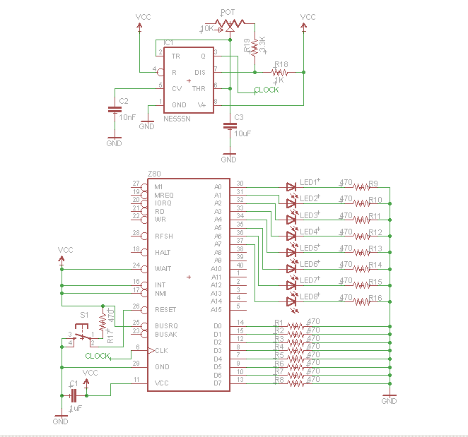
Stephan made the NOP testers standalone devices. Besides the socket for the CPU to test a clock signal is generated with a 555, a push-button does the reset, the minimal of control lines is connected to ground or puleld high, power is supplied with a USB connector.
The clock oscillator has a very low frequency, so you can see the address lines change by observing LEDs connected. This means the NMOS 6502 and Z80 are operated way below their minimal frequency, e.g. 100KHz for a 6502. The CMOS versions are static and can be driven with this low frequency.
In my experience with these testers is that the NMOS versions of 6502 and Z80 do work with this tester though, but I have seen good 6502’s start off well but after a minute crashed with all LEDs flashing in the tester. So not a definite test for NMOS! An interesting modification would be to have a higher clock frequency (1MHZ at least) and inspect all the address lines with an oscillosope.
Read the original articles and download Gerbers and BOM’s from the 8bit-museum.
6502 NOP Generator
Used in a 6502 NOP generator , a 6502 CPU only executes NOP commands (No Operation). The low eight address lines can be observed with the aid of LEDs. If the CPU executes the NOPs, the addresses should be continuously incremented. This does not allow a complete test of the CPU, but at least a quick-n-dirty check.
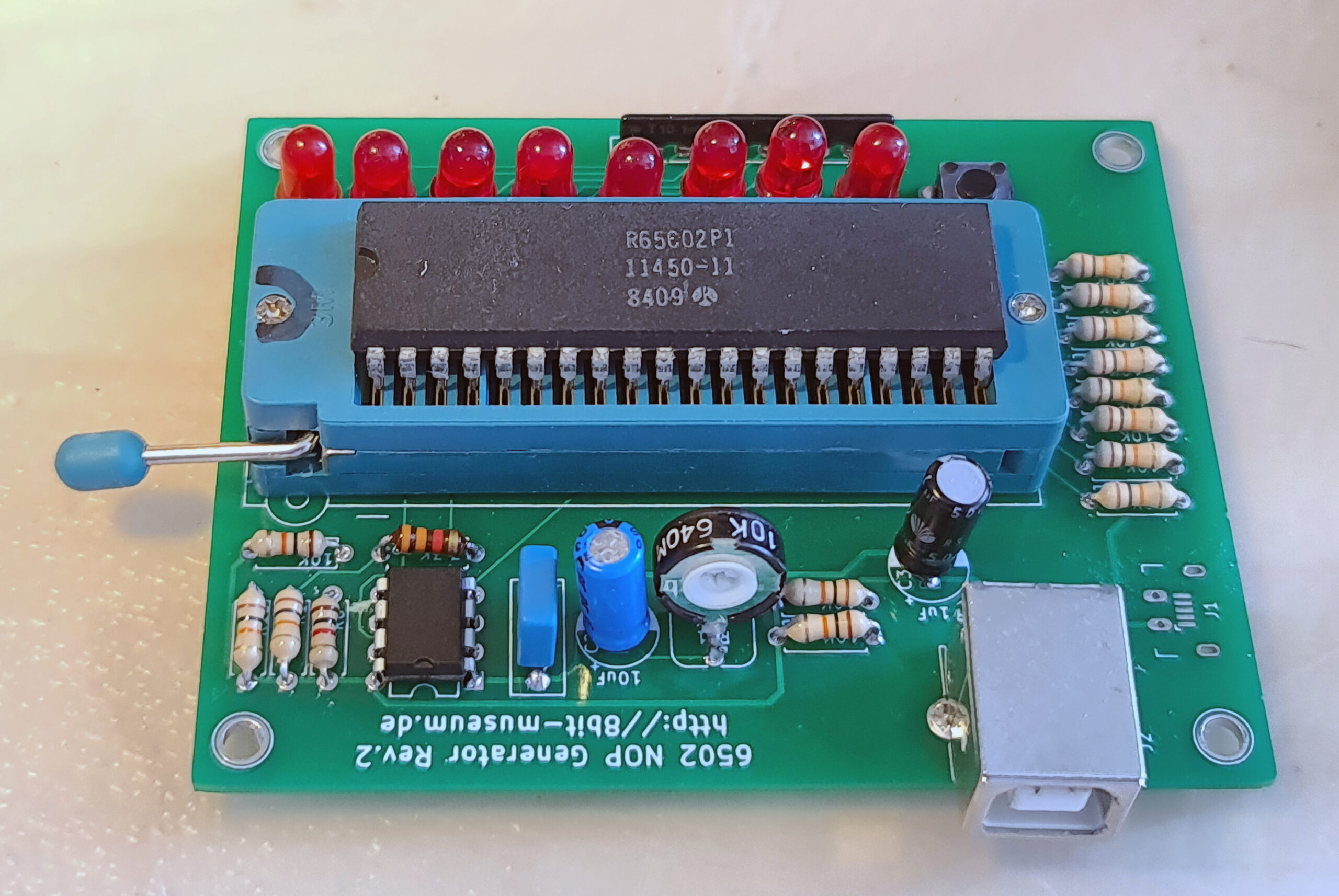
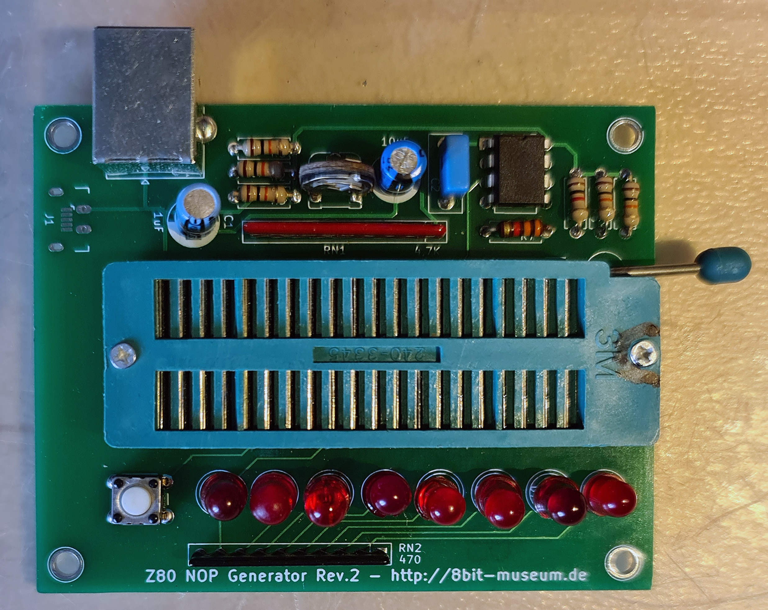
The 6502 NOP generator in action:
The 6502 NOP generator supplies the opcode 0xEA, which corresponds to a NOP for the 6502. After a reset, the 6502 NOP generator starts to count from address 0xEAEA (after a reset the CPU reads the real start address from addresses 0xFFFC-0xFFFD and since this always reads 0xEA, this is 0xEAEA). The LEDs should start counting at 11101010.
It is very nice to see how after the reset the addresses 0xFFFC and 0xFFFD are accessed first (before that a little initialization of the CPU), in order to then count from 0xEAEA (LEDs: FC, FD, E9, E7, EA, E9, FD, [FF] FC, [FF] FD, [EA] EA, EB, EC, ED, EE, EF, F0, F1 .., the upper 8 bits added in square brackets for understanding).
Changes for WDC65C02
While the 6502 NOP Generator has been designed for the 65C02 and 6502 pinout, it can be modified to work with the still available WDC65C02 variant. Differences between the variants are minor but essential:
VPB Vector-Pull output Pin1 must be left open, on the 6502 and 65C02 this is the (second) Ground pin, On the PCB pin 1 is connected to ground, easy to cut track, see the photo below.
Pin 36 BE (Bus Enable) Connect a resistor 10K to VCC. Easy to add on the bottom of the PCB. pin 36 is NC (Not Connected) on 6502 and 65C02.
The latest gerbers on teh site of 8bit-museum have these modifications!
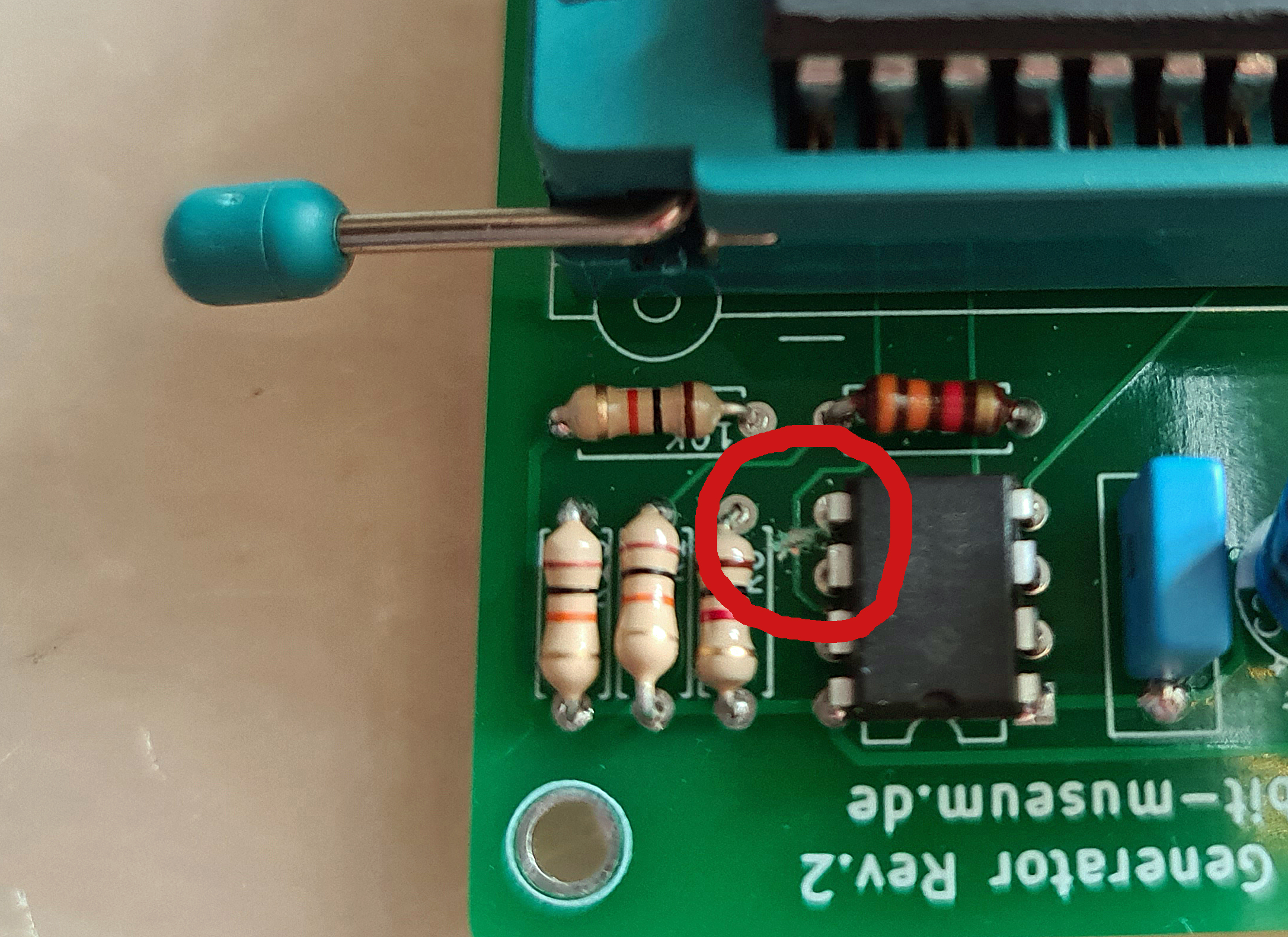
Cut the track on the PCB in the red ring, GND to Pin 1
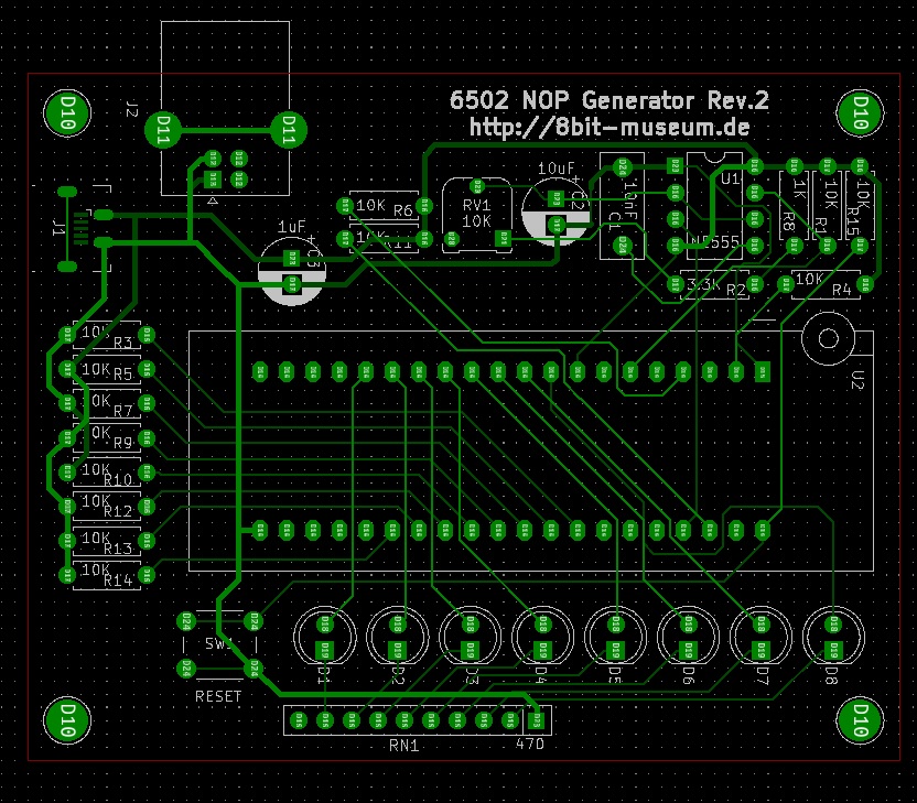
Gerber view in Kicad tool
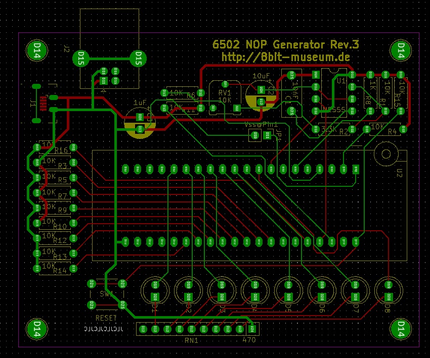
V.3, has a jumper for Gnd on Pin 1 or not, and a 10K resistor on pin36 BE
Z80 NOP tester
When used in a Z80 NOP generator , a Z80 CPU only executes NOP commands (No Operation). The low address lines can be observed with the aid of eight LEDs. If the CPU executes the NOPs, the addresses should be continuously incremented. This does not allow a complete test of the CPU, but at least a quick-n-dirty check.
The NOP generator presented here only works with Z80 CPUs. Since the CPU is clocked very slowly, far outside the specification, it is quite possible that an actually functional CPU does not work with the NOP generator. The way it works is very simple: The data lines are pulled to ground by pull-down resistors, so that the CPU reads a NOP (opcode 0x00) when the memory is read. After a reset, the CPU starts executing these commands from address 0.
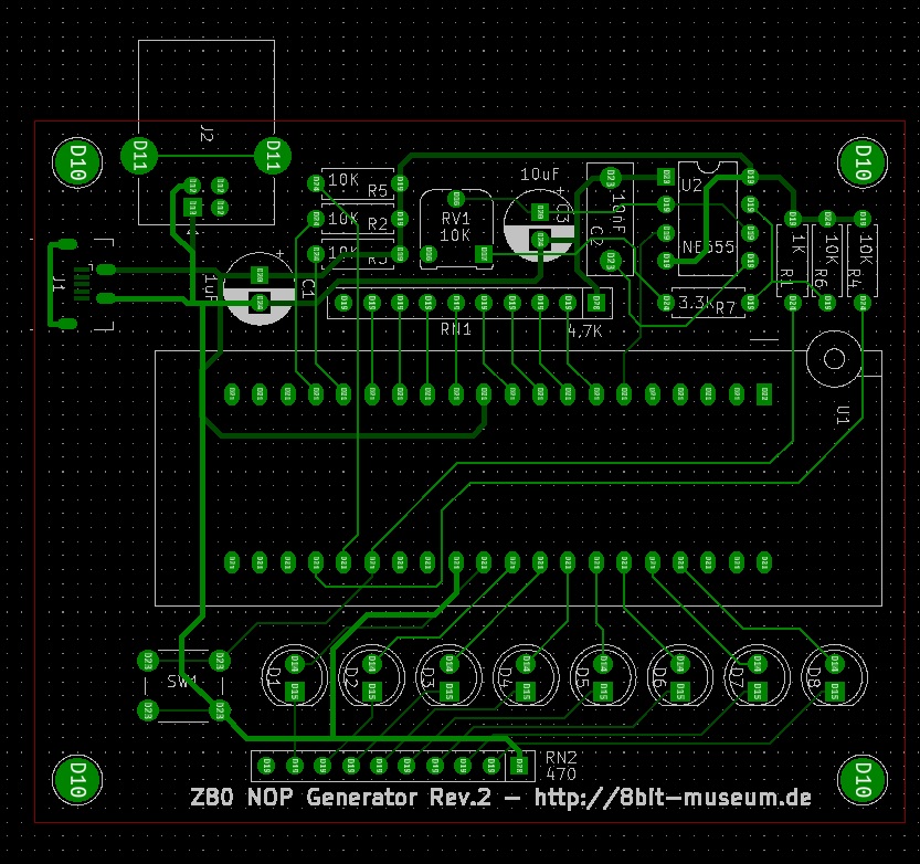
Gerber view in Kicad tool