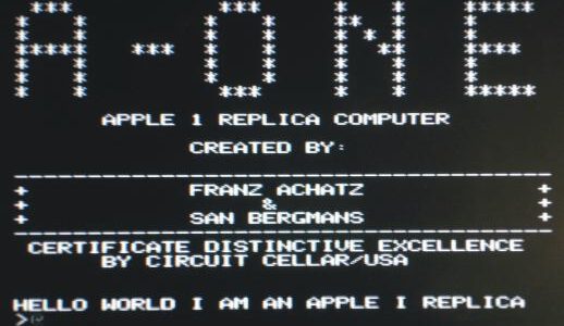
These page is about the A-ONE family of Apple 1 replicas.
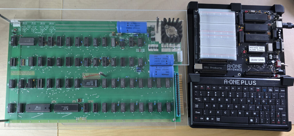
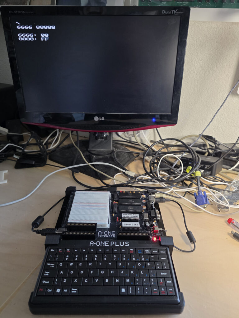
My Apple 1 (replica!) and the A-ONE PLUS
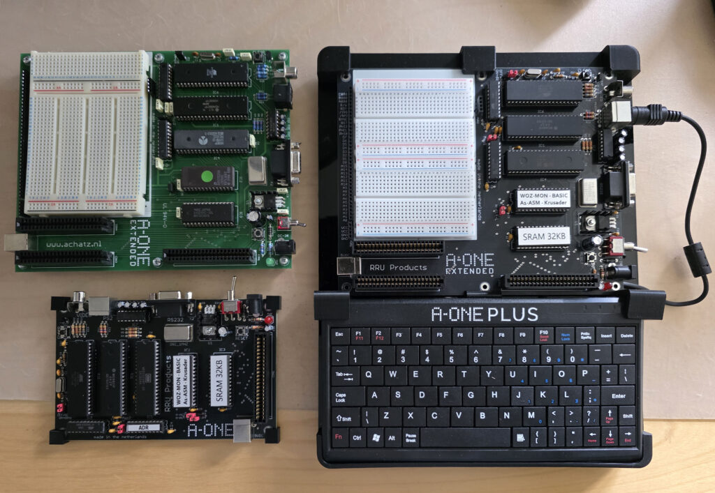
My A-ONE collection
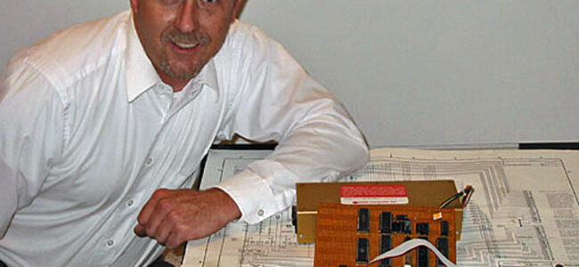
In 2006 Franz Achatz designed the hardware of an Apple 1 replica named A-ONE and sold these for some years. In 2025 Franz continued the product line with updated A-ONE computers.
The A-ONE 2025 products are for sale at the RRU products shop.
The A-ONE was announced as follows:
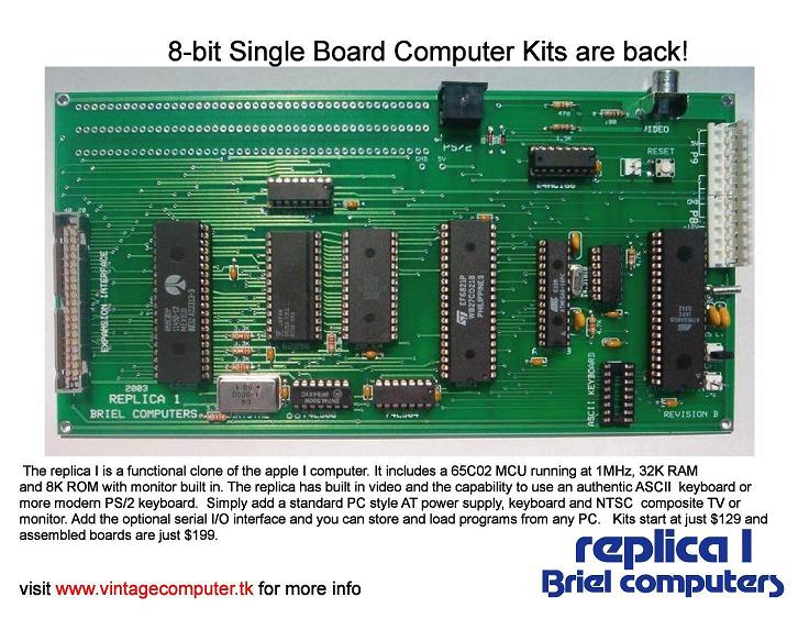
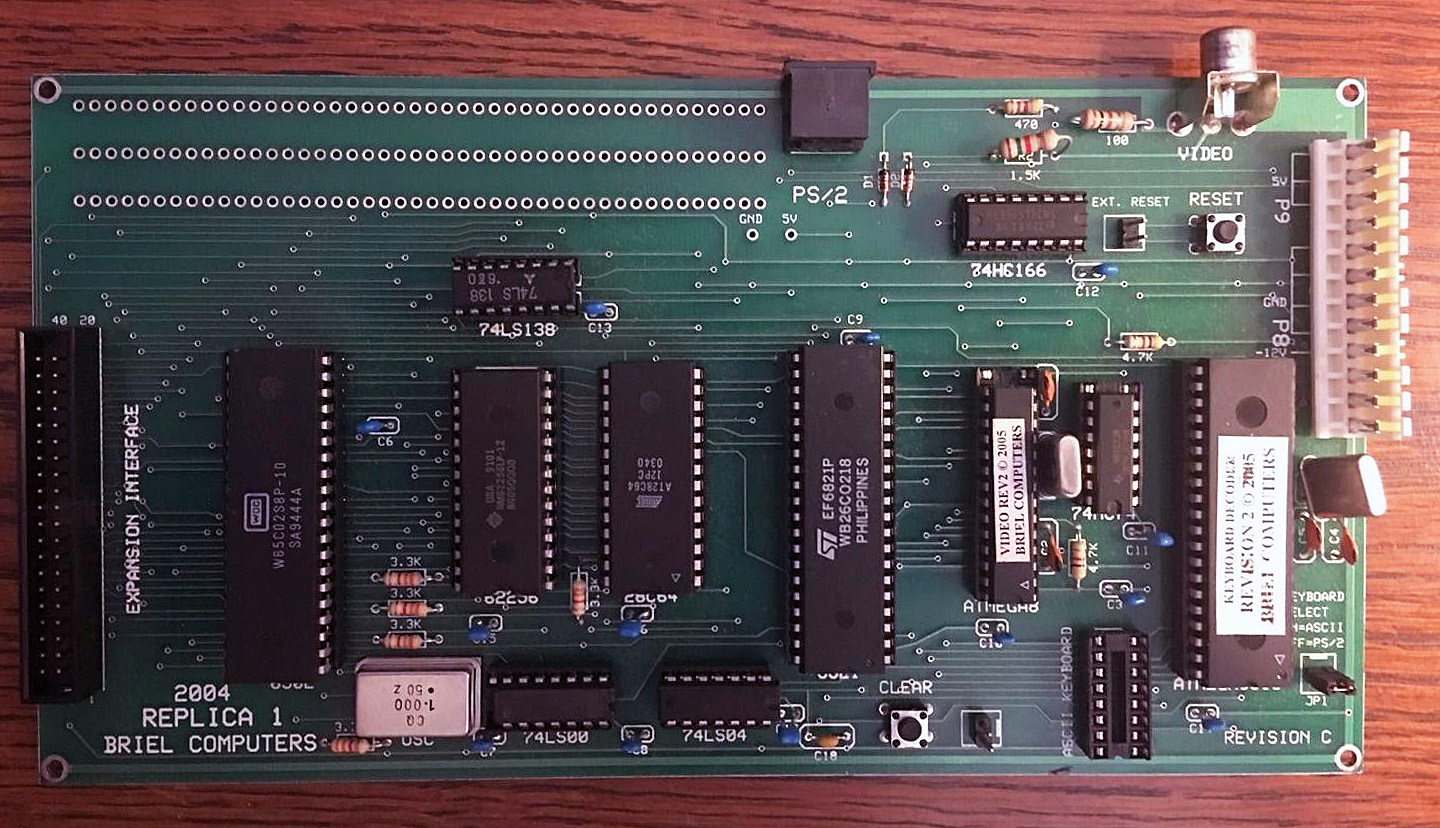
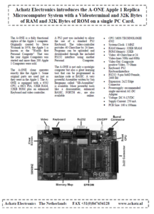
The A-ONE is a compact and high quality Apple 1 replica made and designed in the Netherlands by Achatz Electronics. Similar, but not identical to the Apple 1 Replica 1. Advantages are the small board size and low IC count,, 50 Hz and 60 Hz rock solid video, and the real Apple 1 slot.
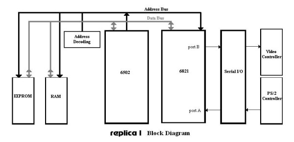
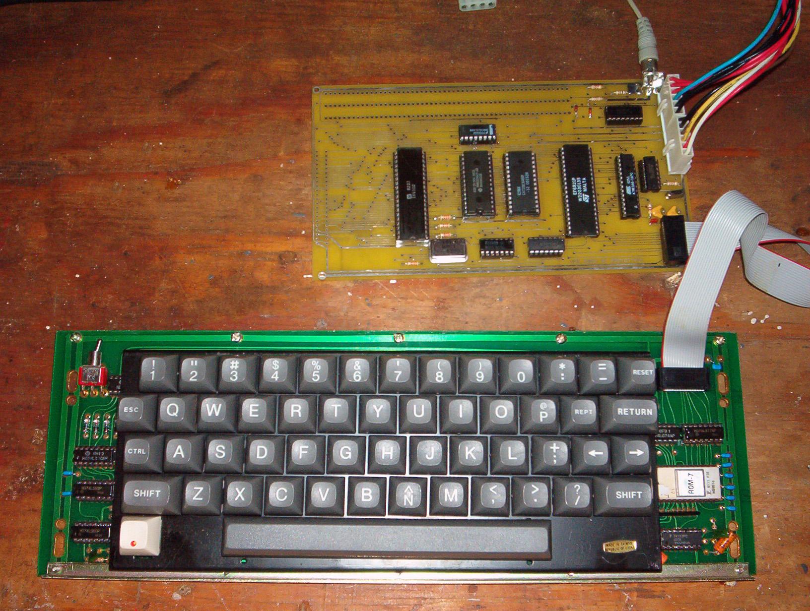
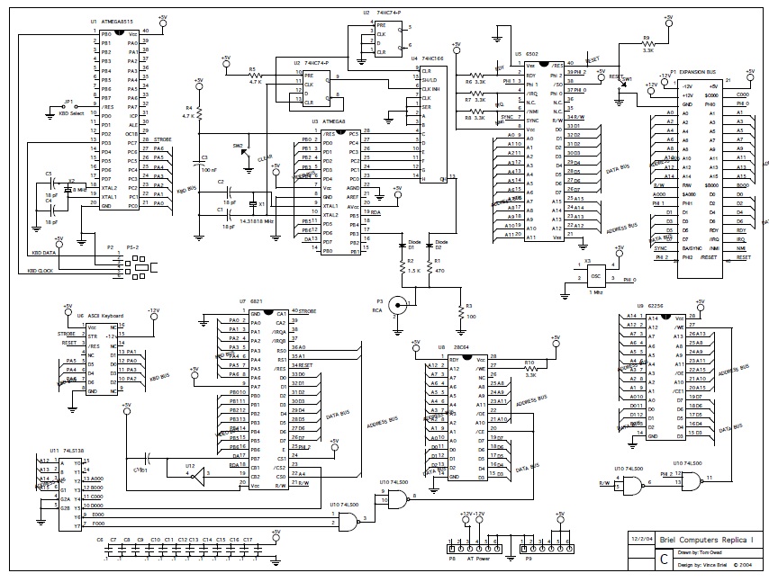
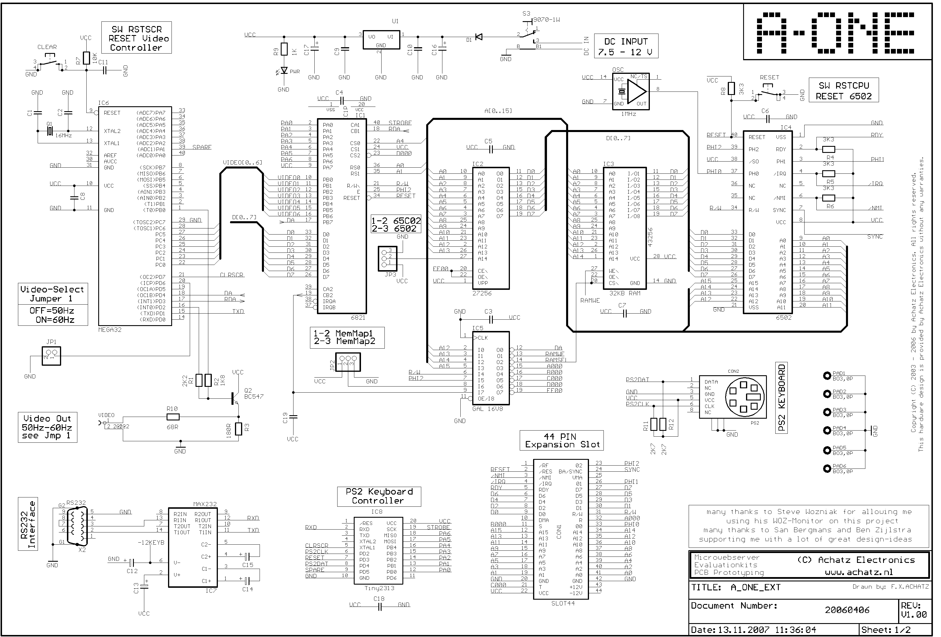
The A-ONE follows the usual concept of Apple 1 replicas. The computer part, the 6502 CPU and 6821 PIA are identical to the Apple 1. The video terminal part is replaced with one or mee modern microcontrollers. In 2006 the Atmel IC’s were the best in the market, so these were chosen for the video terminal.
Franz asked San Bergmans to develop the firmware for the video terminal part with an ATMega32 . And Ben Zijlstra for the PS/2 interface with a ATTine2313.
San Bergmans also developed a subset of his big PC based SB Assembler, the A1-Assembler, that runs on the 6502.
In 2006 I acquired the A-ONE EXTENDED. In 2026 the A-ONE PLUS and standard board were added tot he family.
The A-ONE family in 2006
- A-ONE Standard board
- A-ONE EXTENDED
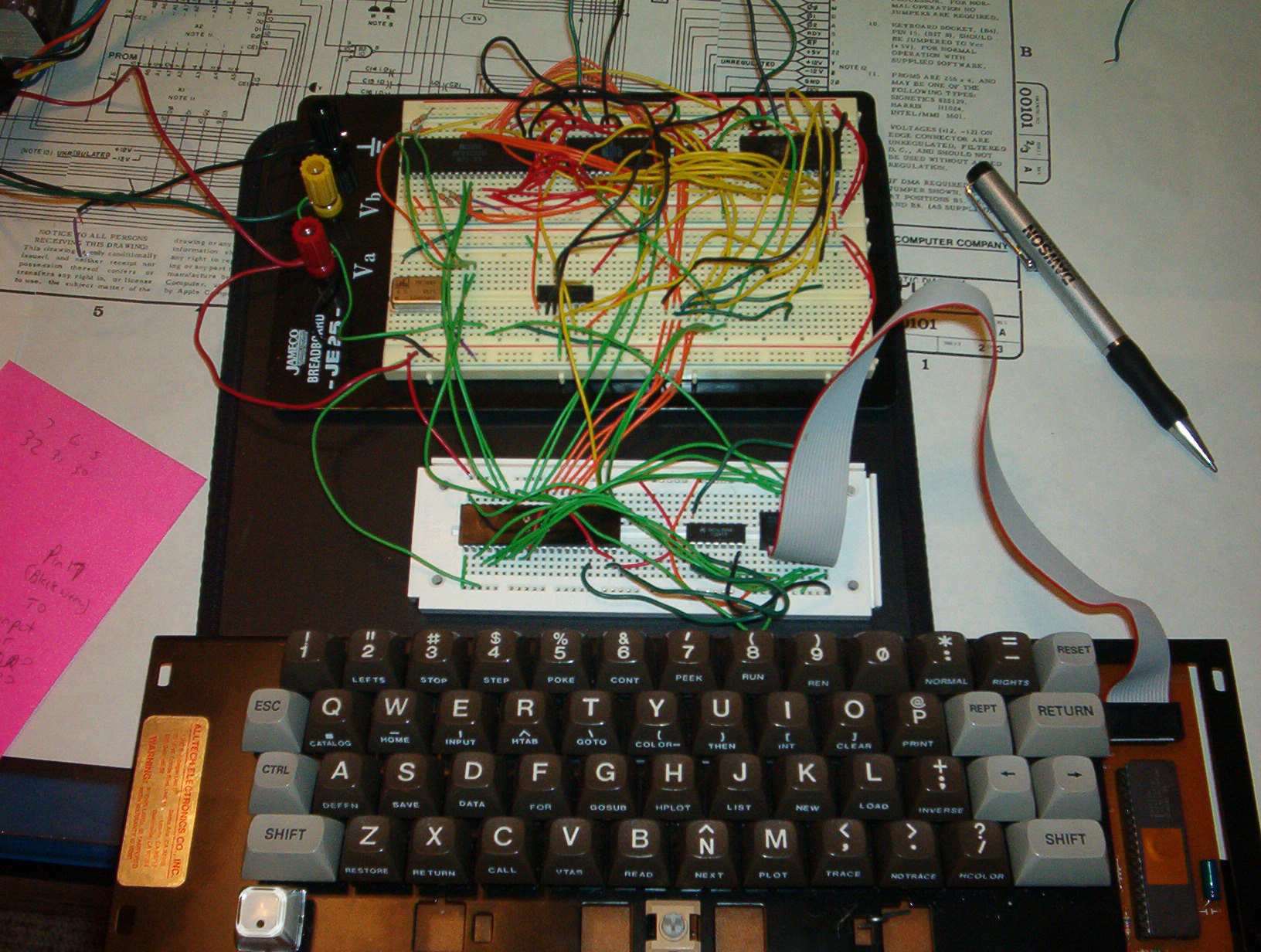
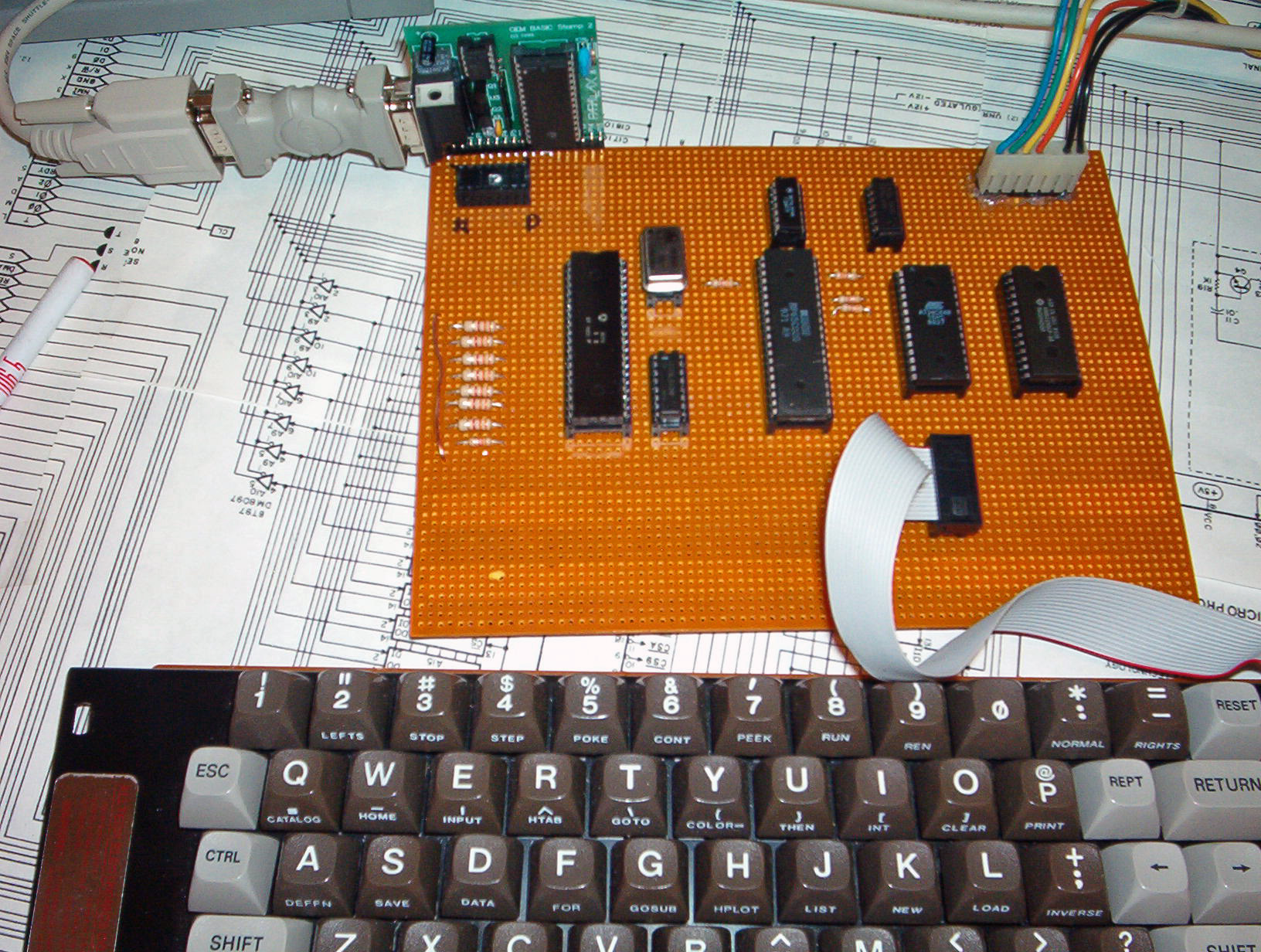
- A-ONE Prototype board
- A-ONE Prototype board with breadboard
The A-ONE family in 2025
- A-ONE standard board
- A-ONE EXTENDED
- A-ONE PLUS
- A-ONE Cassette Interface
- A-ONE Prototype board
- A-ONE Prototype board with breadboard
Specifications of the A-ONE
All A-ONE computers share the same design, firmware and software.
- CPU: MOS TECHNOLOGY 6502 (65C02 supported)
- System-Clock: 1 MHz
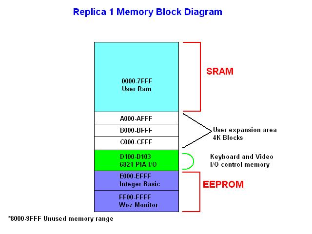
- RAM Memory: 32KB SRAM
- ROM Memory: 32KB (64KB EPROM, selectable are two banks)
- Video: 40 Chars/line at 24 Video-lines 50Hz and 60Hz
- Video Out: Composite positive Video, 75 Ohms
- Keyboard: PS/1 Keyboard interface
- RS232: 9-pin SubD Female, 2400 Bd
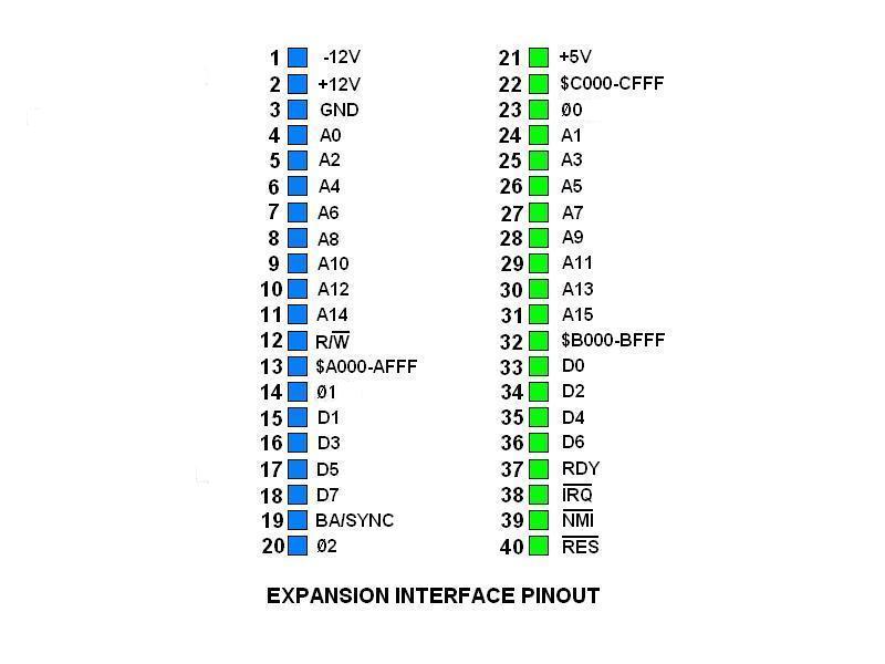
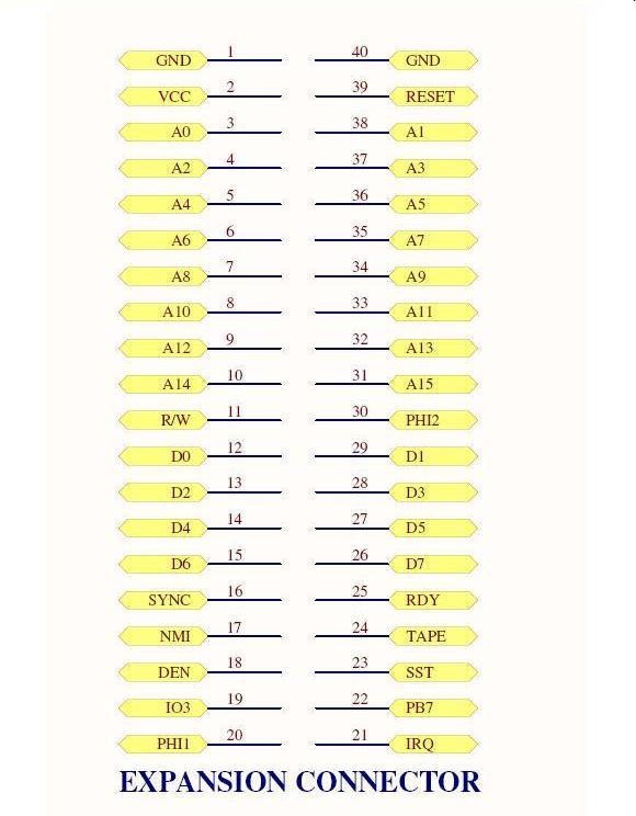
- Expansion: 2×22 Edge Connector (3x for EXTENDED and PLUS
- Powersupply single universalAC-DC Adapter DC 9-12VDC
Supply Current: 250 mA - 2025 versions: USB connector as alternative power supply
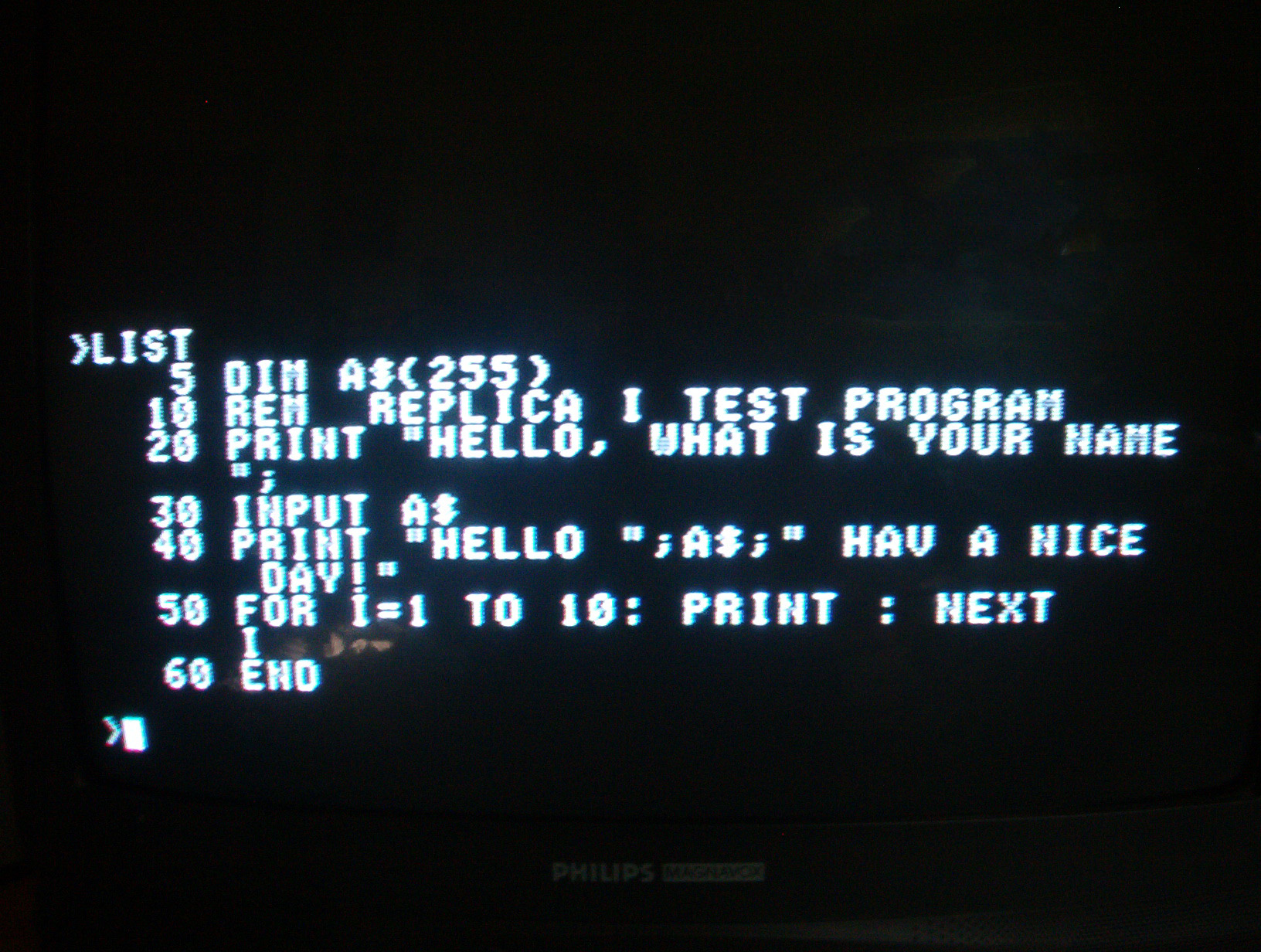
- Software
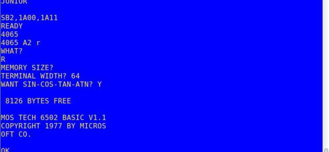
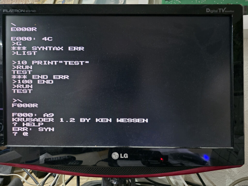
WozMON monitor
Apple 1 Basic
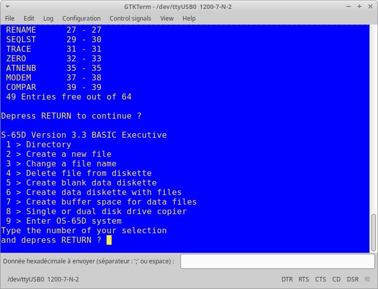
Krusader 1.2 Assember/Editor
A1-Assembler - Jumpers for:
JP1: Video 50/60Hz
JP2: MemoryMap (see Manual)
JP3: H-A14 = 65C02 CPU, A14-L = 6502 CPU
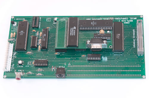
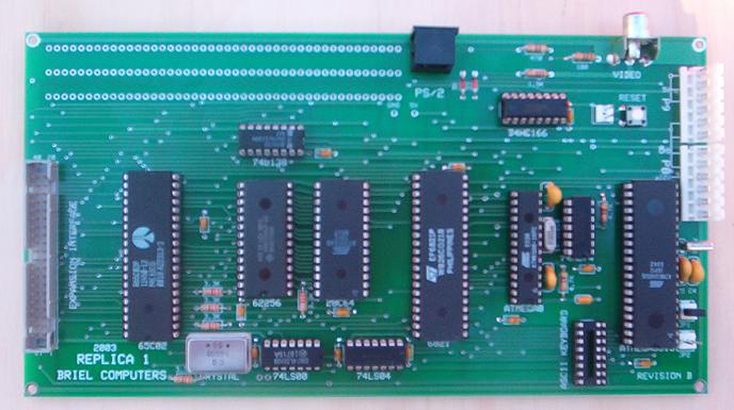
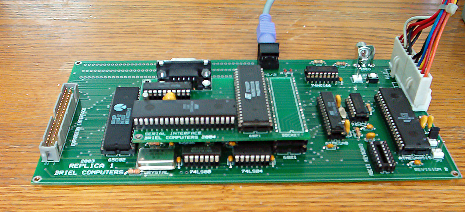
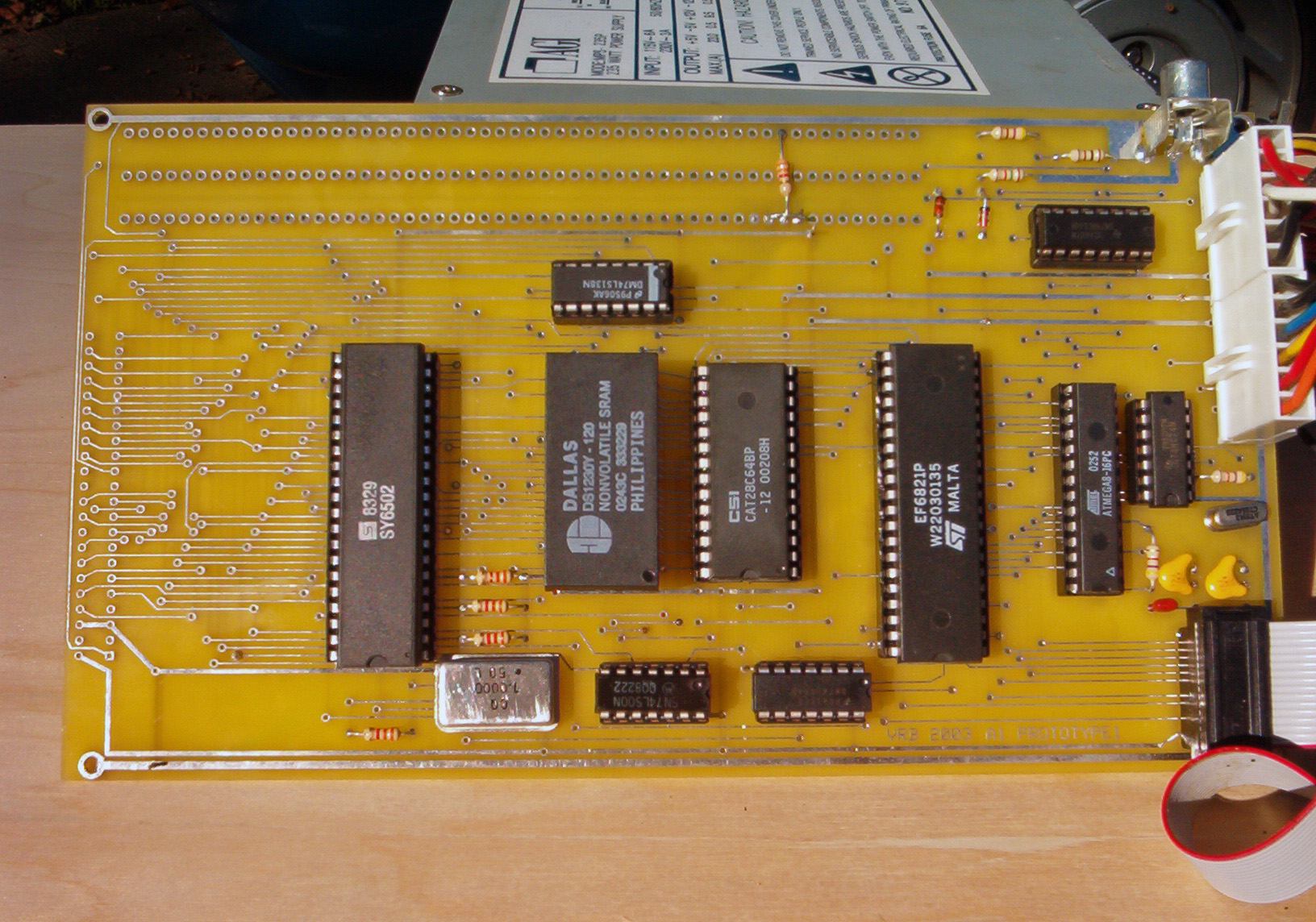
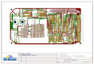
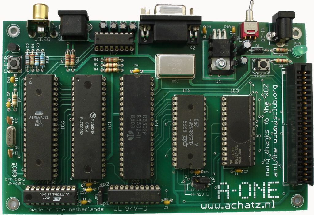
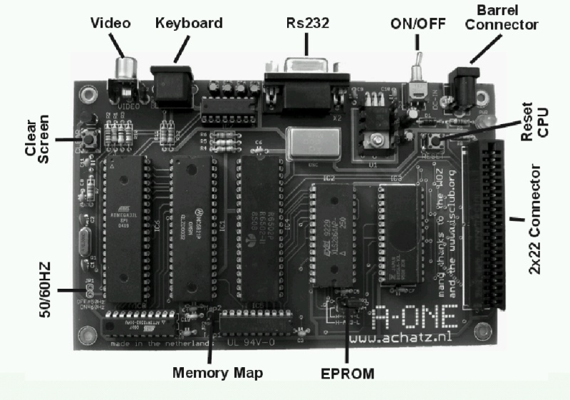
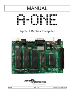
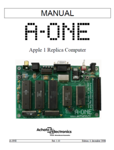
A-ONE 2006 standard board
This is the first edition of the A-ONE. All other A-ONE computers share the same design.
A compact 100x160mm PCB, professionally made.
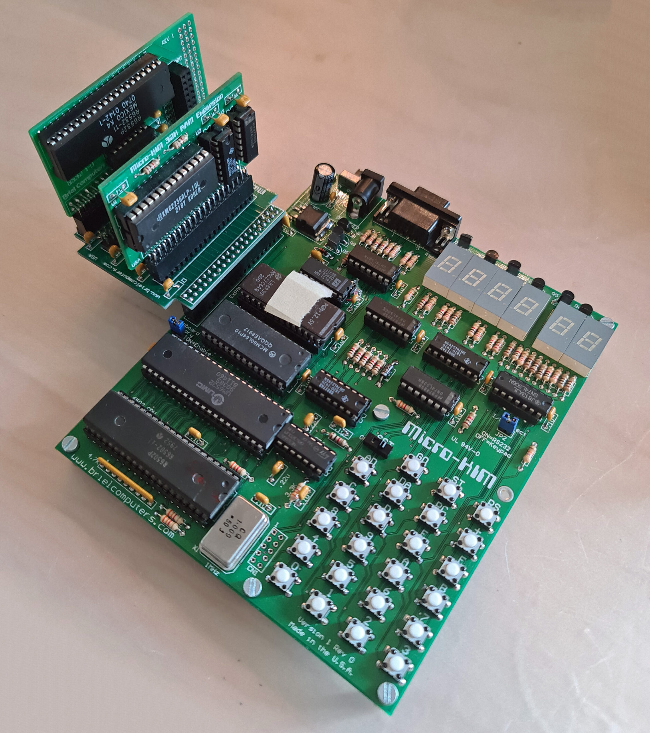
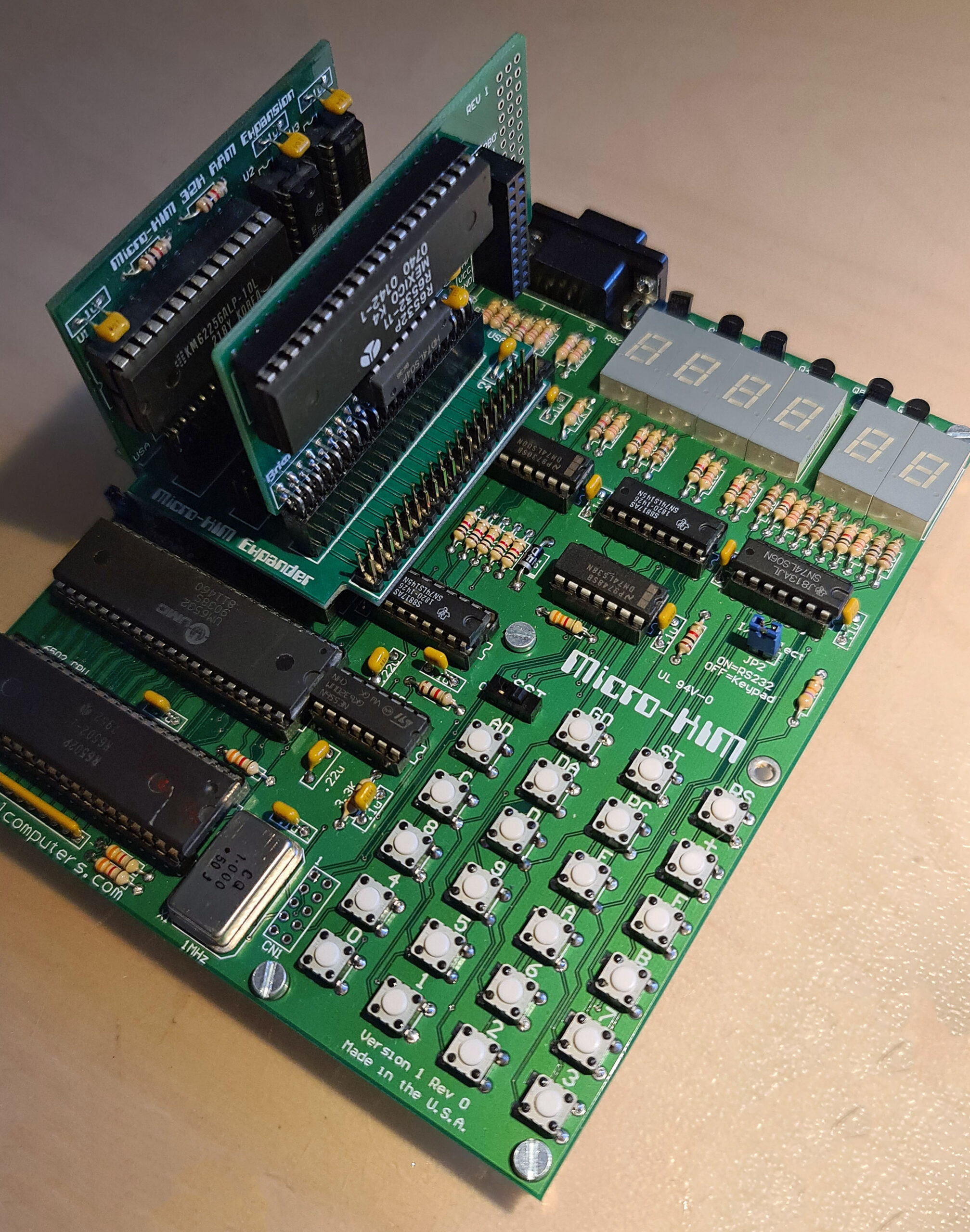
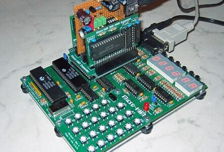
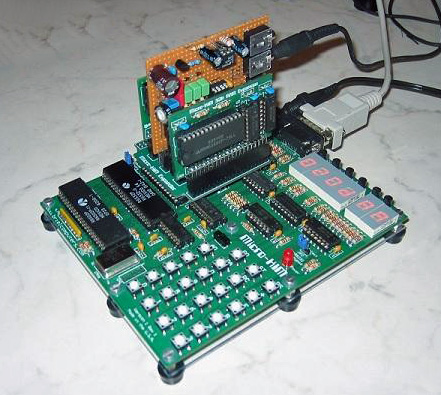
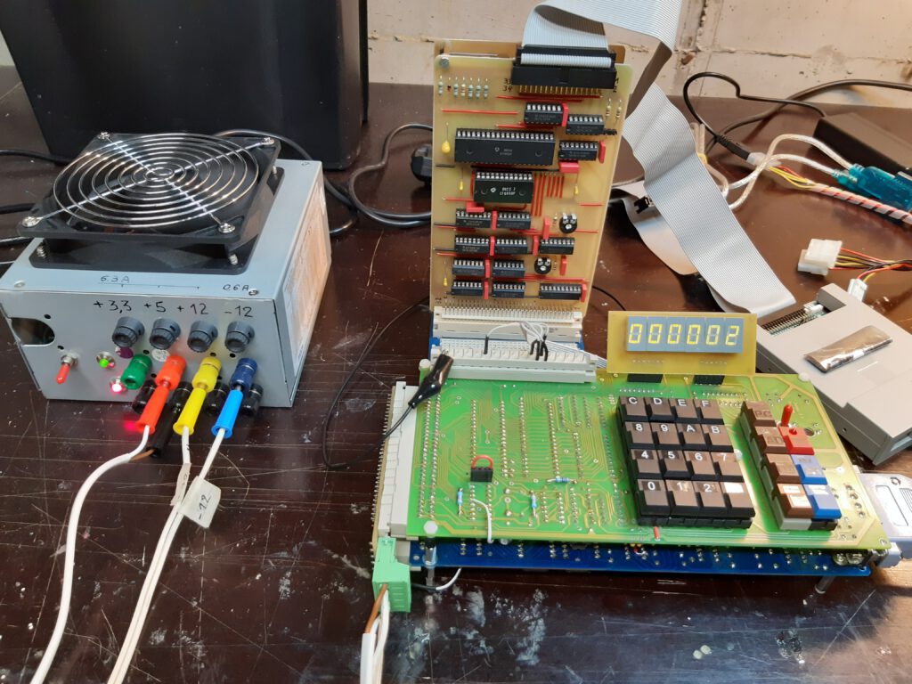
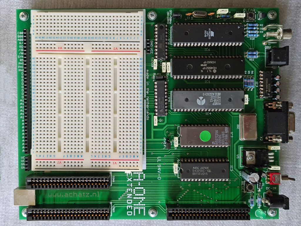
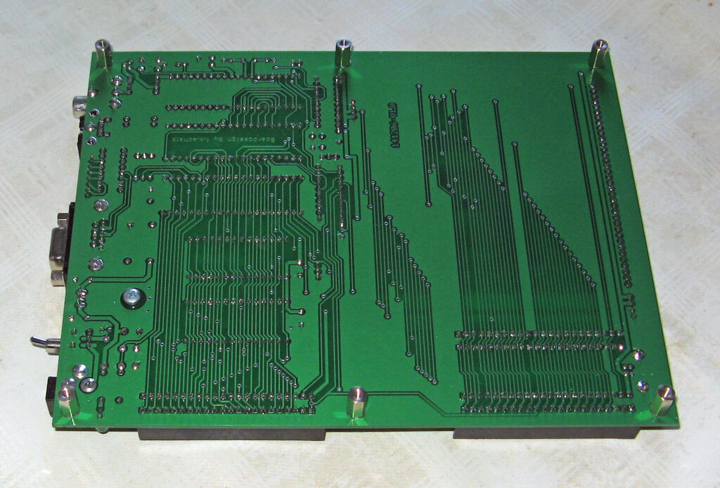
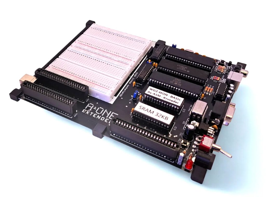
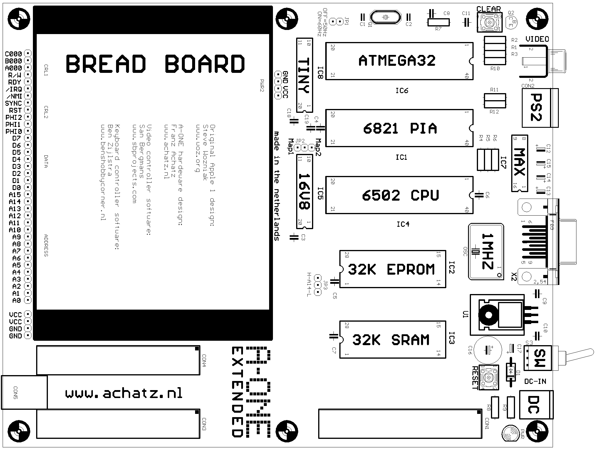
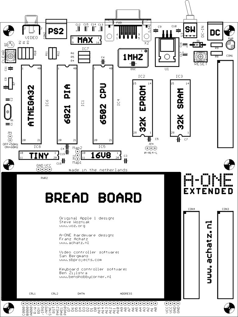
A-ONE 2006 EXTENDED
This larger PCB adds a breadboard area to the A-ONE, access to all the relevant signals in the system and three expansion slots.
And with the extra USB powersupply connector.

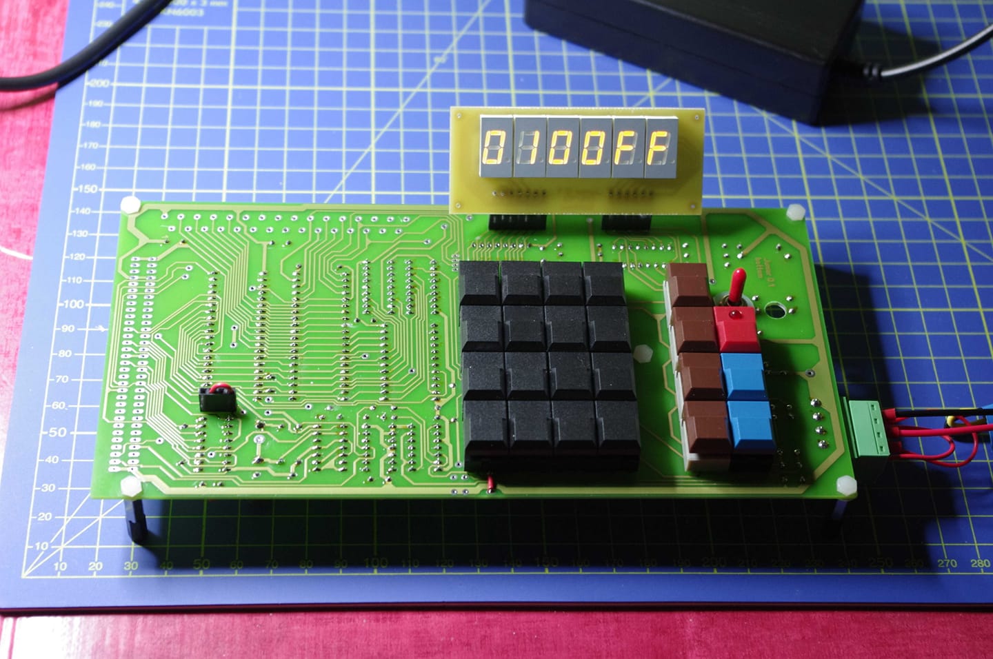
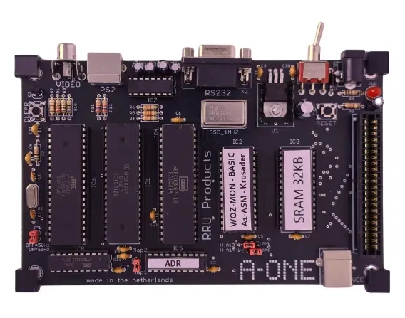
A-ONE 2025 Standard board
A remake of the standard board. Black PCB, USB power connector added. 3d printed supports.
A-ONE 2025 EXTENDED
Also a remake of the EXTENDED version. Same specifications, black PCB, 3d printed supports.
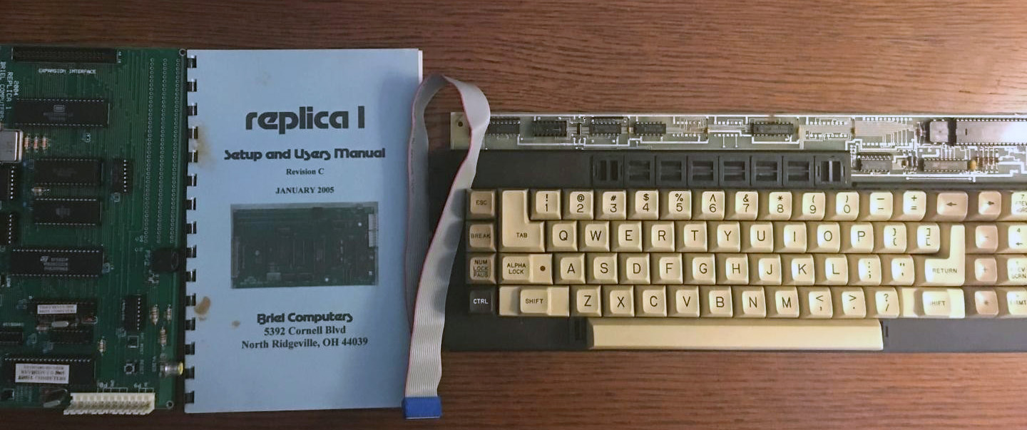
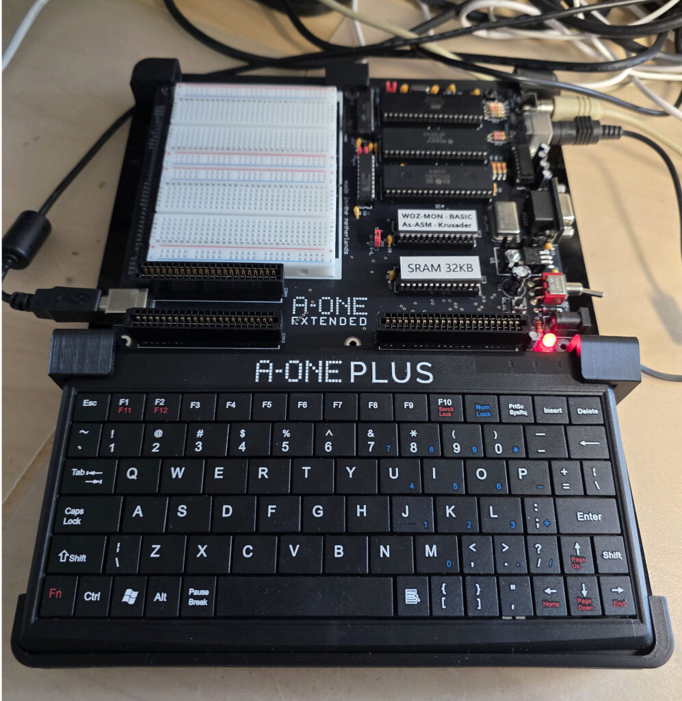
A-ONE 2025 PLUS
A new family member. An A-ONE EXTENDED with a mini PS/2 keyboard placed on a plexiglas bottom, with 3d printed supports.
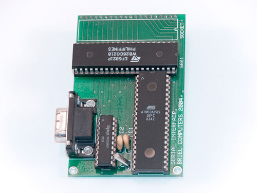
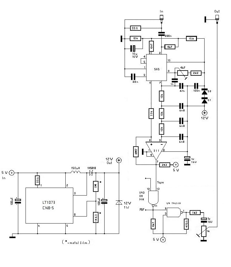
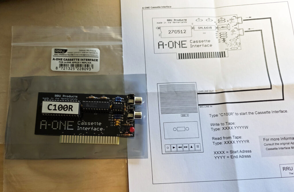
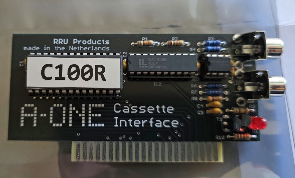
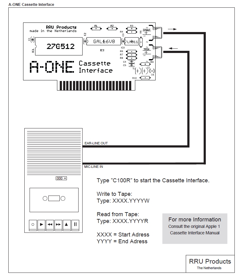
A-ONE Cassette Interface
The A-ONE cassette interface is compatible with the ACI Apple 1 casssette interface.
With different components, like a GAL16V8, a 27512 EPROM and a LM311 comparator. The software on the EPROM interface, at c100, behaves identical.
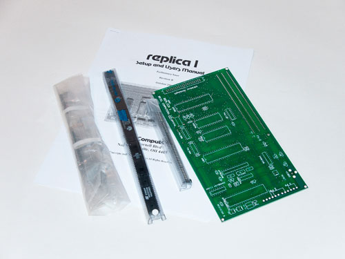
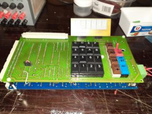
A-ONE prototype boards
Working with the A-ONE extended becomes even more a pleasure with the prototype boards sold by Achatz Electronics.


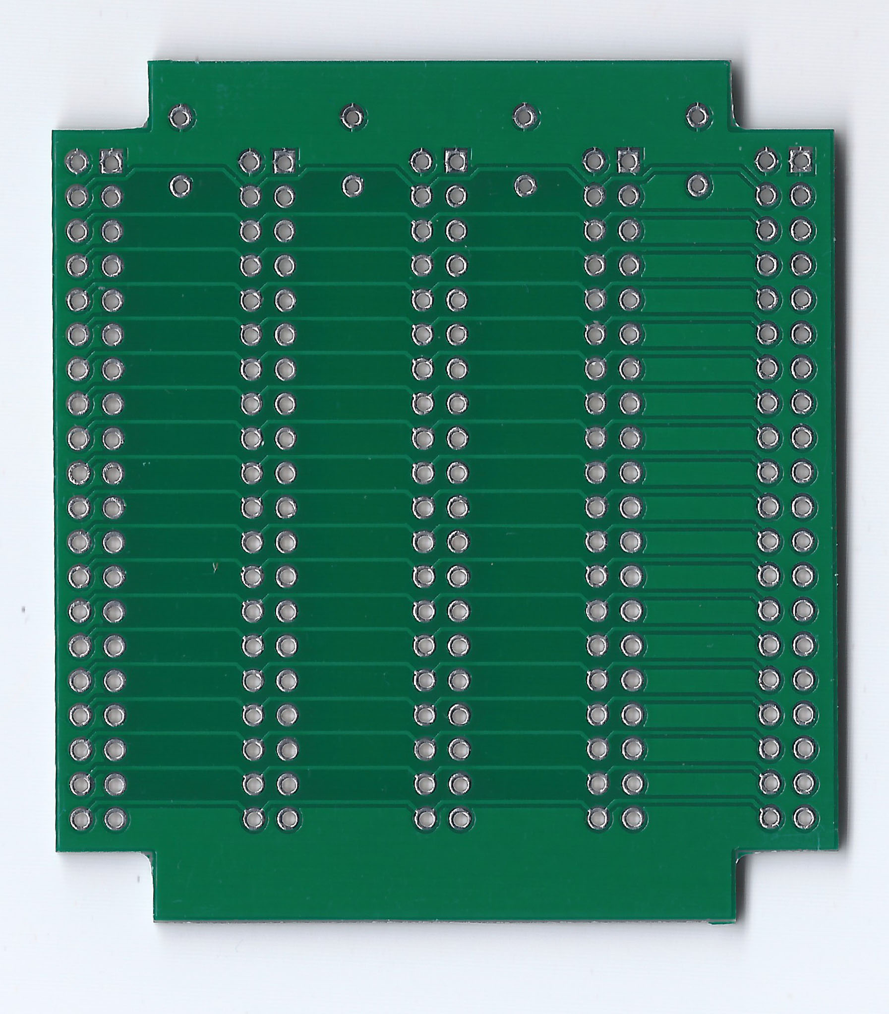
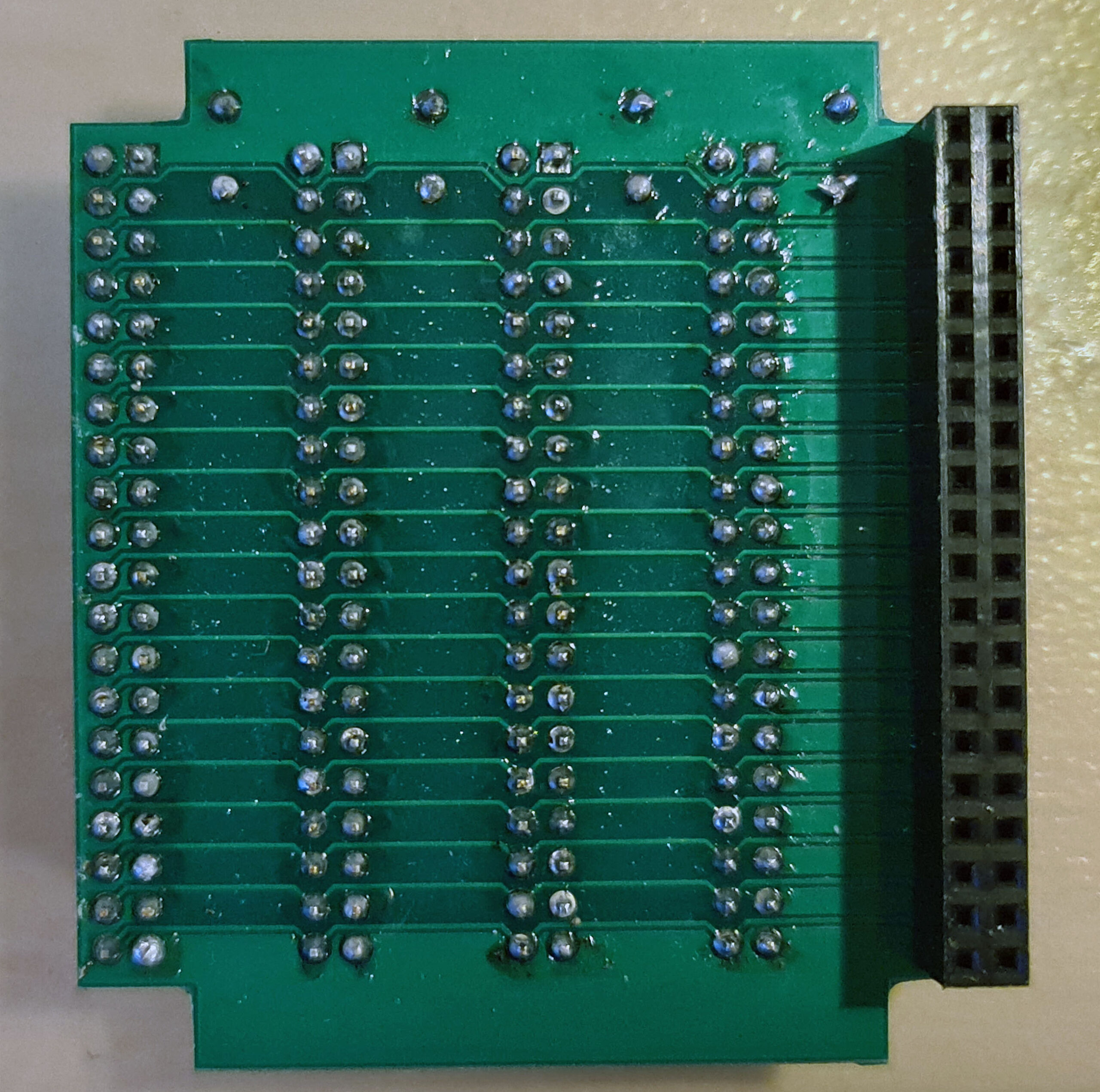
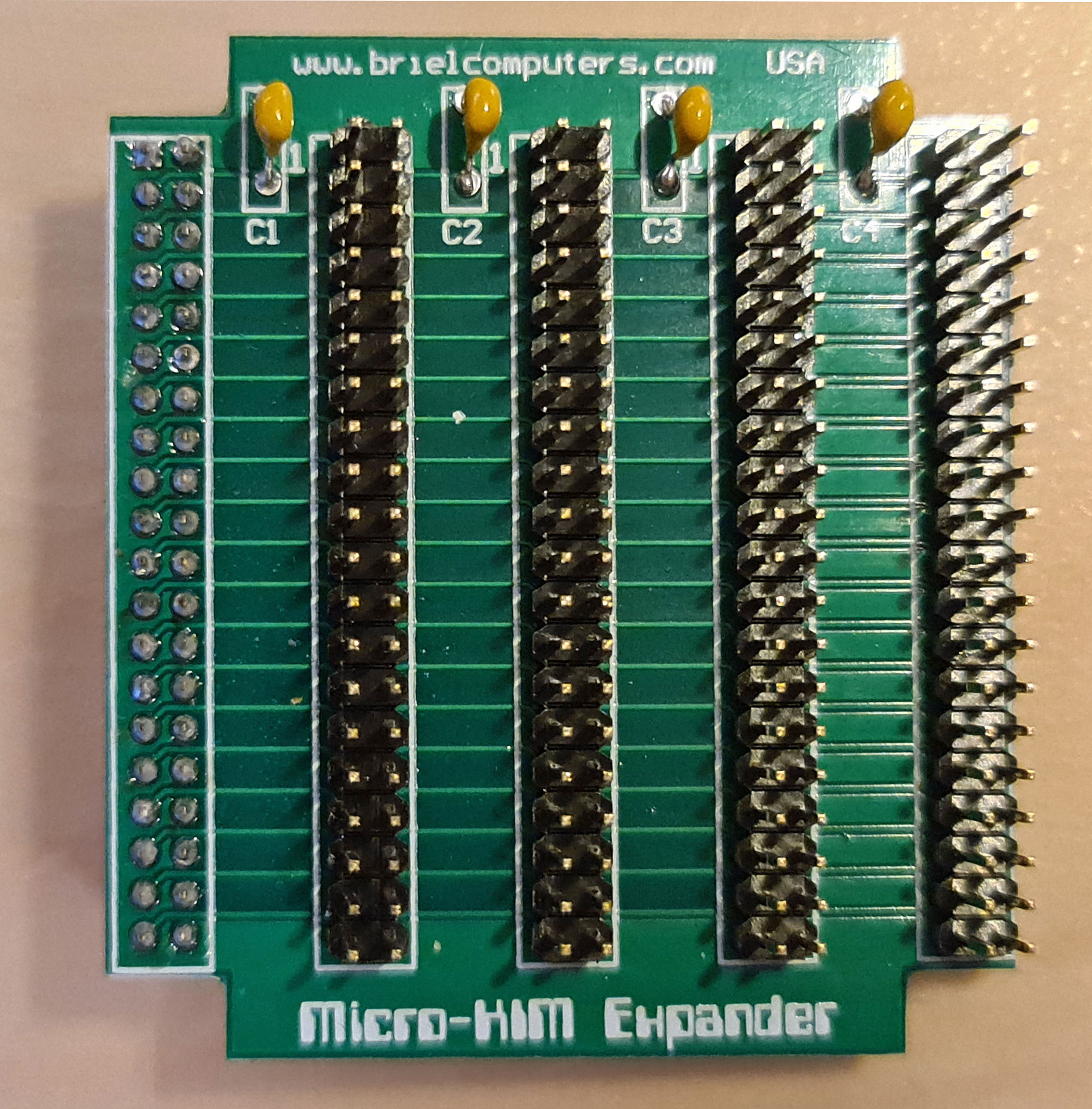
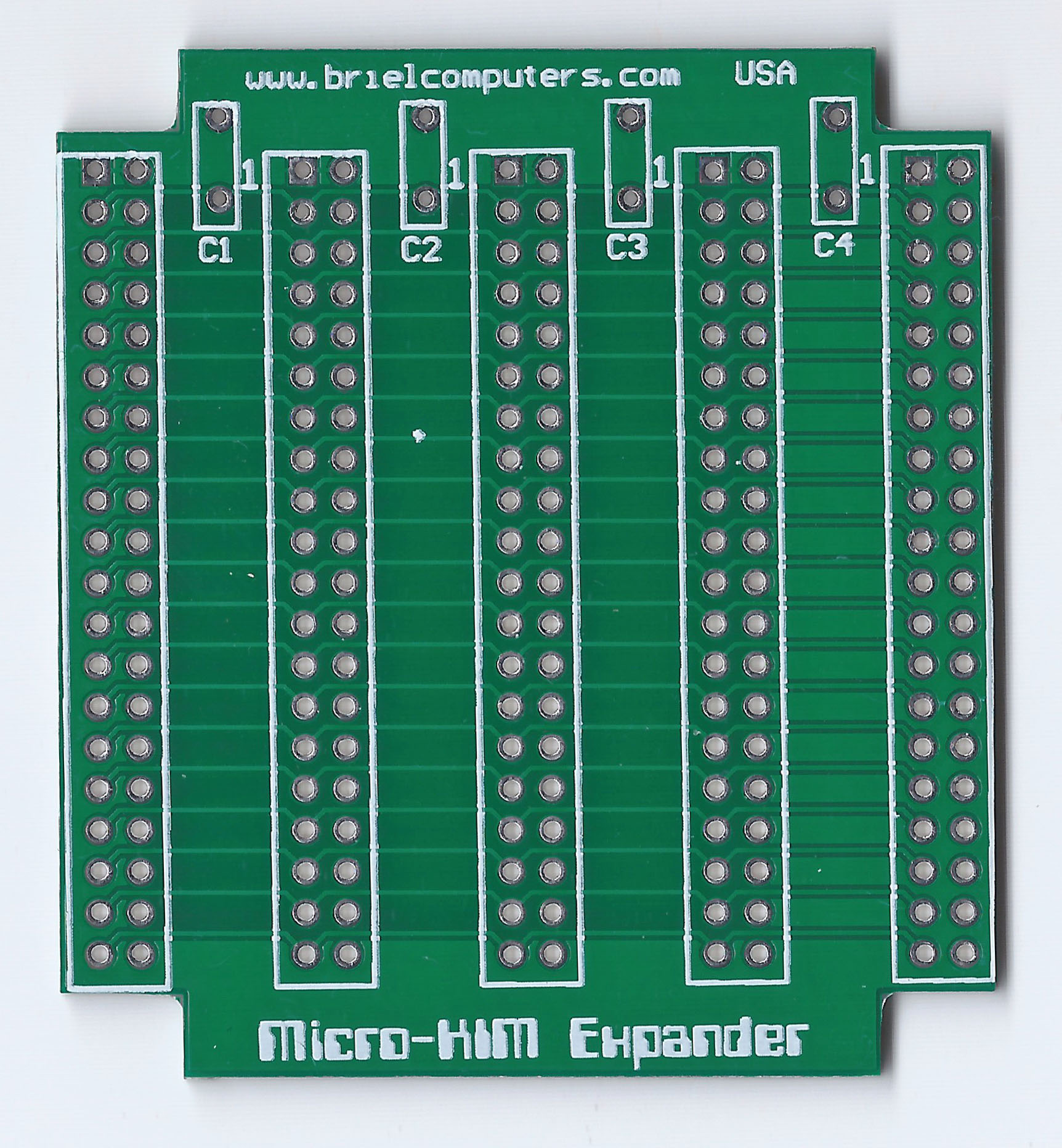
Since the Apple 1 connector is electrical equal to the A-ONE but of different size, it is possible to use the Apple 1 and Replica 1 extensions, such as the CFFA1 and the multi-I/O board on the A-ONE. It will need a A-One slot to Apple 1 slot interface, one on one, perhaps via one of the prototype boards.
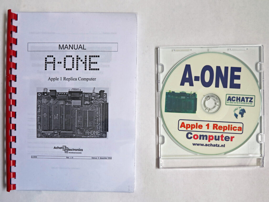
A-ONE information

A-one
A-one extended

A-one extended
 |
A-ONE manual 1.0 |
 |
A-ONE manual 1.10 |
|
A-ONE manual 2025 |
 |
Elektuur announcement |
 |
A-ONE flyer |
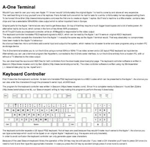 |
A-ONE terminal description by San Bergmans |
SB-Projects, San Bergmans’ description of the working of the Apple 1 and all about the A-ONE
Downloads
- Firmware: sources, hex files, ROM
- Software: Basic programs, Microchess, Krusader, A1-Assembler by San Bergmans and more