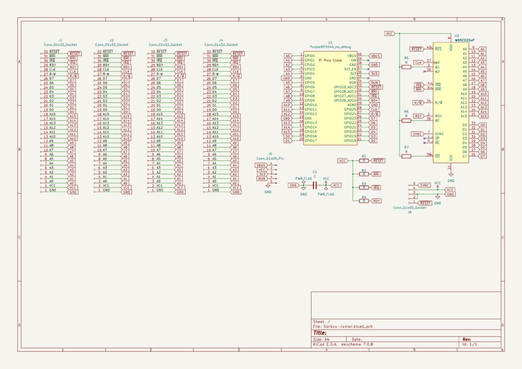
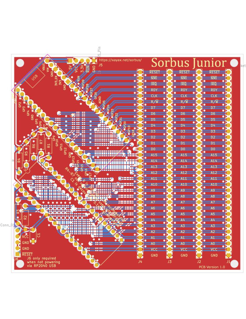
The hardware of the Sorbus computers could not be simpler. Designed with care to be as flexible as possible, fully programmable in behaviour, with a small footprint and at very low cost.
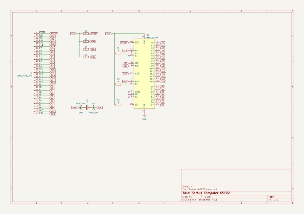
Two components: a 6502 CPU and the ‘purple’ RP2040 board.
Part 4 is about software, like Wozmon.
The design is open source hard- and software. Have a look at the Sorbus github page for the details. All information here is based upon this.
The goal of the Sorbus system is to play with the 6502 as simple and affordable as possible. It can run many serial terminal based 6502 programs, such as the Apple 1 Wozmon monitor, or the TIM monitor with a system clock over 1 MHz or special programs to study the behaviour of the 6502, step by step at very low clock rates (with a 65C02, the CMOS variant is a static design)
The Sorbus computer is 6502 based, including the 65816. The RP2040 serves as fully programmable peripheral for clock, reset, NMI/IRQ, RAM, ROM, serial I/O.
- A 65XCPU, the CMOS variants will work best, since they are static and can run at very low clock speeds
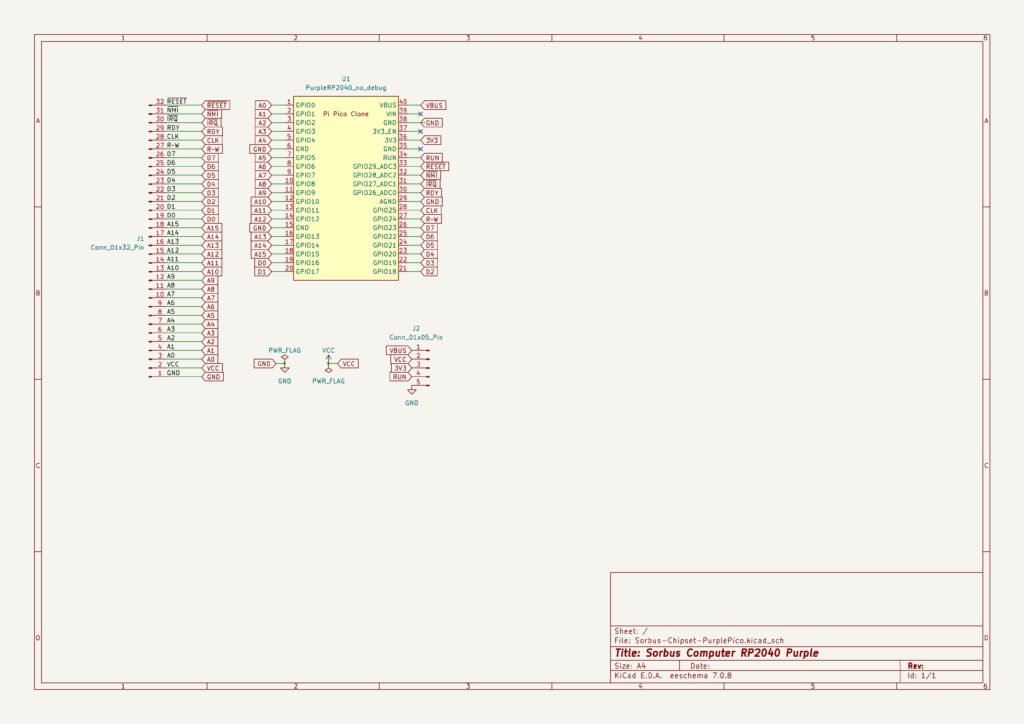
- A Raspberry Pi Pico RP2040, on the ‘purple’ board, which you can buy e.g Chinese sites, exposing 30 GPIOs, more than the official Pico.
- A backplane with the 6502 bus, all relevant signals under control of the RP2040.
The 30 GPIOs of RP2040 on the ‘purple’ board of the available make it possible to control any 6502 CPU.
SvOlli has designed two systems, identical in behaviour, around the Sorbus concept: the larger Sorbus system with a backplane with 6 slots with a 6502 CPU card and a RP2040 card. And the Sorbus Junior, with a backplane with 4 slots and CPU and RP2040 on the same PCB.
A backplane, 32 pin connector
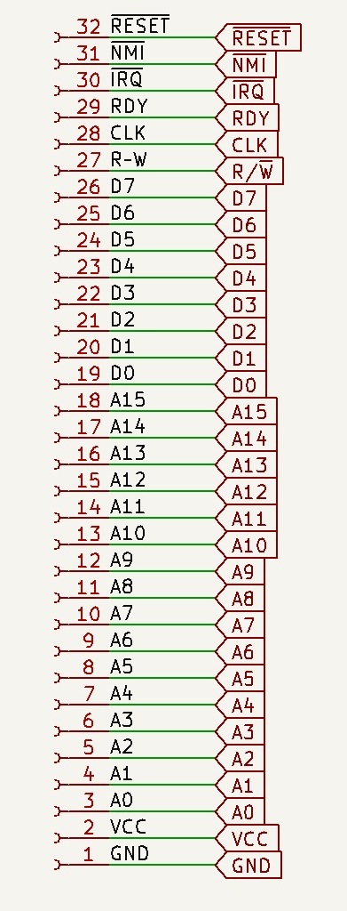
The RP2040 has complete control with its 30 GPIOs of the 6502, all address and datalines (24), CLK, Reset, NMI, IRQ, RDY, R/W (6), total 30. GND and VCC add up to 32, the number of pins on a backplane slot.
Note that is a very basic and limited backplane. Notable missing signals are SO, Phi1. And for the WDC65C02 BE, VPB and MLB are missing. In practice most expansions can be made with this backplane, like I/O. How this conflicts with the RP2040 in control needs to be seen.
5 V tolerance
A 6502 CPU require 5V for power and all signals are at 0 or 5V level. Only the WDC65C02 runs at 3.V or 5V.
The GPIO’s of the RP2040 are officially not 5V tolerant. Only if power is fed into the GPIO part of the Pico, it can tolerate 5V it seems.
Since the whole system is driven by one power supply, coming of the USB connector of the RP2040, it might be safe, but no guarantee. SvOlii has not seen problems with this in his systems.
When you have external devices feeding into the Sorbus, and those are powered on and the Sorbus off, you are in trouble.
There are several jumpers (J5 on the Sorbus Junior, J2 on the Sorbus RP2040 Chipset board) available to feed the 6502 with +5V (called VBUS on the RP2040, directly connected to the USB connector.
6502 variants
The Sorbus accepts many 65X02 variants without jumpers. Not used outputs are left unconnected, unused inputs (SO, Phi1) are tight high with a 3k3 resistor.
Pinout differences: BE is available on the WDC65C02, not connected on all other. Has a pullup 3k3 to enable the BUS Enable.
The 6502 has two GND (Vss) connections on pin 1 and 21. On the WDC6502 pin 1 is the VPB output signal and is left unconnected on the Sorbus.

