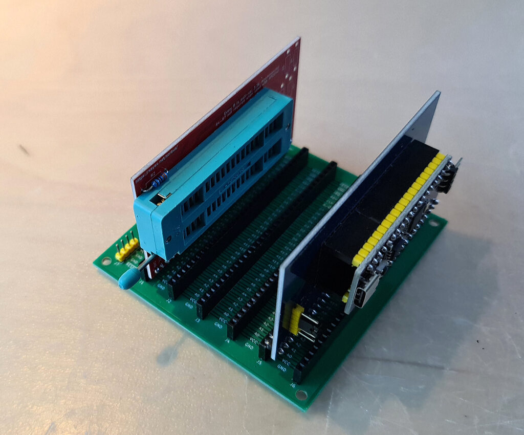
Soldering the PCBs
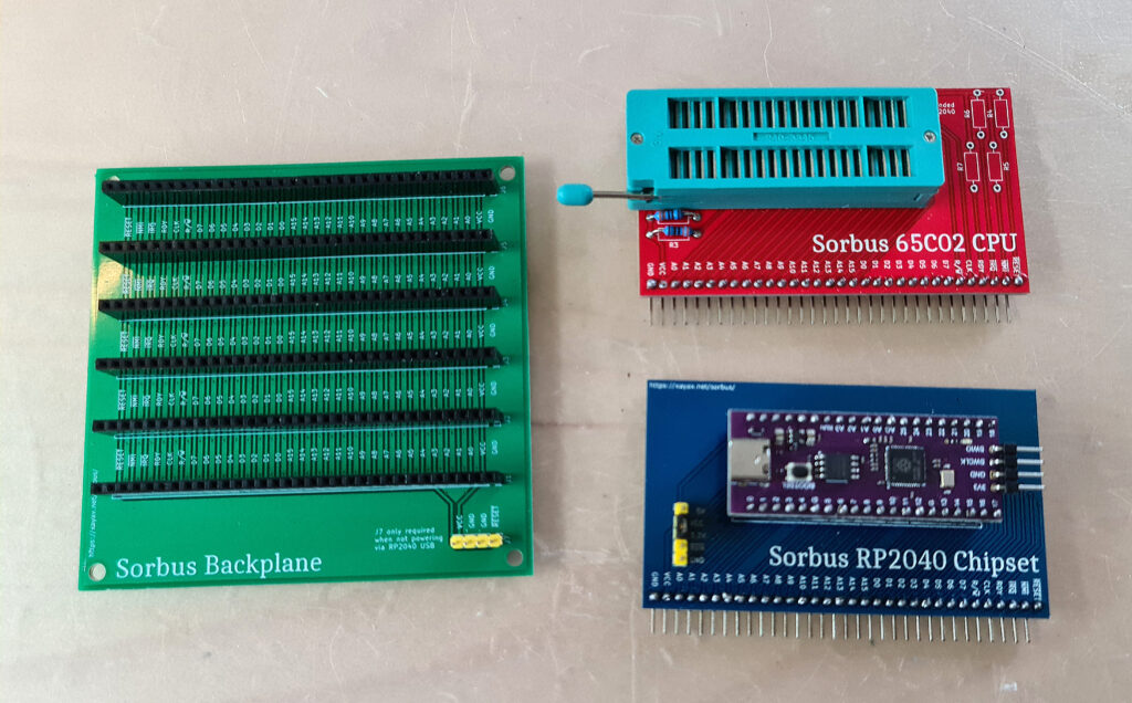
I got from Sven PCBs for the Sorbus and the Sorbus Junior. It took an afternoon to solder all parts, the bus connectors took most of the time (10 x 40 pins!).
In part 1 the Sorbus computer concept was introduced, designed by SvOlli.
Part 3 is about taking a look at the hardware.
I decided I wanted to be able to exchange all parts, you never know what might happen during the experiments.
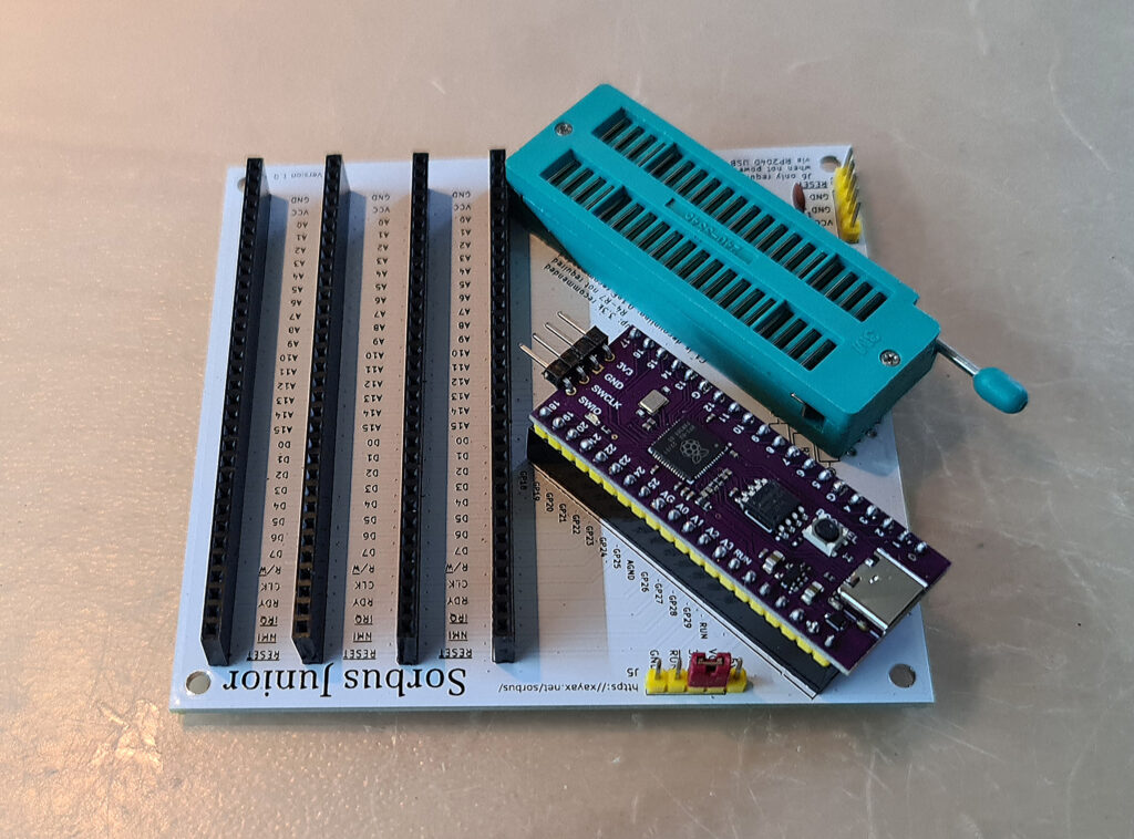
To be able to exchange the CPU’s the IC socket is replaced with a ZIF socket. Sven is working on supporting many 6502 variants, and that will be more fun with a ZIF socket.
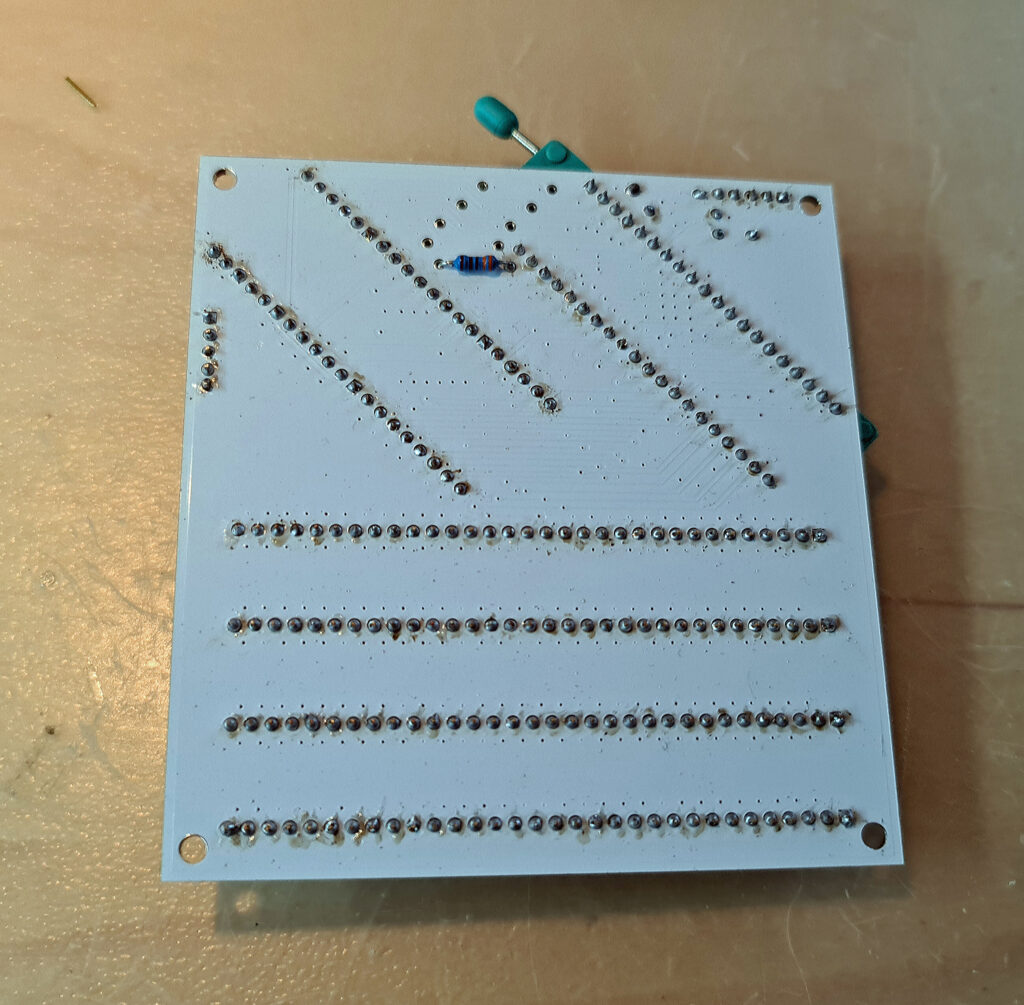
The PCBs are not designed for that, so it is a bit tight. On the Junior one resistor R1 is moved to the other side of the PCB. On the Sorbus it fits!
The RP2040 is placed in a pin bus connector, so it can be replaced.
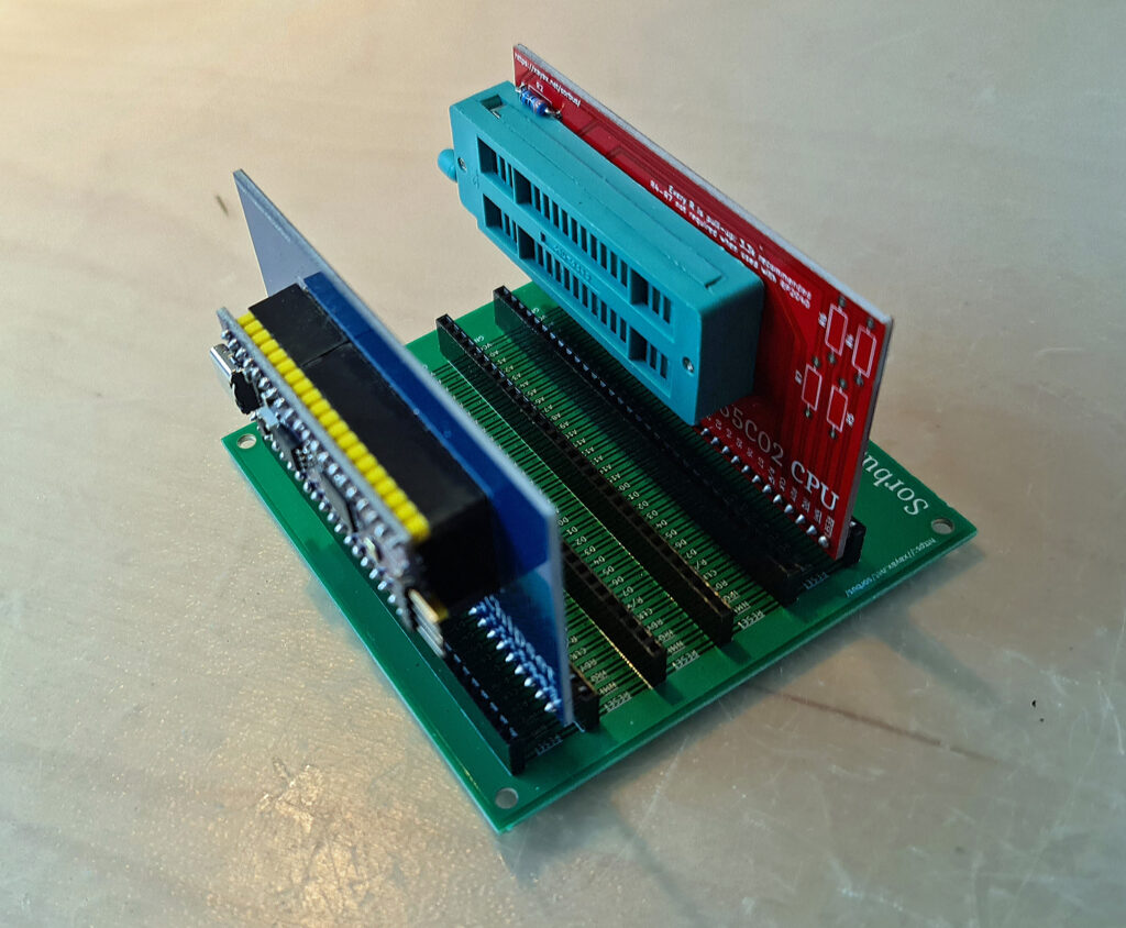
All these additions increase the height of the PCBs. But it fits.
