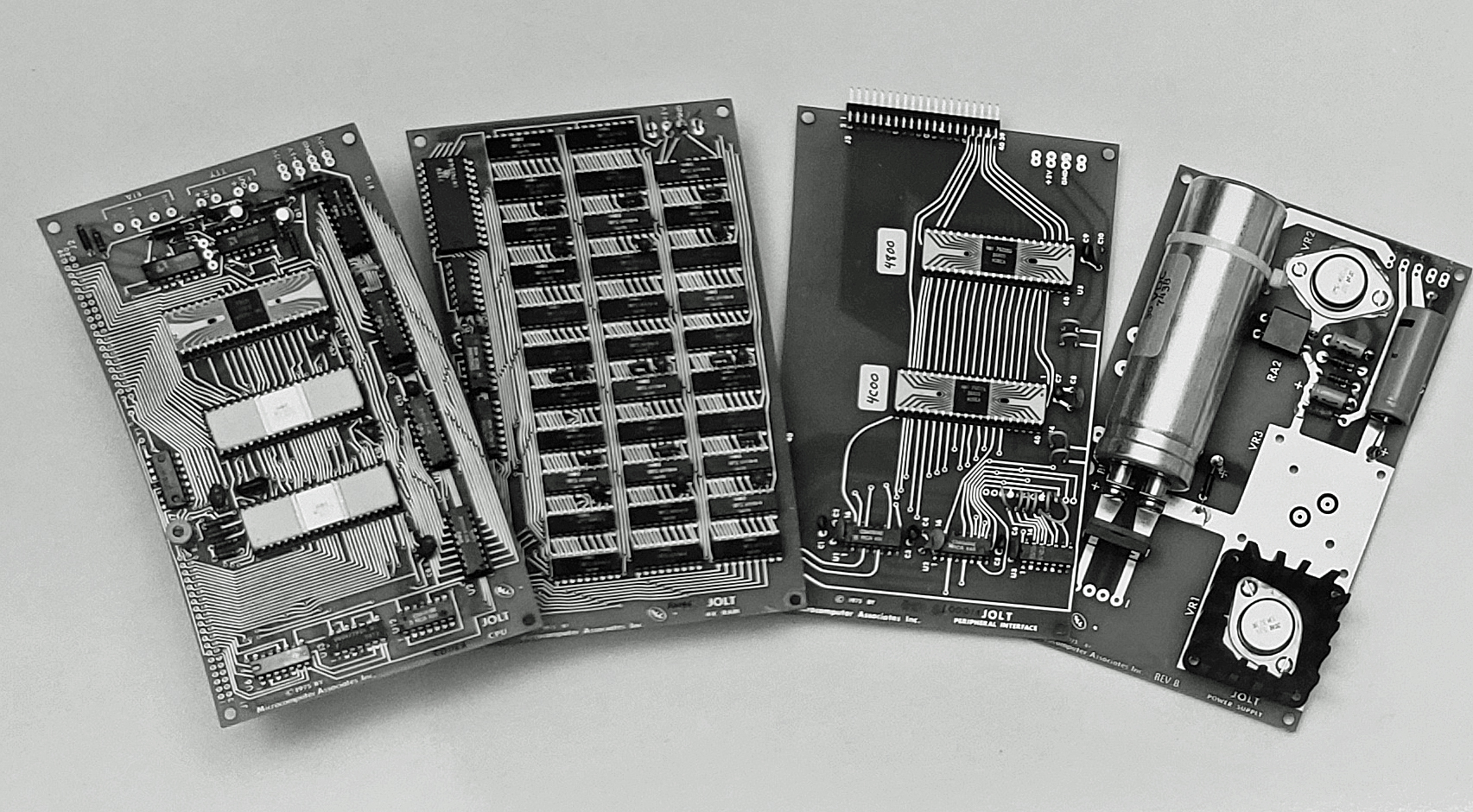
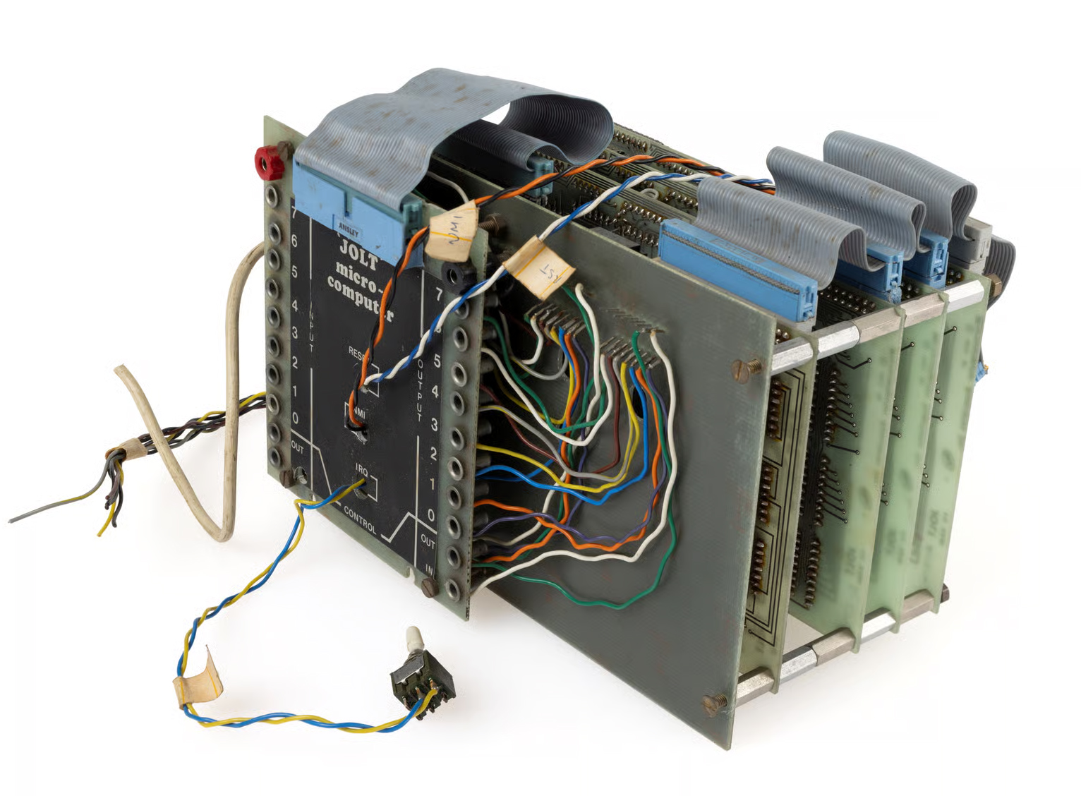
A number of cards were developed for the Jolt and he Super Jolt. This list is not complete, see the product catalogs for more cards produced.
To be placed above/under and connected with flatcable.
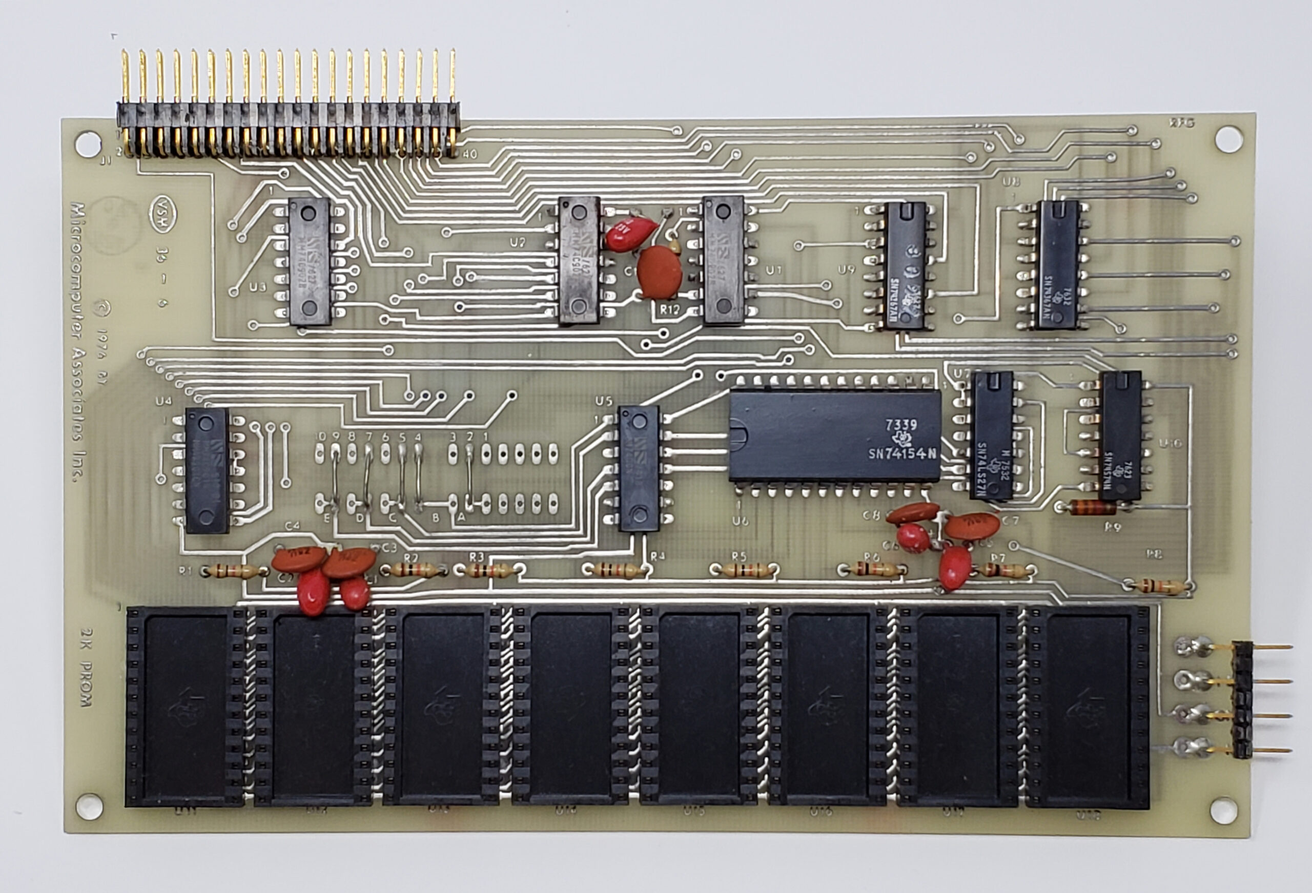
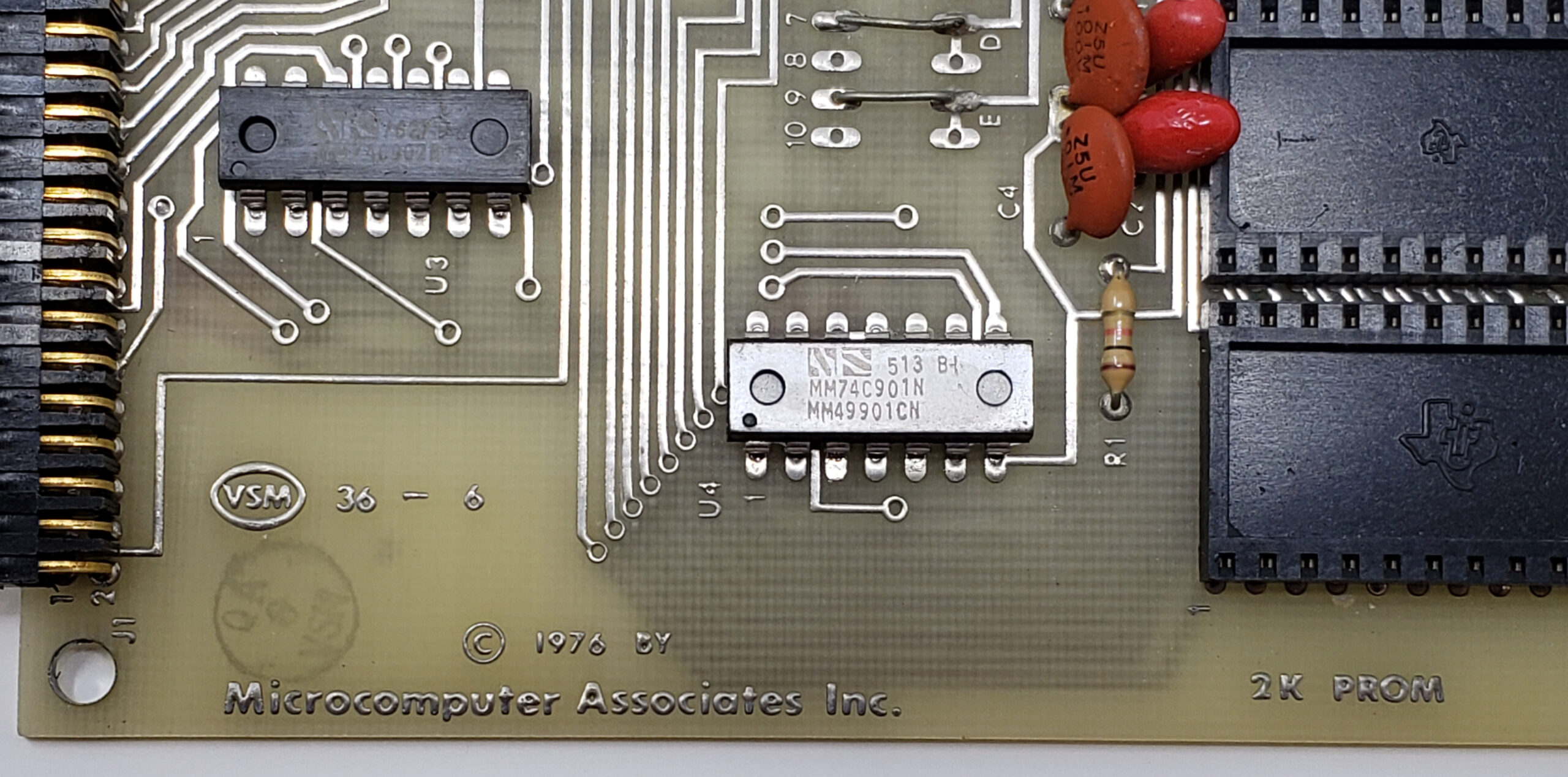
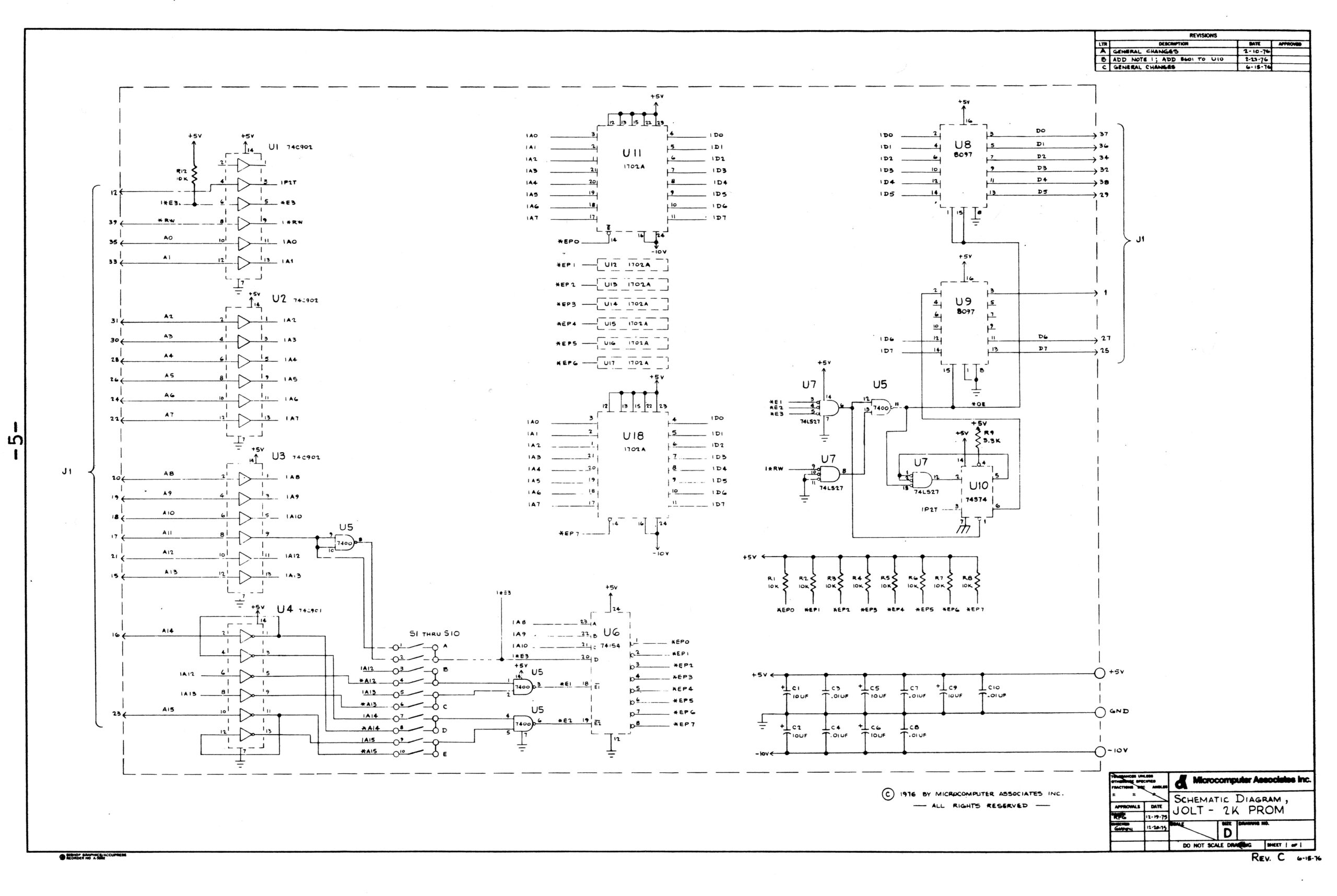
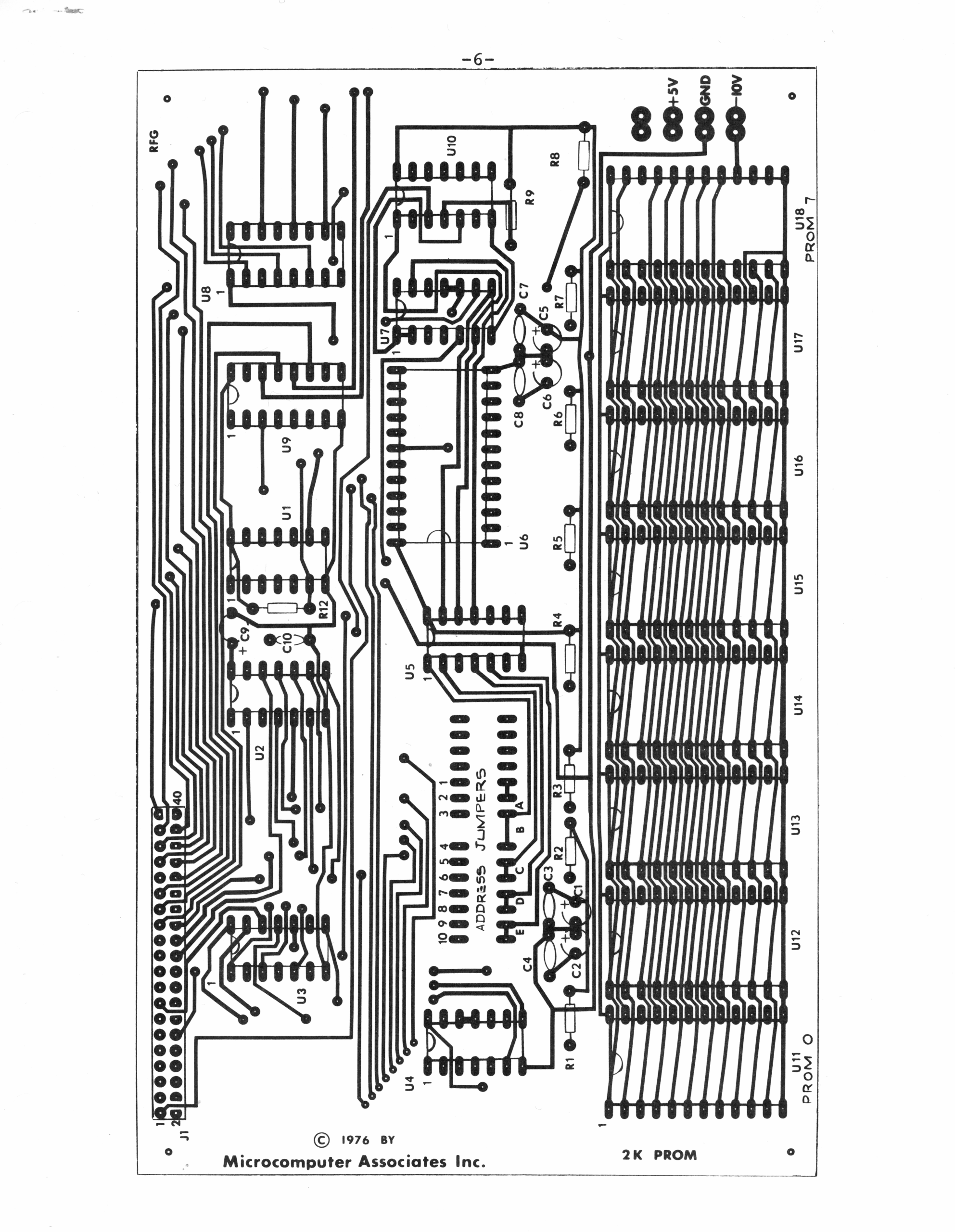
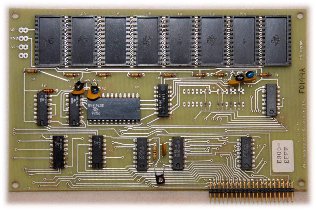
2K PROM
Up to 2K x 8 EPROMS type 1702 or 1702A
 |
2K PROM Hardware Manual |
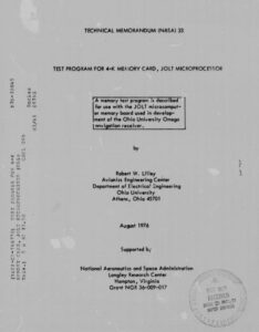 |
Test Program by NASA of the 4K RAM card |
Copyright by Florian Stassen
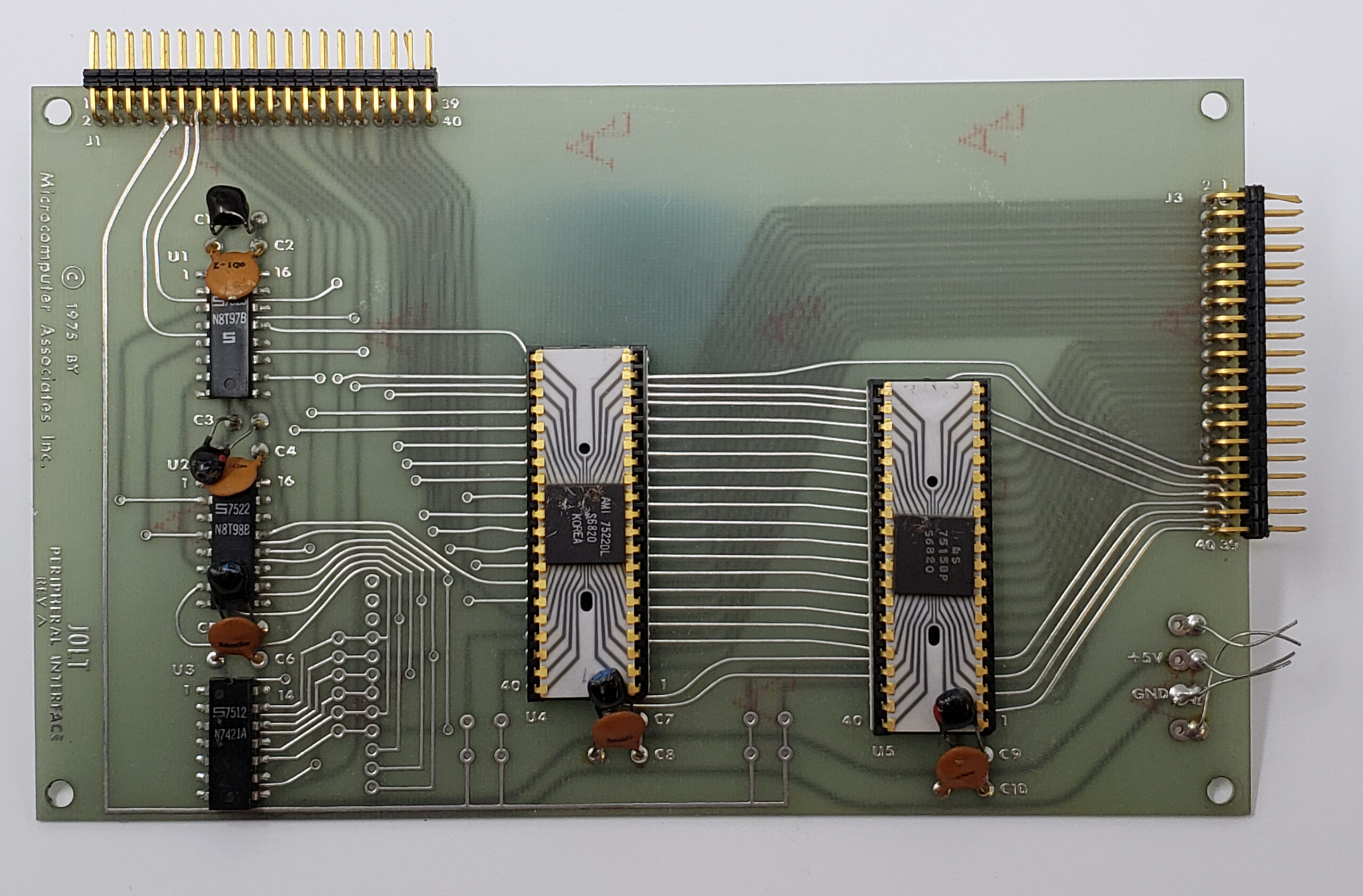
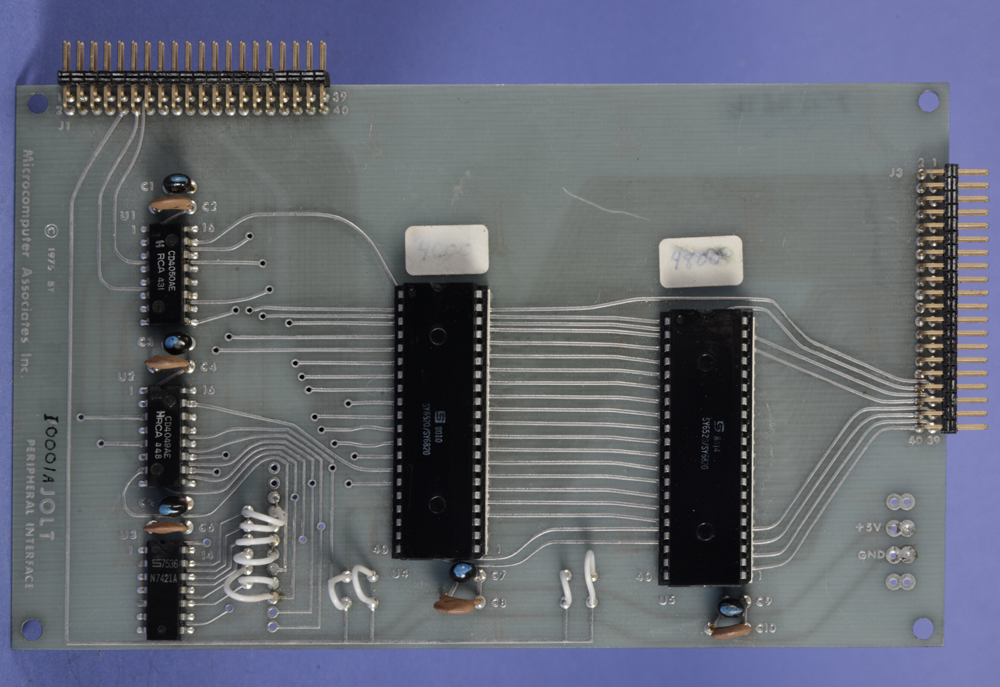
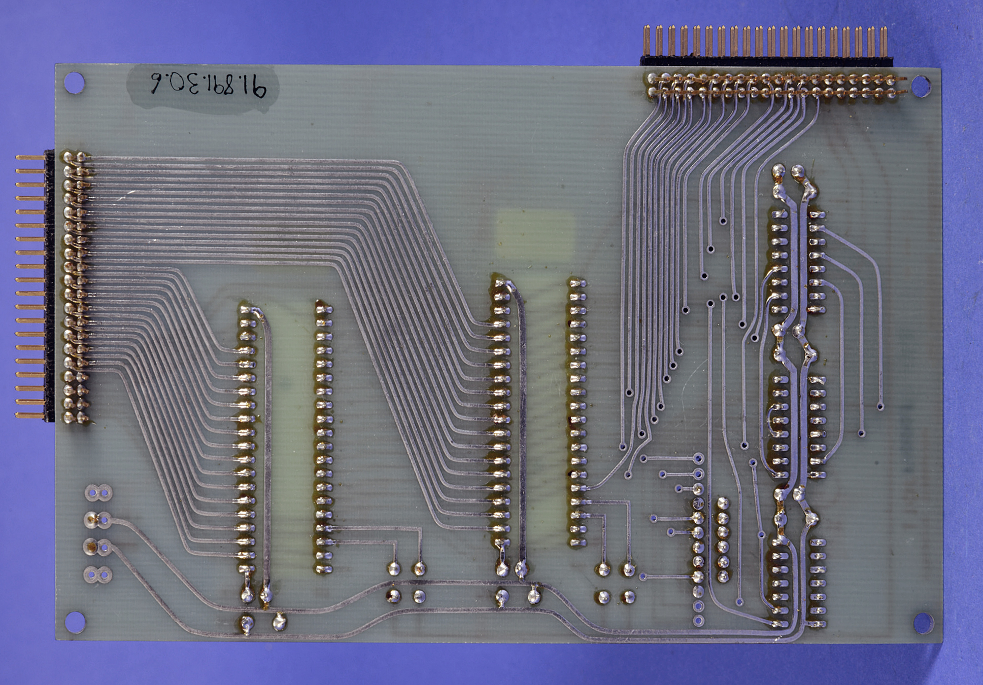
Peripheral I/O
A card with two PIAs 6820/6821.
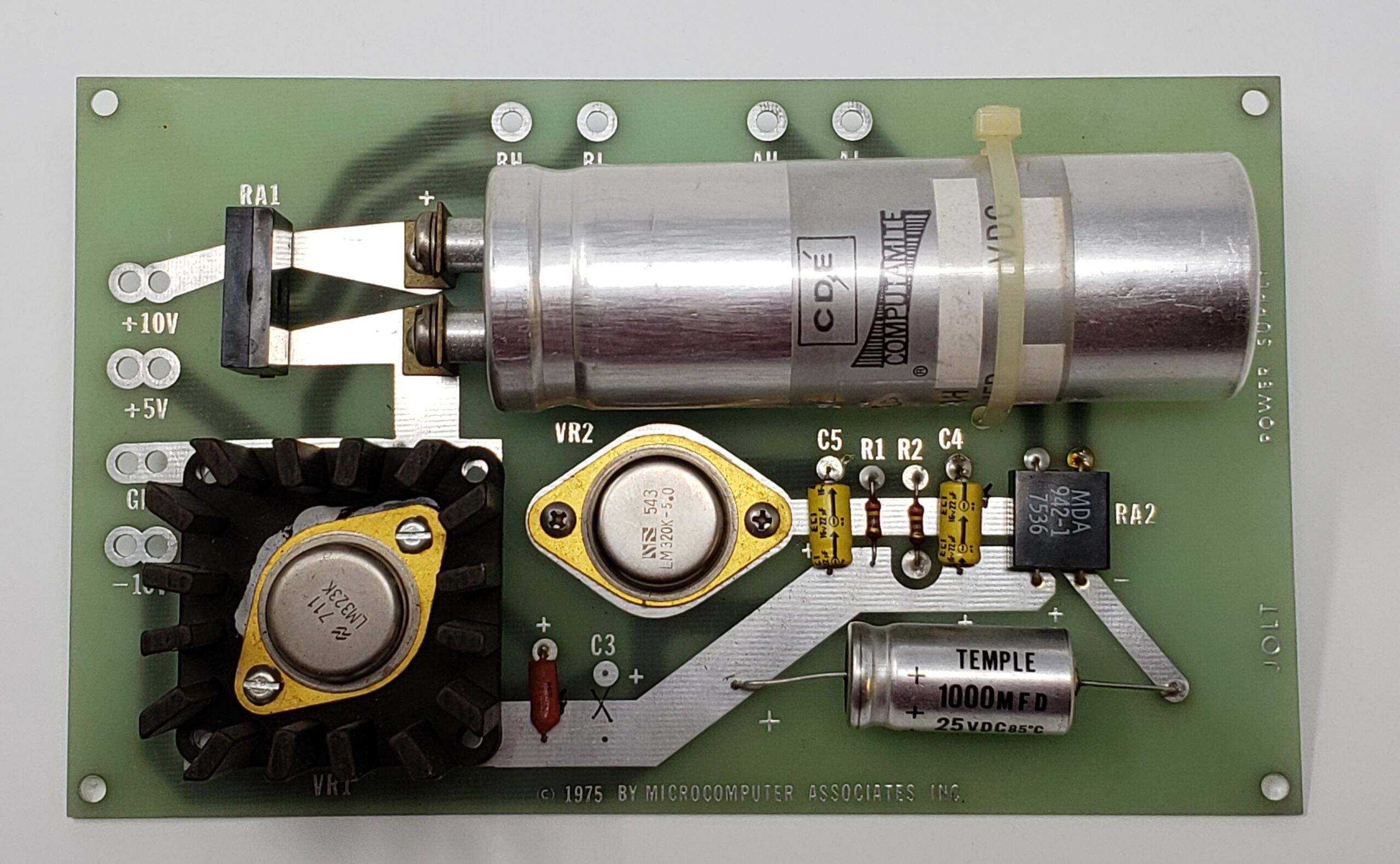
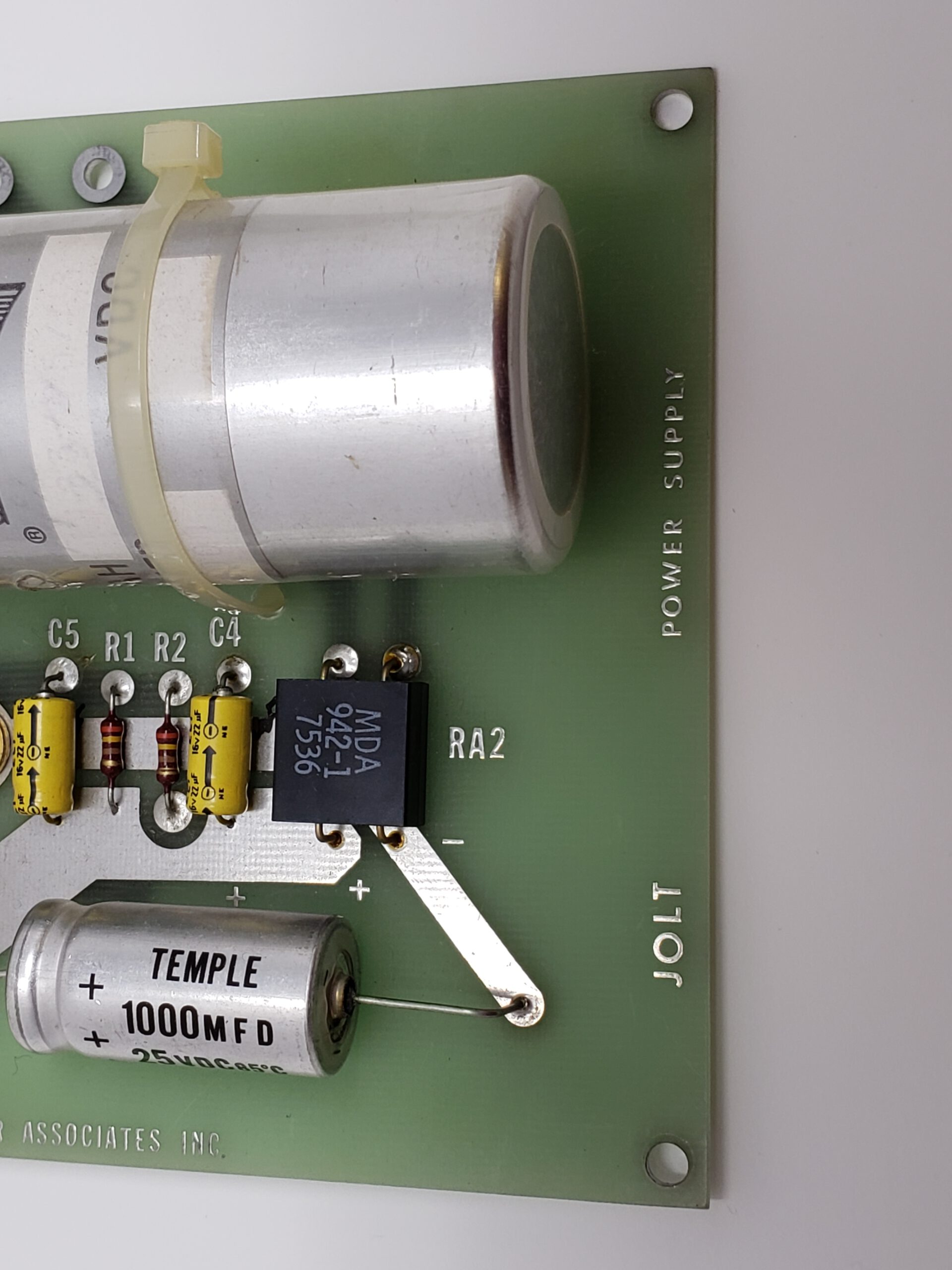
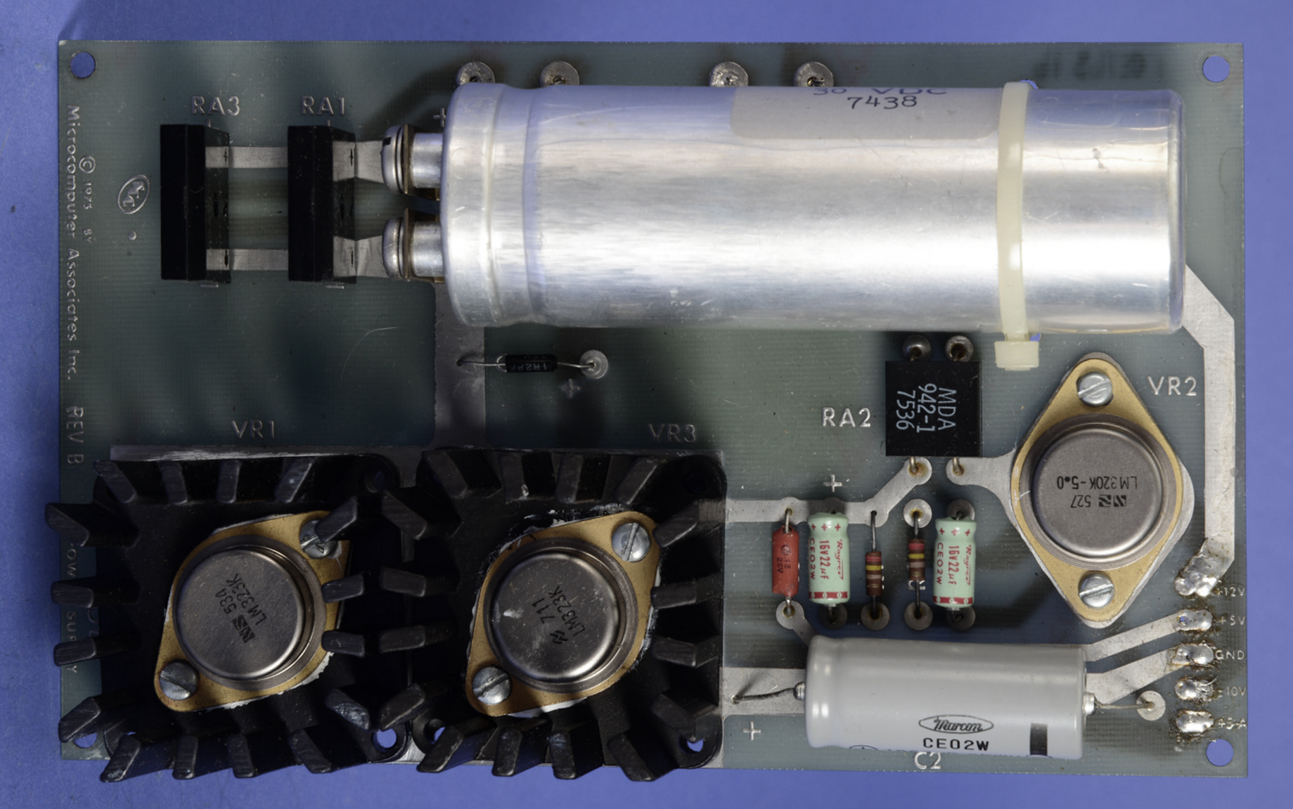
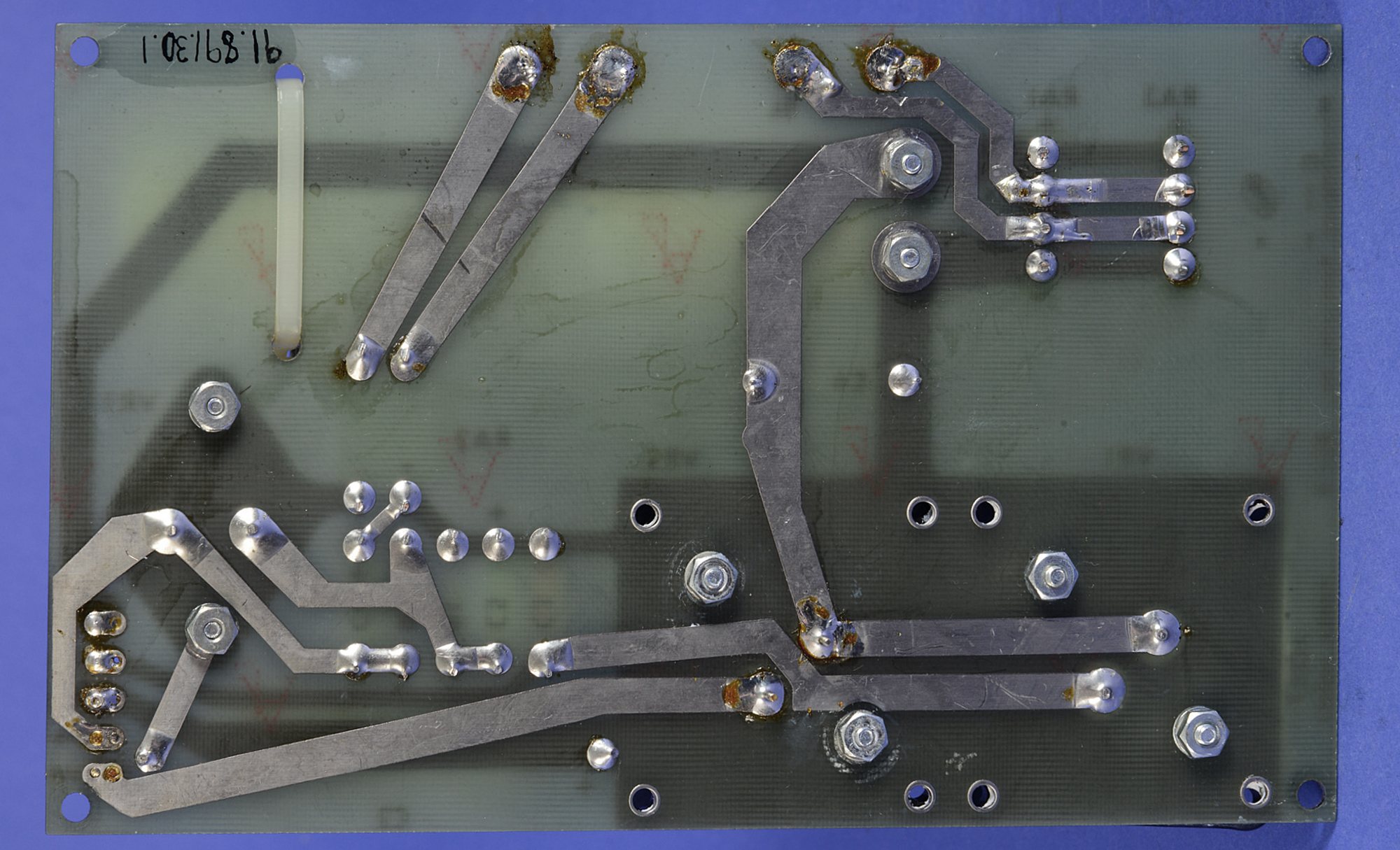
Power supply
A board with the dimensions of the Jolt delivering +12V 5V and -10V.
RAM card
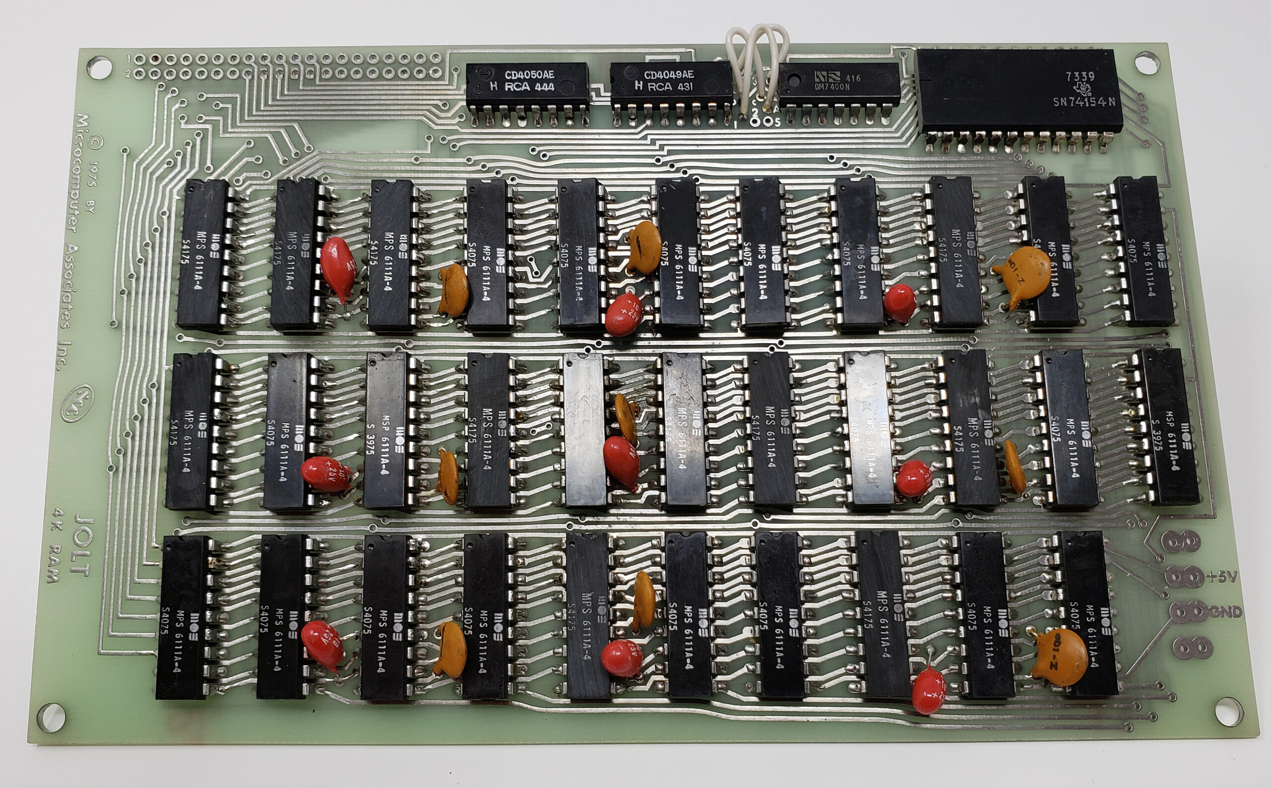
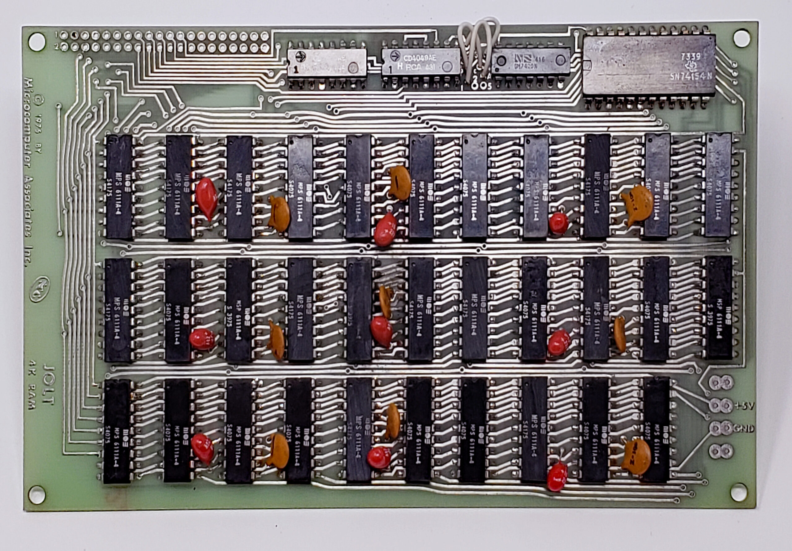
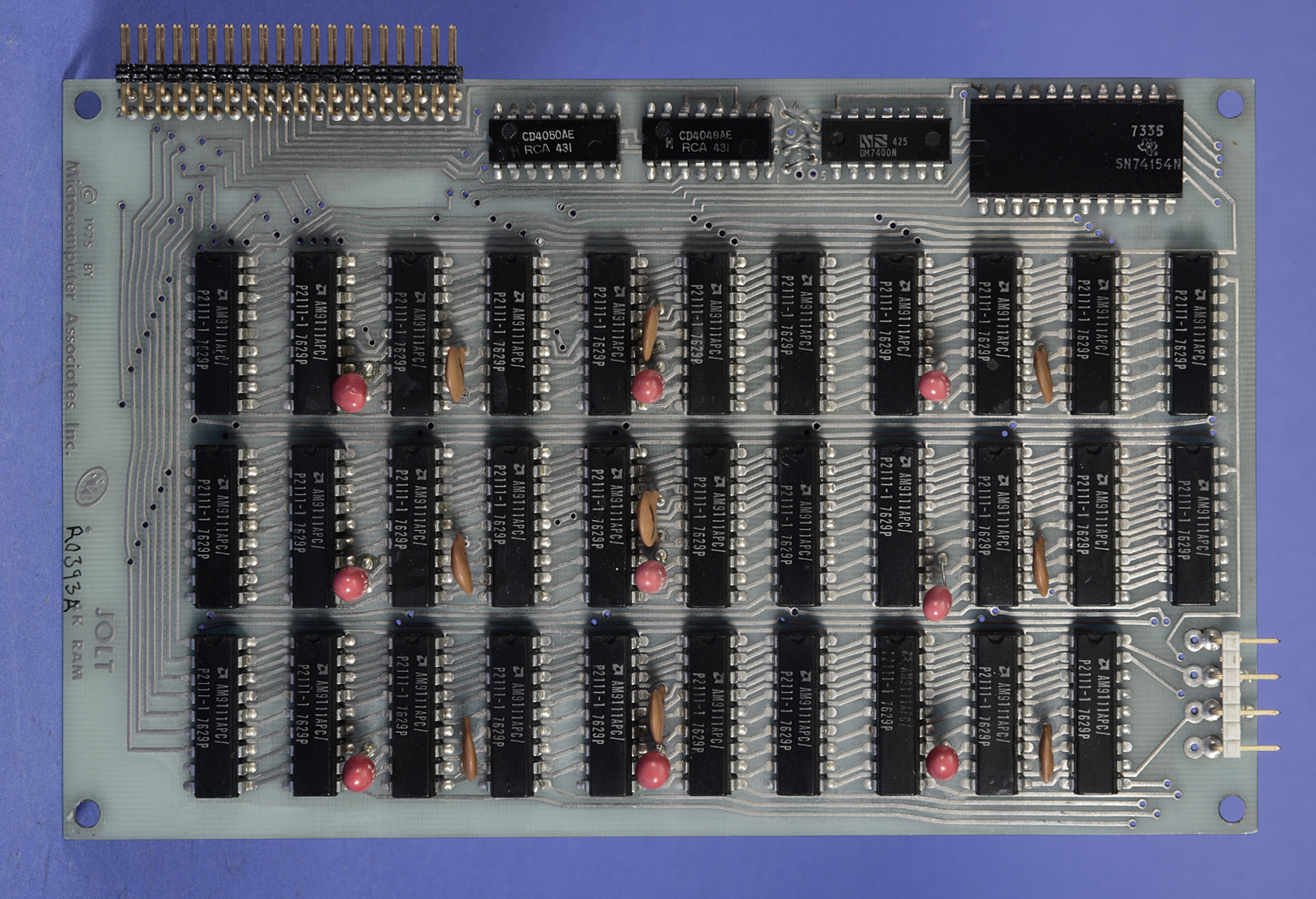
4K static RAM with 32 SRAM ICs type 2111.
Packaged onto the 4.25 x 7-inch JOLT board are a total of 36 integrated circuits, of which 32 are the memory devices. The only other components are 18 bypass-capacitors and three jumper wires. Each memory IC is organized as 256 4-bit words. Multiplying 256 by the 32 IC’s gives 8192 4-bit words. Converting to the 8-bit word length of the 6502 μP, the number of words is halved to 4096, or 4K for short.
There are 8 input-address leads to each memory IC to address the 28 (256) words, and 4 output lines. The eight least-significant address lines (AO-A8) originating from the CPU card, feed the eight memory-address terminals of all the memory IC’s in parallel. CPU address lines A8 through A11 are the inputs for a 74154 4-line to 16-line decoder. Each output from this IC connects to the enable pins on a pair of memory IC’s. The four input/output data leads on one of the pair connects to the RAM hoard data lines DO through D3, and the other circuit to D4 through D7.
This leaves the upper four address lines A12 through A15. In the JOLT scheme of things, one-half the total memory space has been reserved for user RAM and the other half for inputs, outputs and other peripheral functions such as the interval timer on the MOS Technology 6530 IC. The A14 input is permanently wired to the chip-enable pins of all the 32 memory circuits, which blocks off two 16K blocks from 400016 to 7FFF16 and C00016 to FFFF16.
Address lines A12, A13, and A15 or their complements are connected to assign the 4K hoard to a segment of the remaining 32K memory space. Two gates of a 7400 quad 2-input NAND gate are wired as a three-input gate that connects to the two enable pins of the 4-to-16 line decoder. As an example, when A12, A13 and A15 are all complemented, and since A14 is permanently complemented, the most significant hex address digit of 0 would enable the decoder and the memory will respond to addressing from 0000 to 0FFF.
The basic CPU hoard comes with 512 words of RAM assigned to 0000 to 01FF. If the 4K hoard is assigned 0000 to 0FFF, the first 512 words would overlap the CPU memory space and the memory on the CPU hoard would have to he removed. Microcomputer Associates recommends that additional memory space he filled starting at 1000. That makes good sense and that is precisely where I wired it by inserting A15 and A13, while using the noninverted A12 lead. Two CMOS circuits (a 4050 non-inverting hex-buffer and a 4049 inverting hex-buffer) buffer these high-order address lines as well as A8 through A11.
Don’t get worried by all this: the documentation is excellent and there is a simple chart telling where to connect the three jumpers for all possible memory space allocations.
Also interconnecting the CPU and RAM hoards are the eight D0 through D7 data leads and the RW (read-write) and WRITE signals. The data lines are bi-directional for both reading and writing data. RW is wired to the 32 output-disable pins in parallel. When the signal is at a logical 1 – a read condition – the data lines become high-impedance inputs. The R/W memory IC pins connect to the CPU WRITE lead: when it is low the memory is in its write state. Only the pair of memory IC’s selected to write at any time will present a low drive impedance to the data lines.
Construction of this board calls for the same care as all computer hoards. The right tools are a must and should include a first-class soldering iron and a magnifying glass. The 4K memory board can he stacked with the CPU, PIA, power supply, and future options using connectors for the address, data, and control lines, or with simple wire loops.
Typical current drain is 1-amp from a single 5-volt power supply. And typical hoards do exist since our sample took just about 1 amp. The maximum current drain is 1.9 amps. You must evaluate your power-supply situation and may have to beef up its capacity. The standard JOLT supply will support a CPU, 4K RAM, and an I/O card.