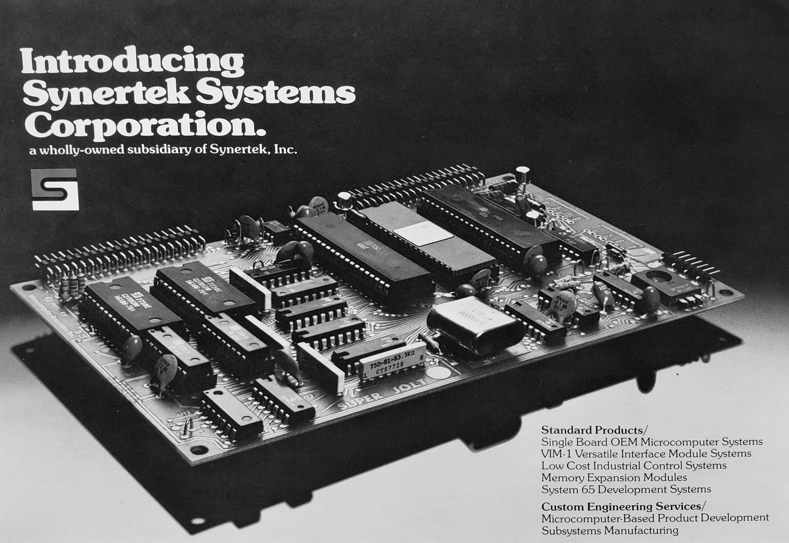
Synertek, Inc. was an American semiconductor manufacturer founded in 1973. The initial founding group consisted of Bob Schreiner (from Fairchild), Dan Floyd, Zvi Grinfas, Jack Balletto, and Gunnar Wetlesen. The manufacturing technology was MOS/LSI.
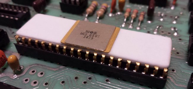
Initial products included custom designed devices, as well as a line of standard products (static RAMs, ROMs, dynamic and static shift registers) and then, sometime before 1979, second sourced versions of MOS Technology’s successful 6502 8-bit microprocessor, and the (less successful) Philips/Signetics 2650 processor and Zilog Z8 microcomputer.
Major customers included Atari (for its video game product line their biggest customer at a certain point of time) and Apple Computer (for its Apple II computer).
In the days leading up to the 1977 West Coast Computer Faire, Steve Wozniak chose to use a Synertek ROM chip for the Apple II, which was revealed at the event, after a chip from American Megatrends didn’t arrive on time.
Here some pages with information on Synertek, Micro Associates and my SYM-1 systems.
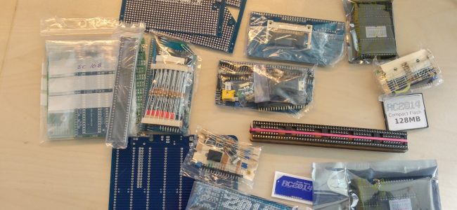
- My Synertek collection photos
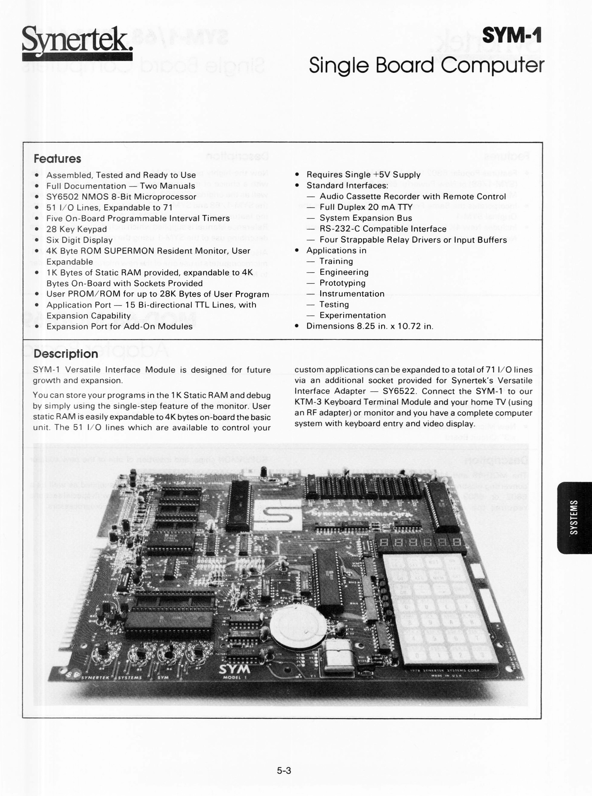
- SYM-1
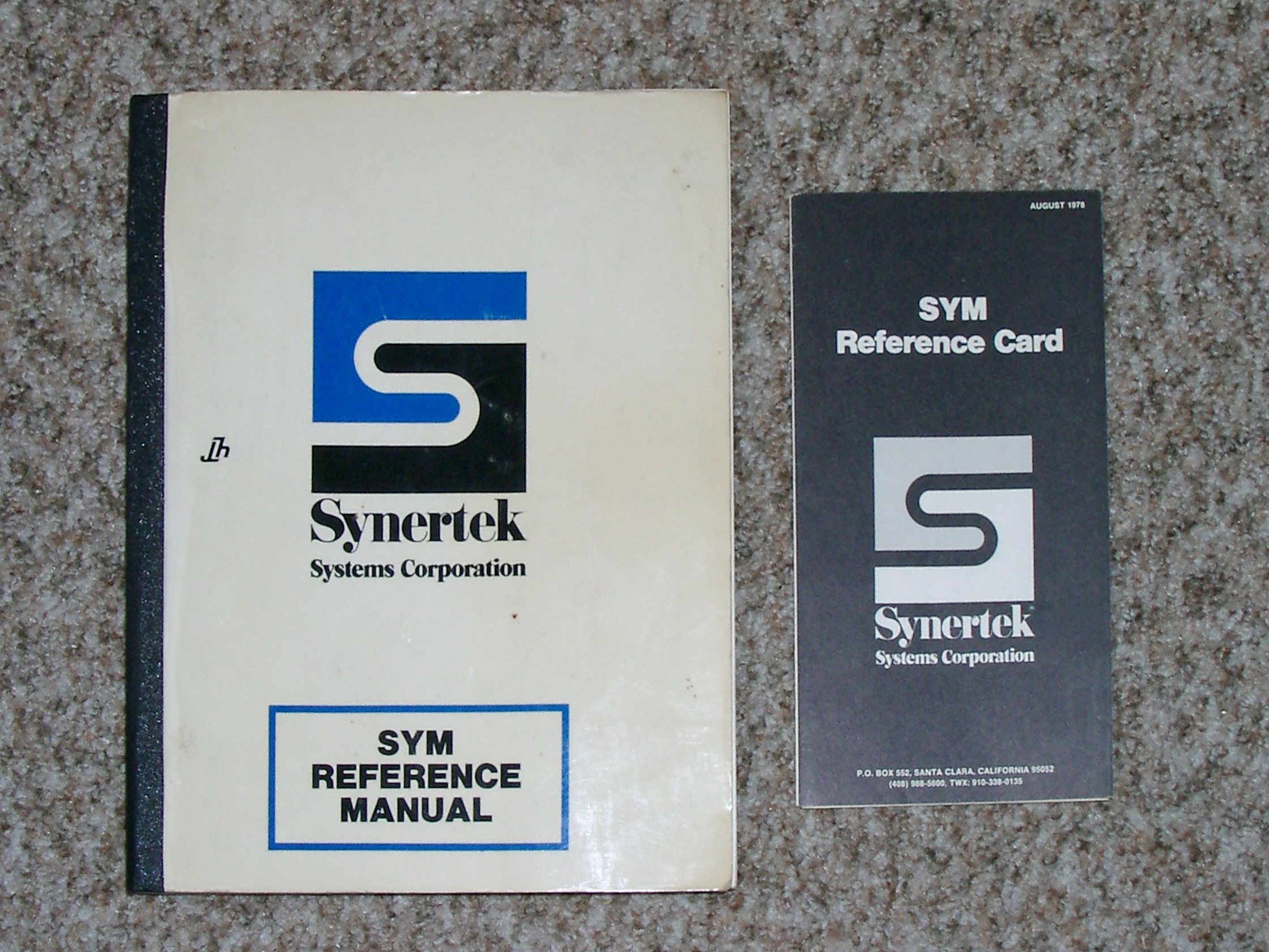
- SYM-1 Manuals and Ref cards
- SYM-1 Monitor
- SYM-1 Pascal and Forth
- 2532 to 2732 EPROM adapter
- SYM-Physis The SYM-1 Users’ Group newsletter
- SYM-1 Basic
- Symtool
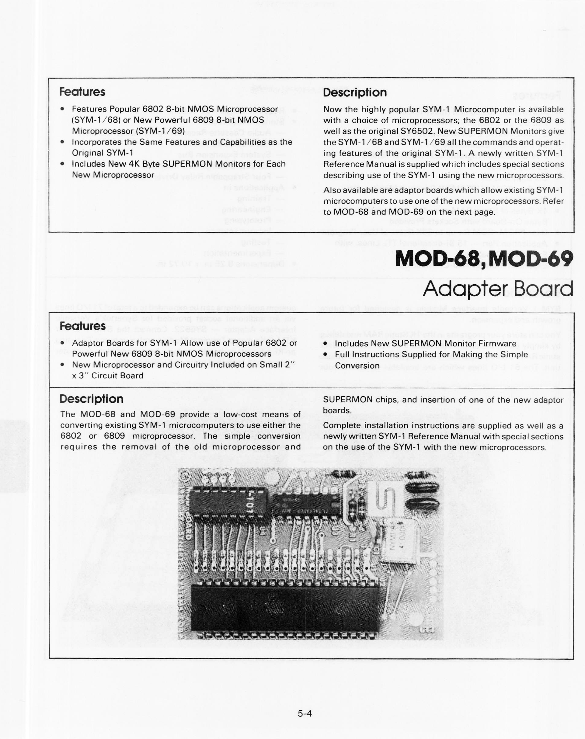
- SYM-1 MOD-68 MOD-69
- SYM-1 1541 DOS
- SYM-1 6502 mini and Maxi SBC
- PicoSYM, a SYM-1 emulator on a Raspberry Pico
- SYMulator a SYM-1 emulator
- C, Basic, RAE on the SYM-1
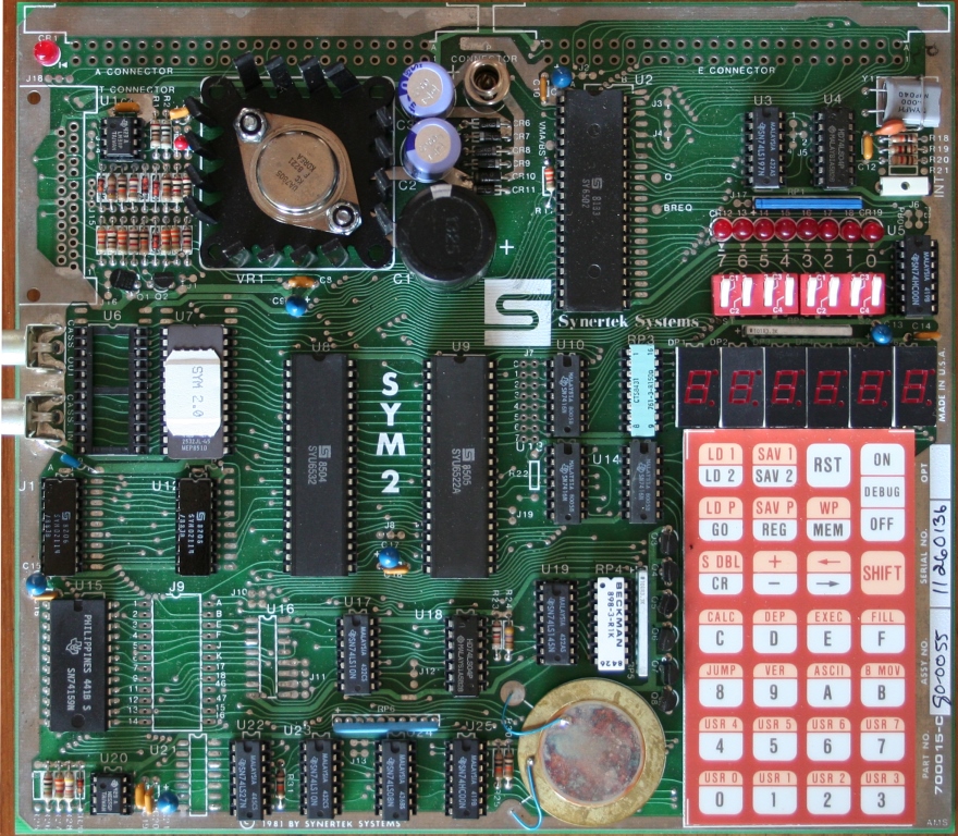
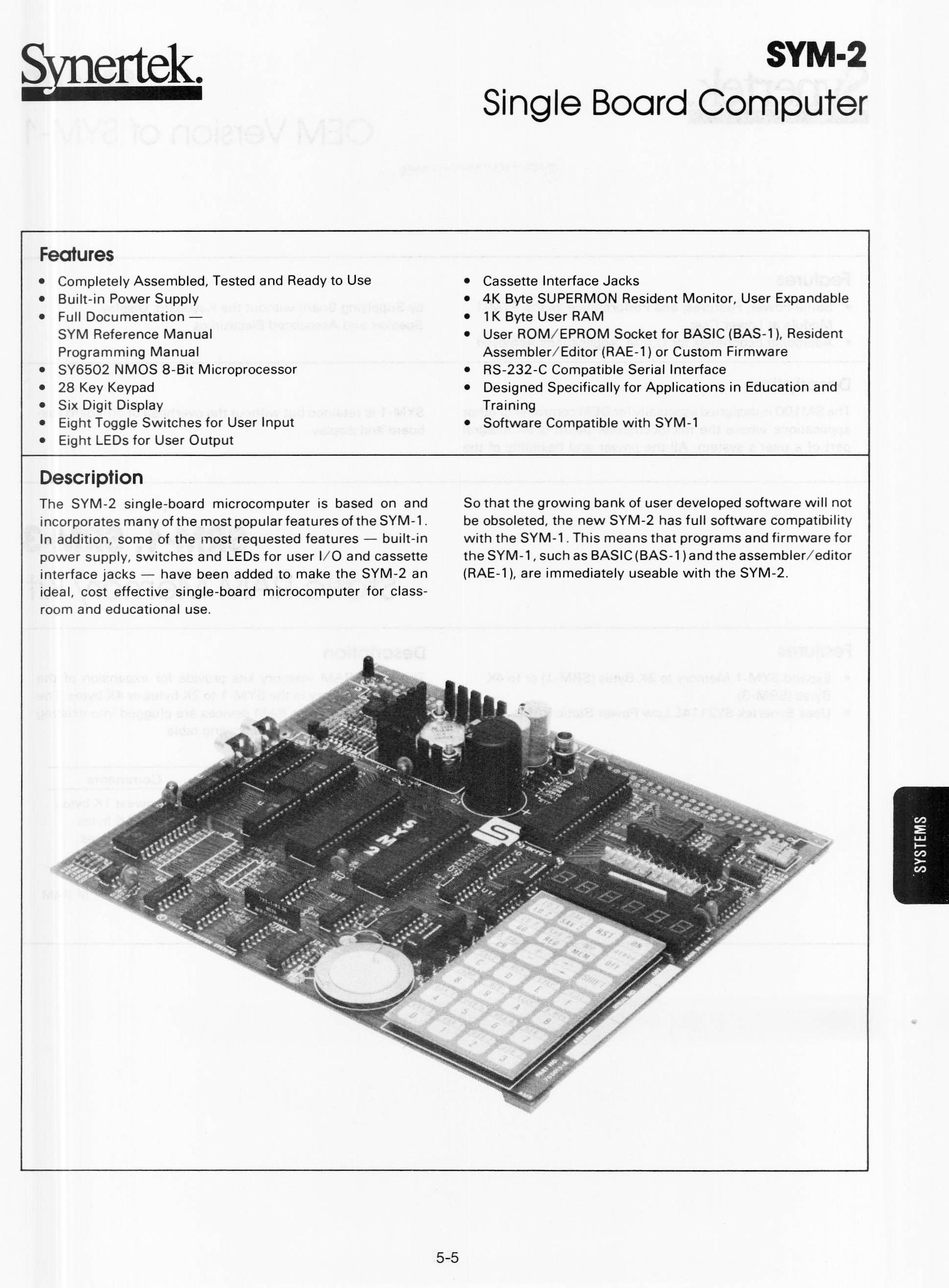
- SYM-2
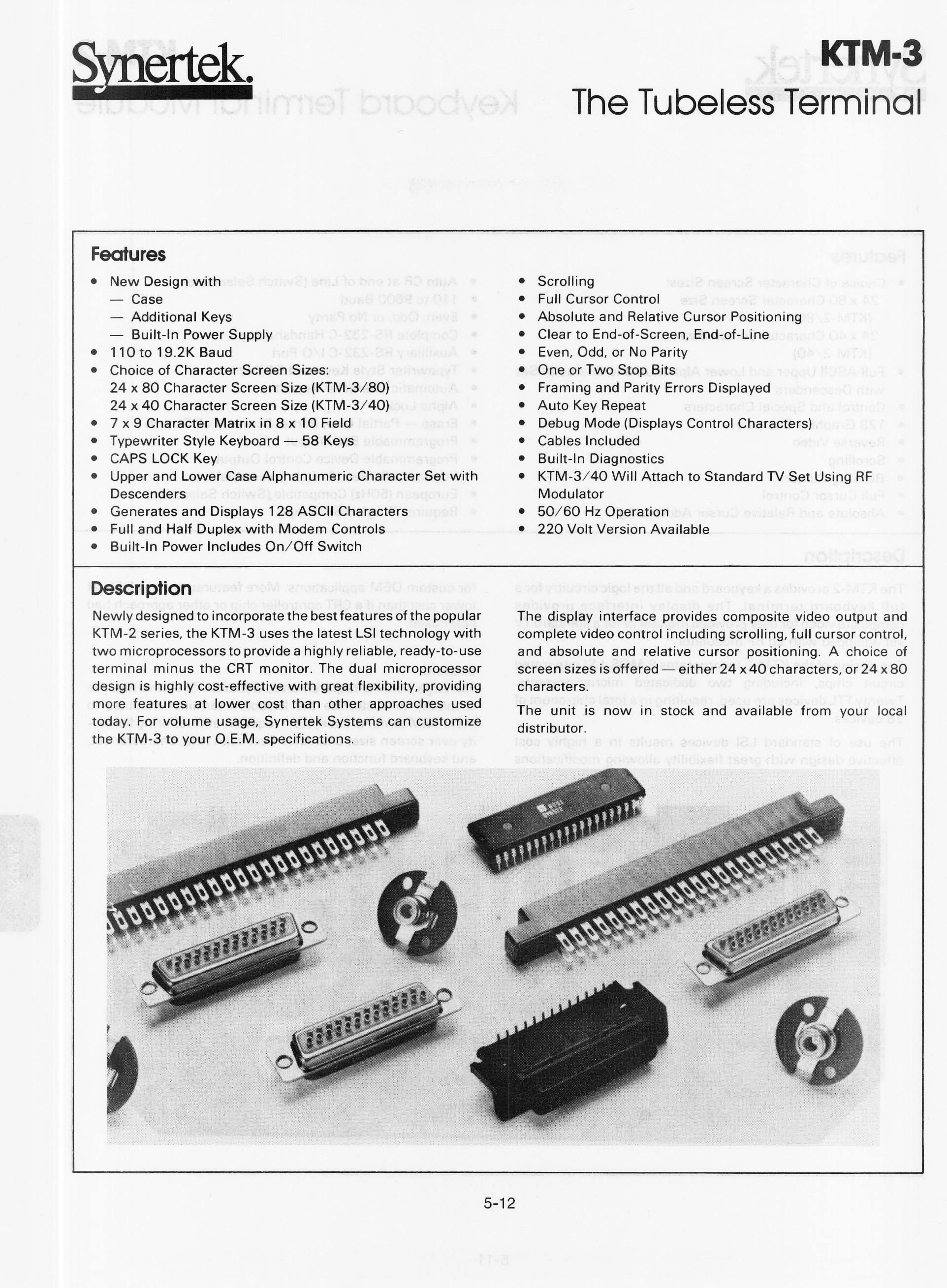
- KTM-3
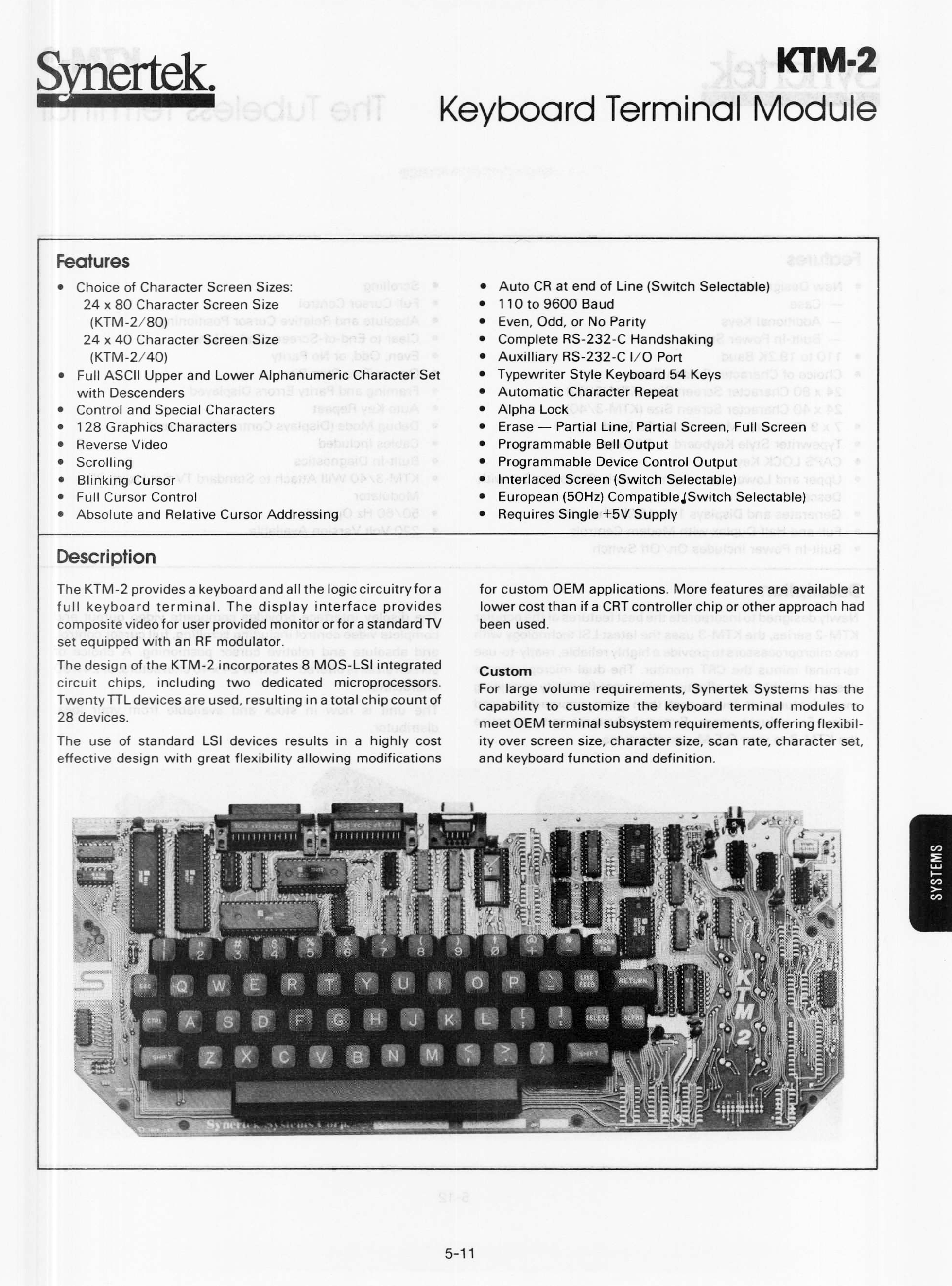
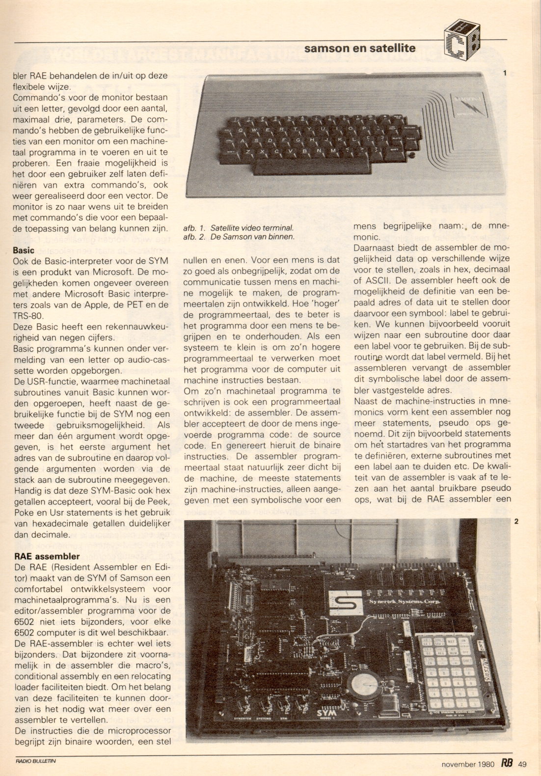
- KTM-2 & KTM_2/80
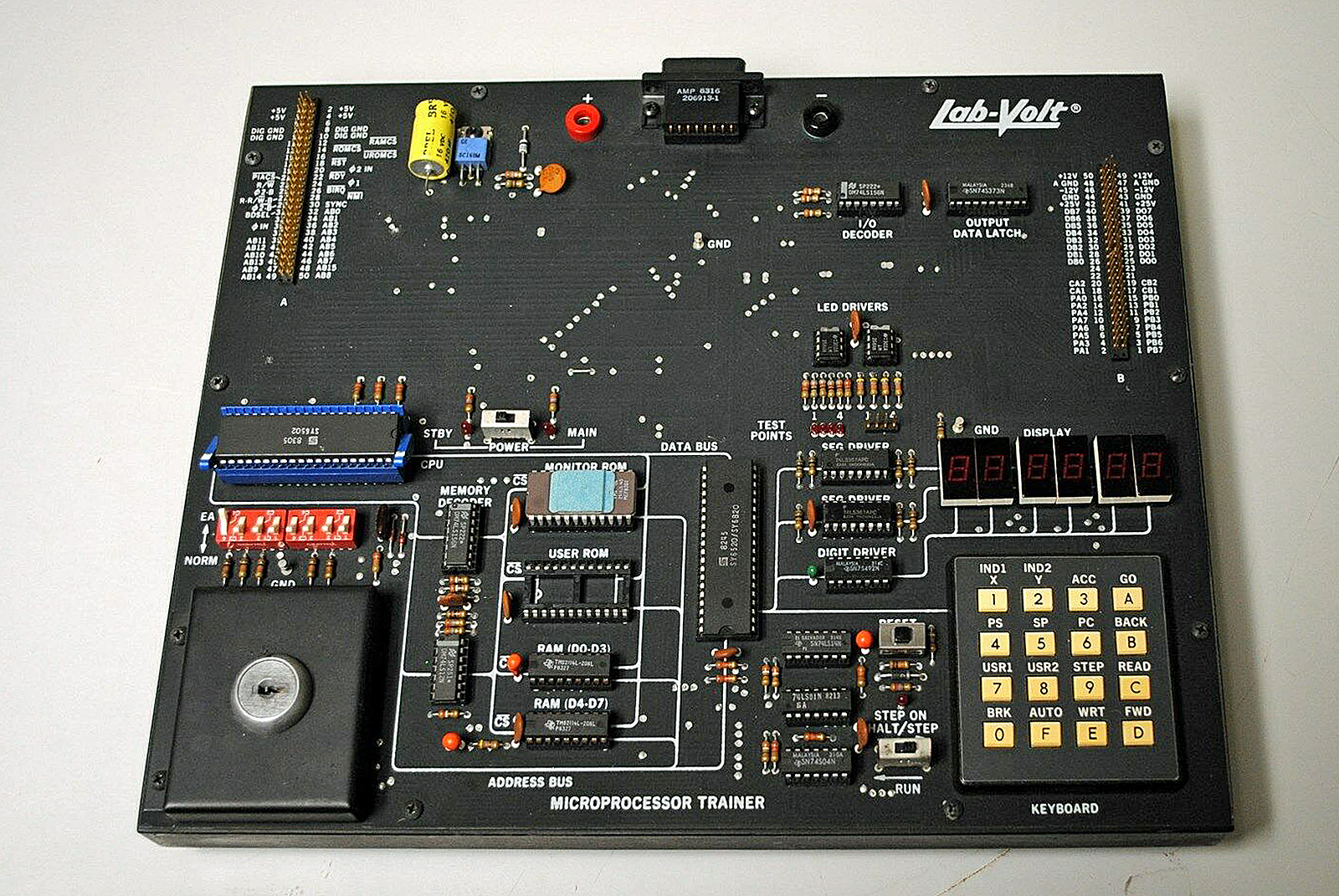
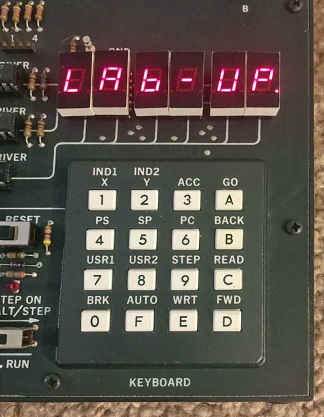
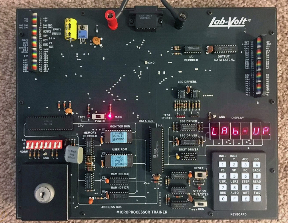
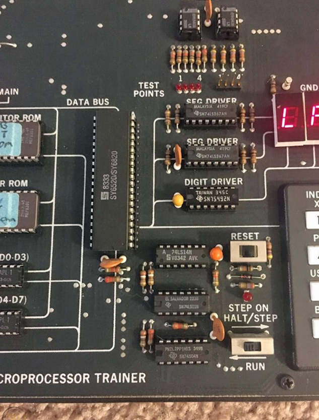
- Synertek MDT 1000
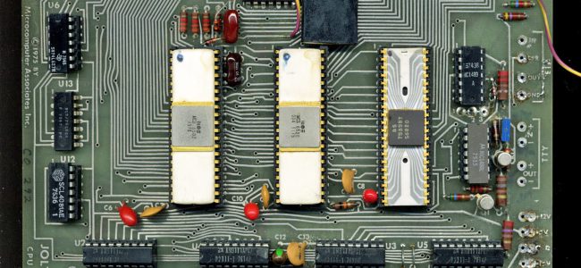
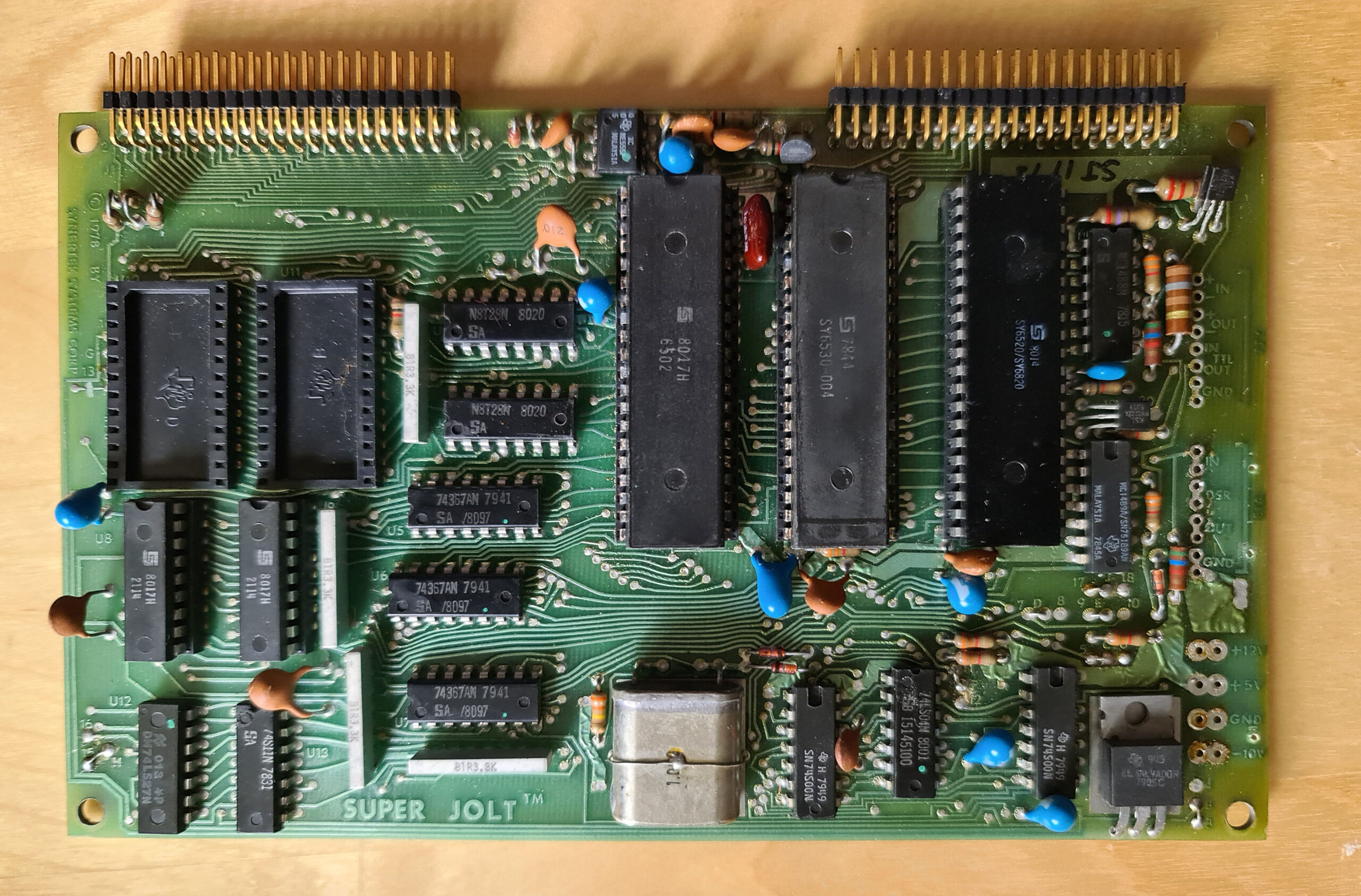
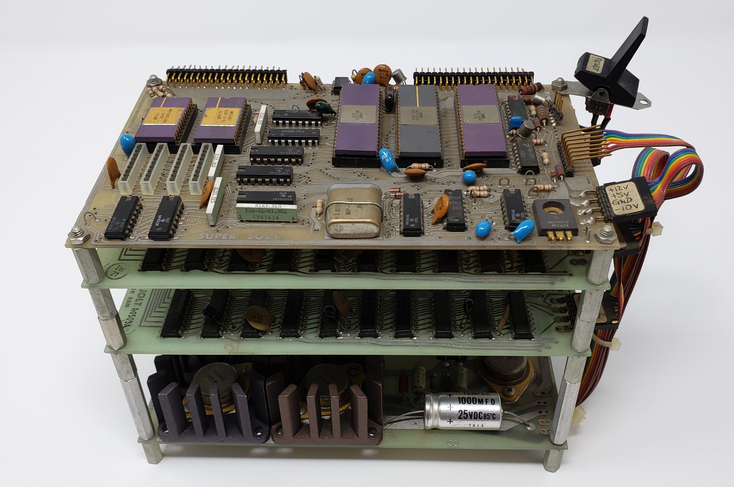
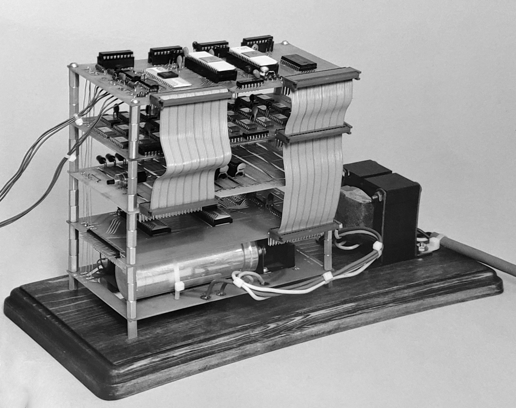
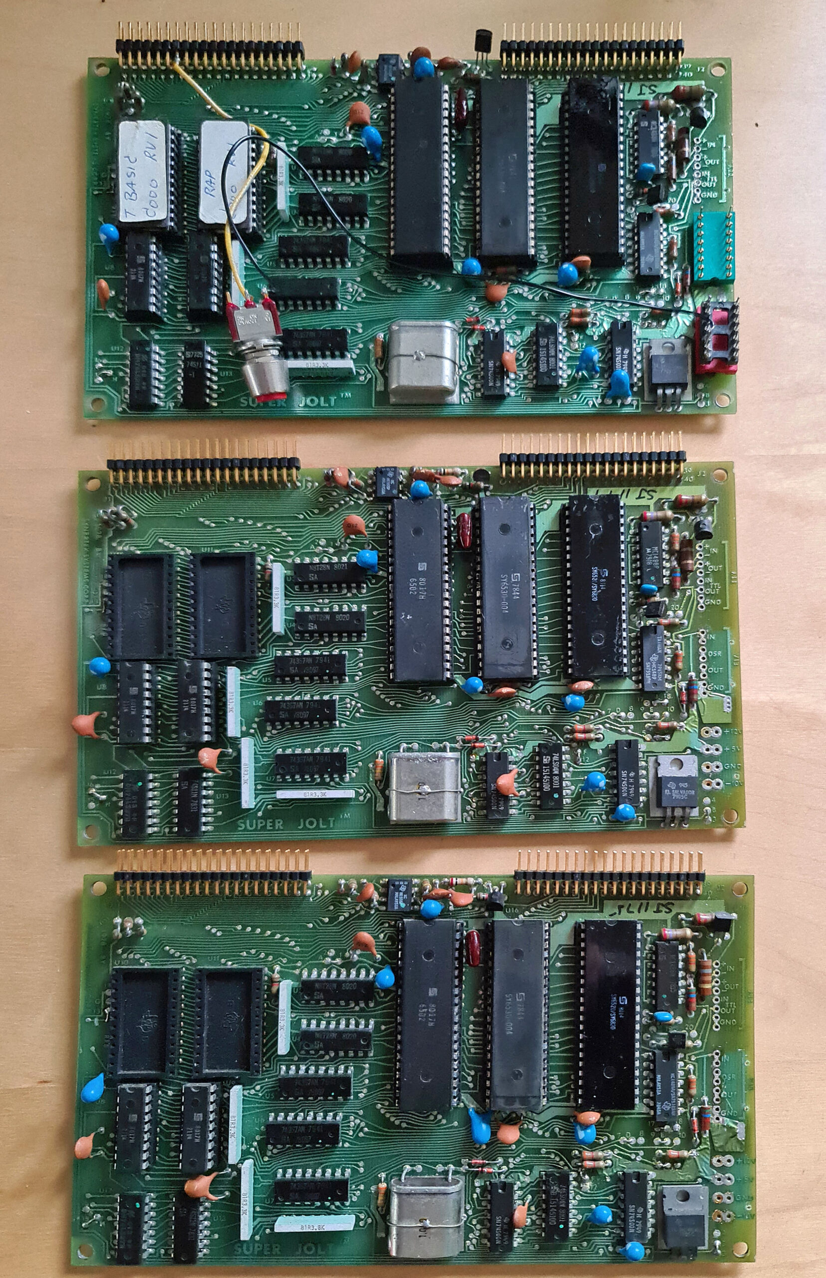
The Jolt from Micro Associates and initialy not a Synertek product, has its own page here.
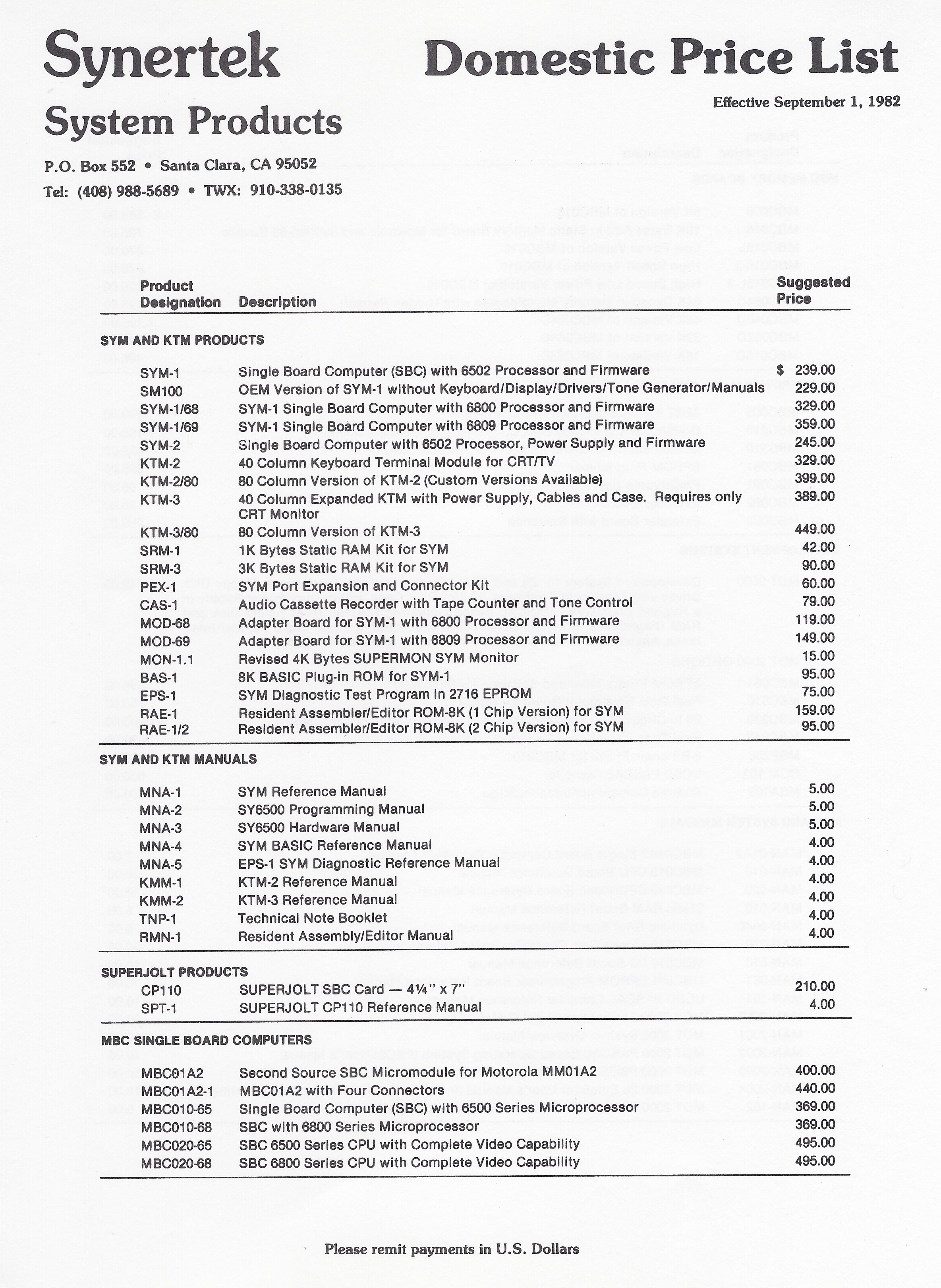
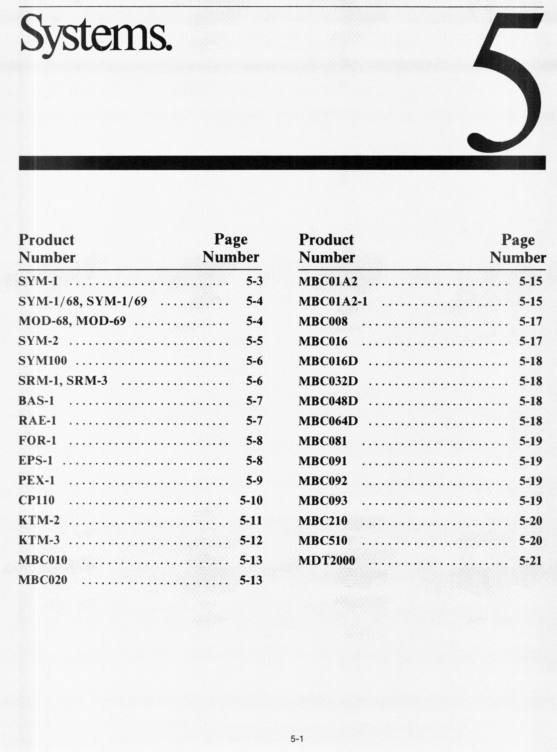
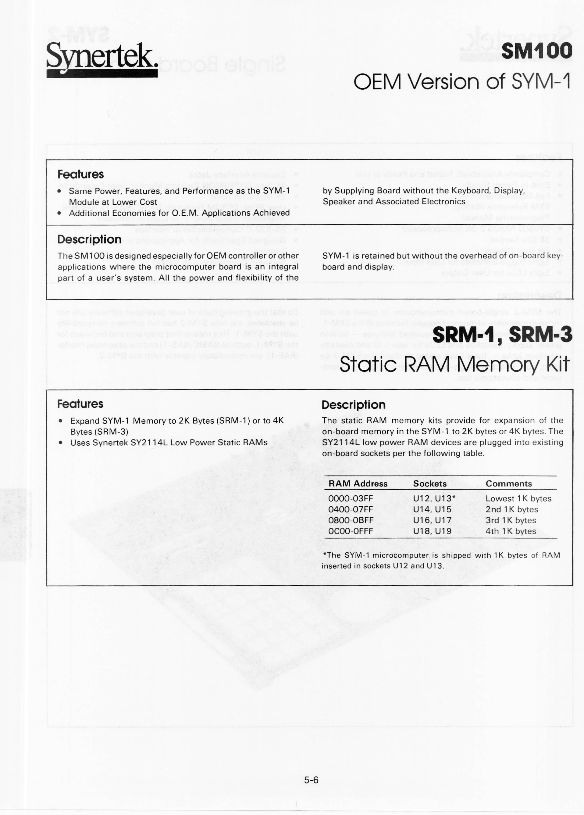
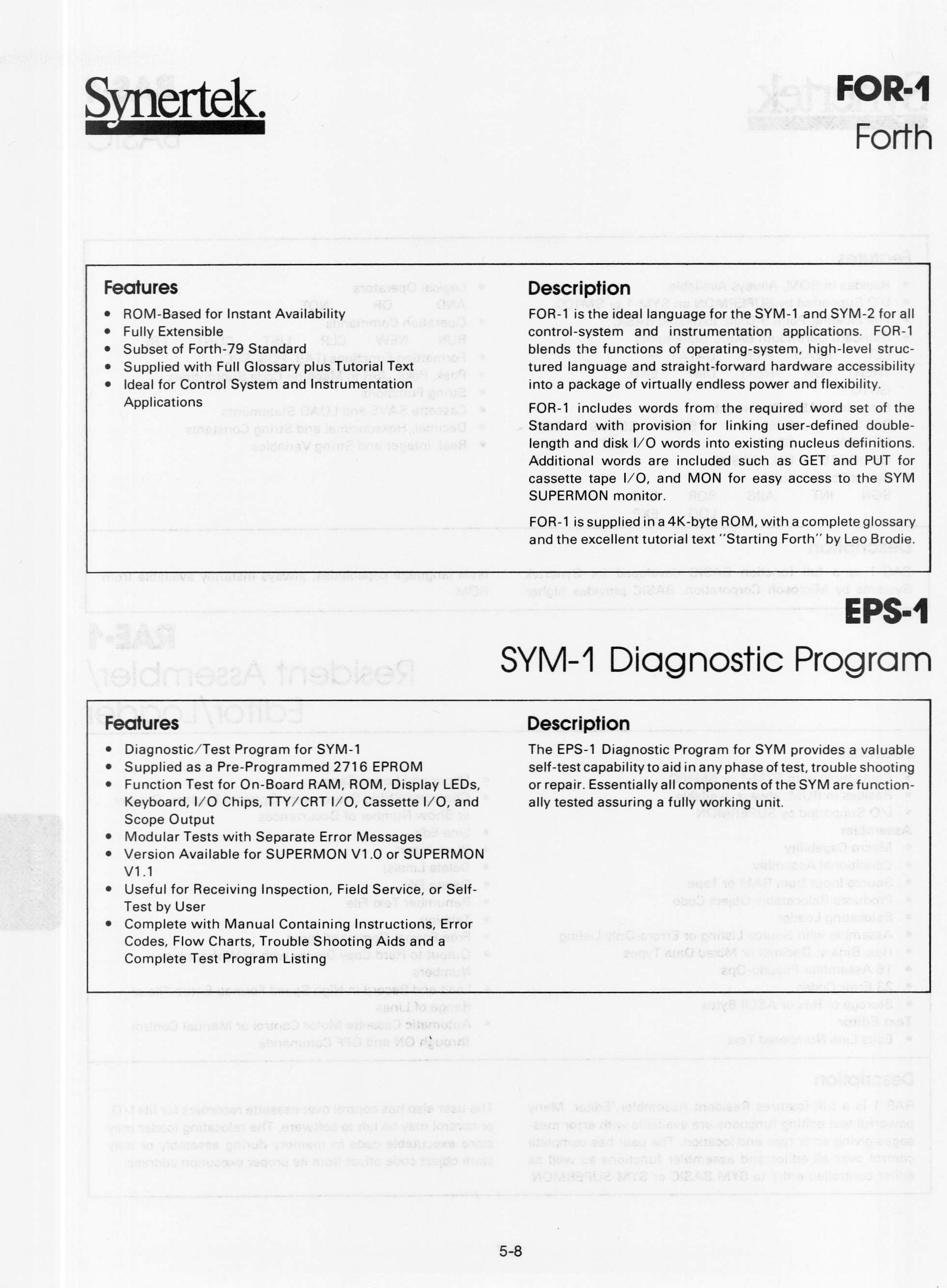
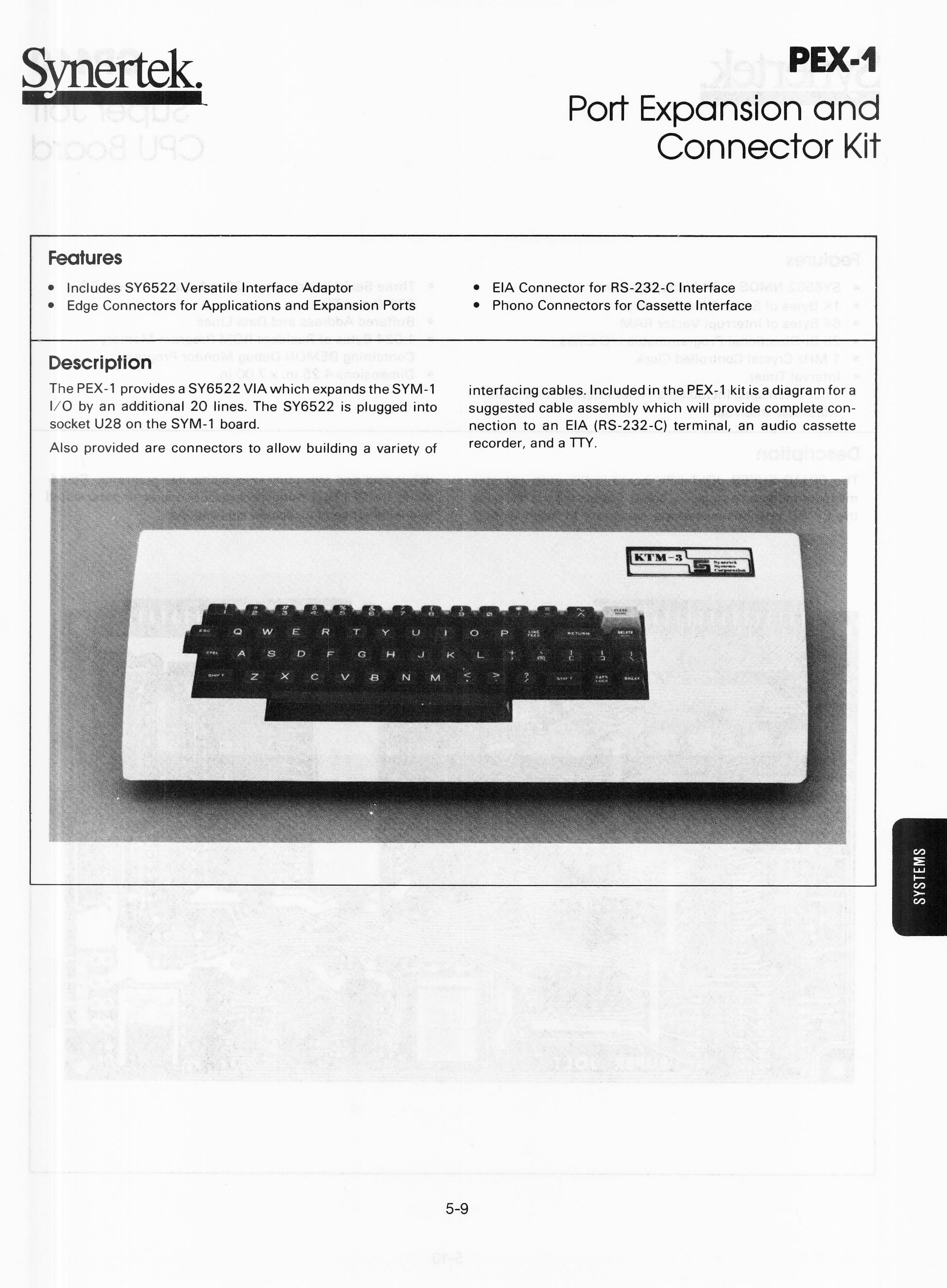
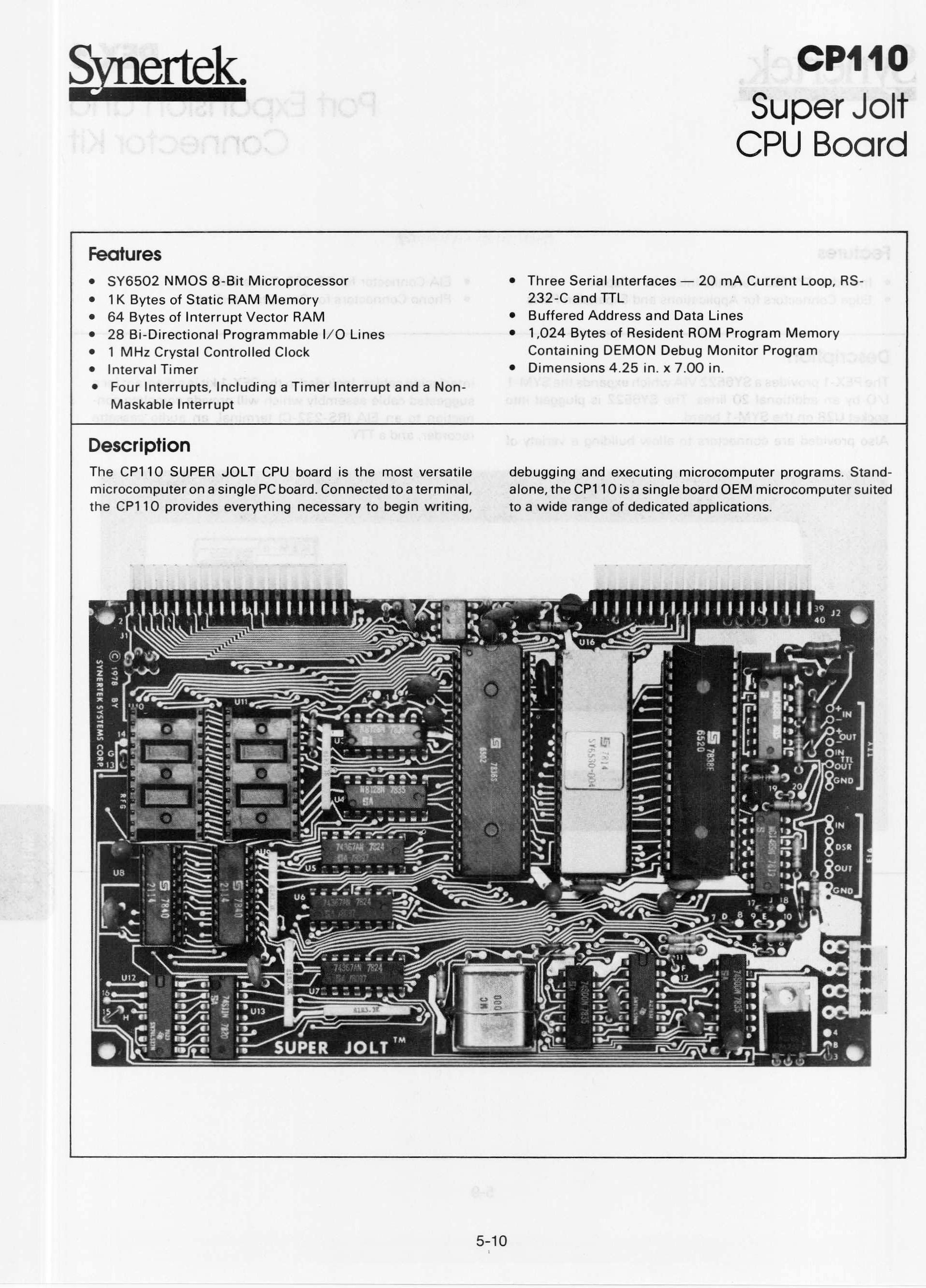
Synertek Databook 1983 Chapter 5 Systems![]()
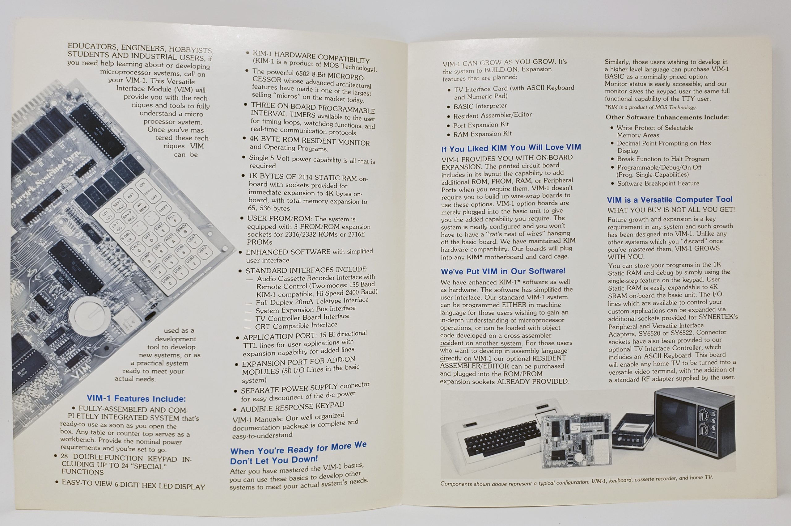
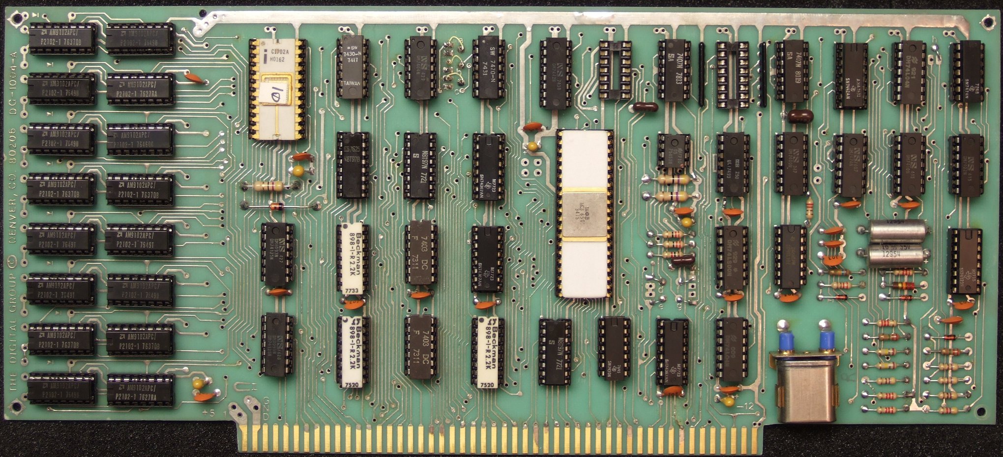
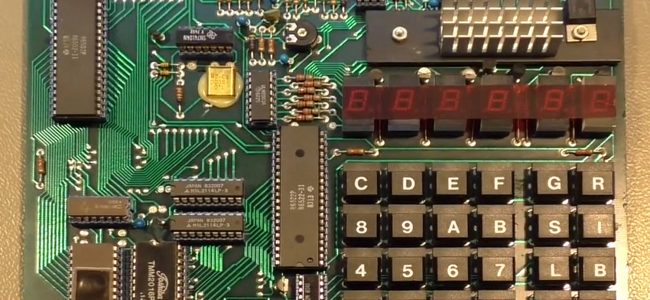
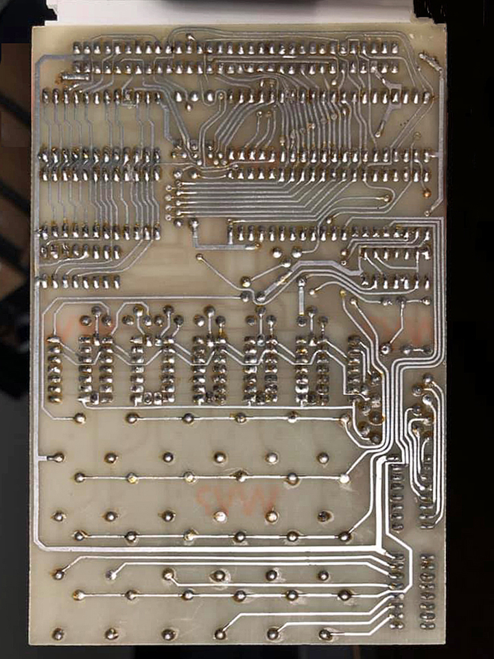
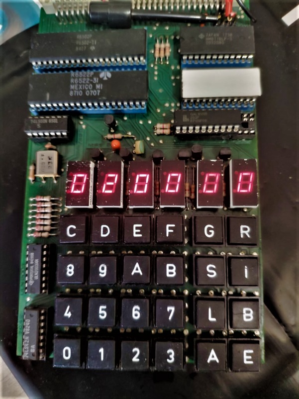
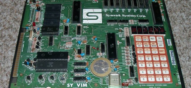
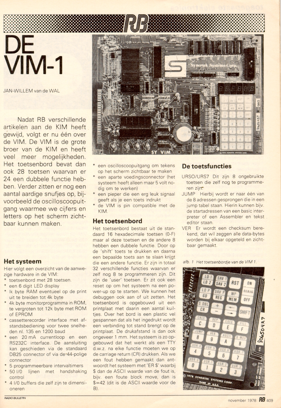
My VIM-1:

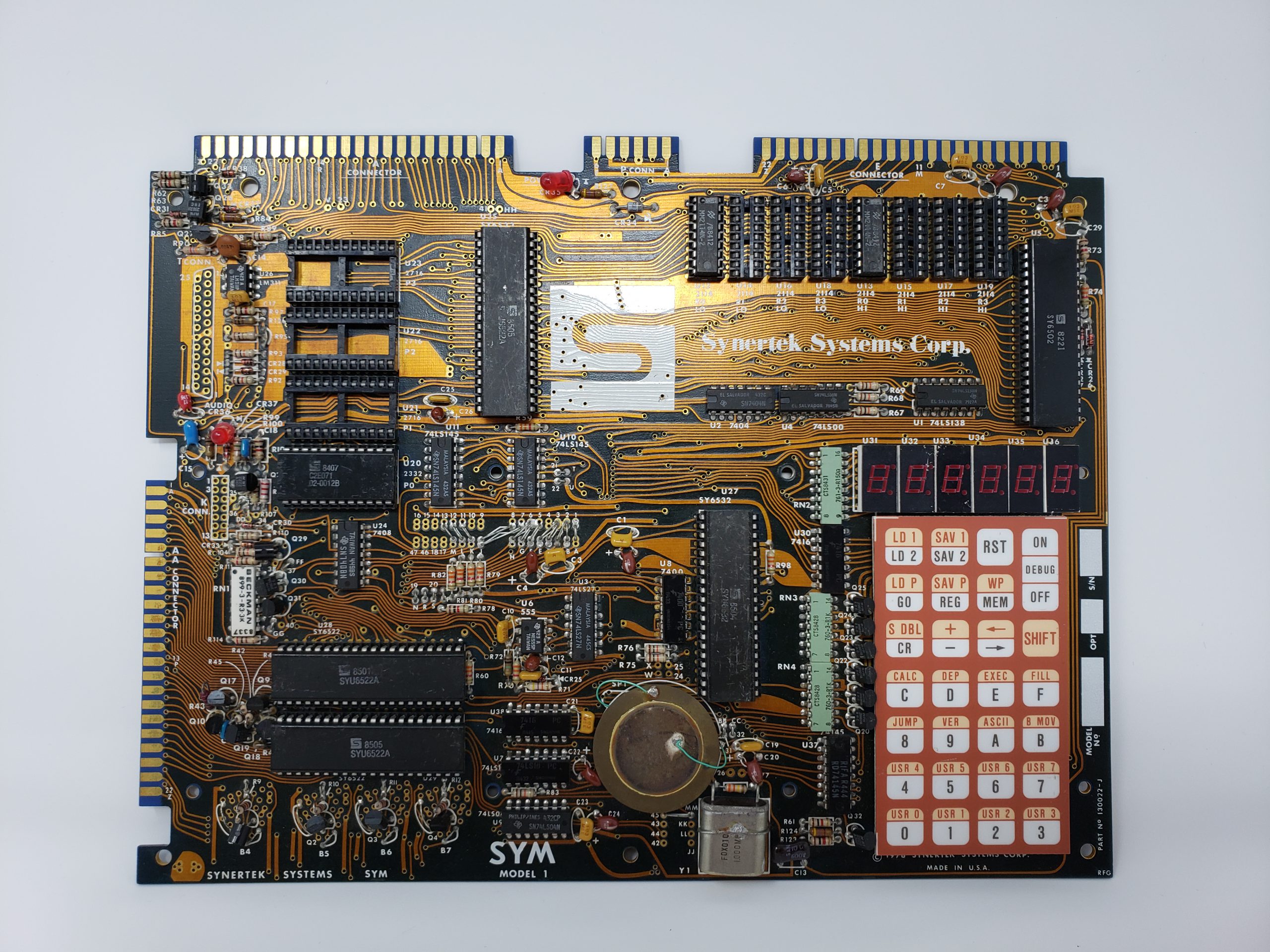
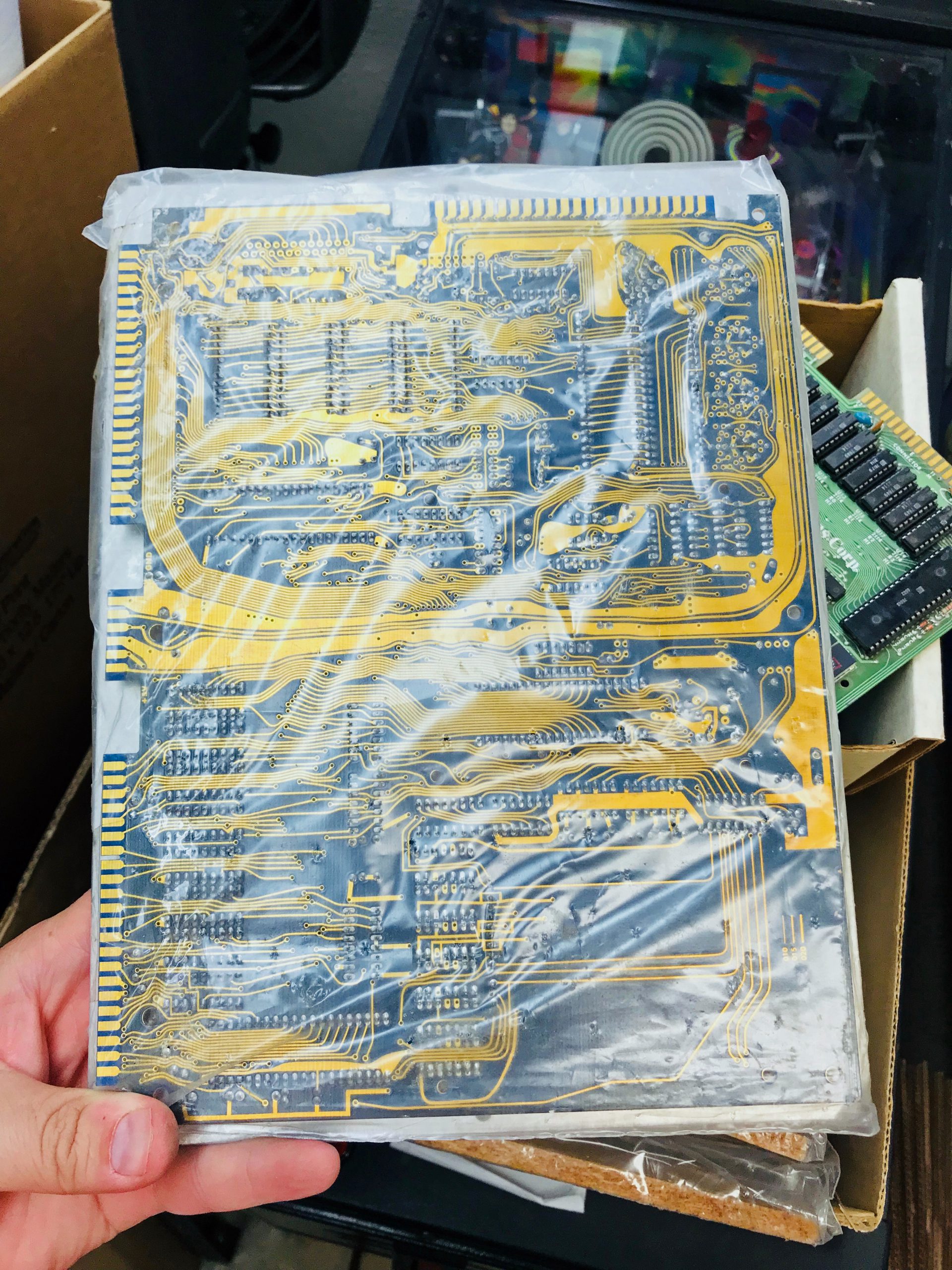
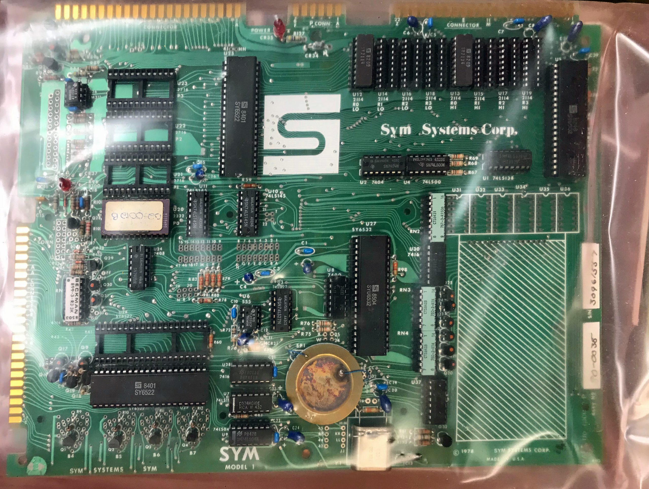
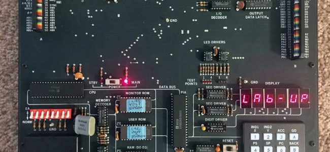
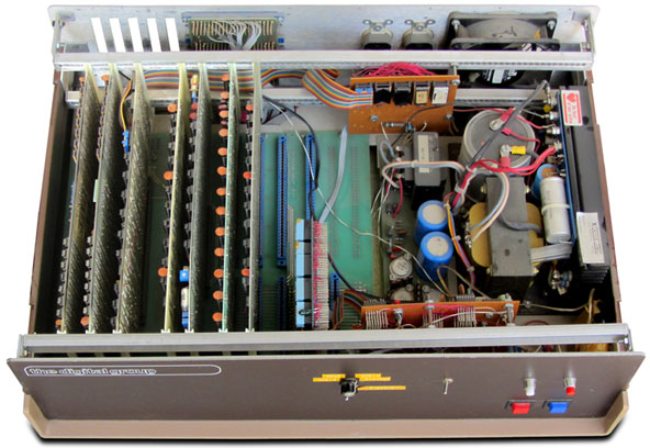
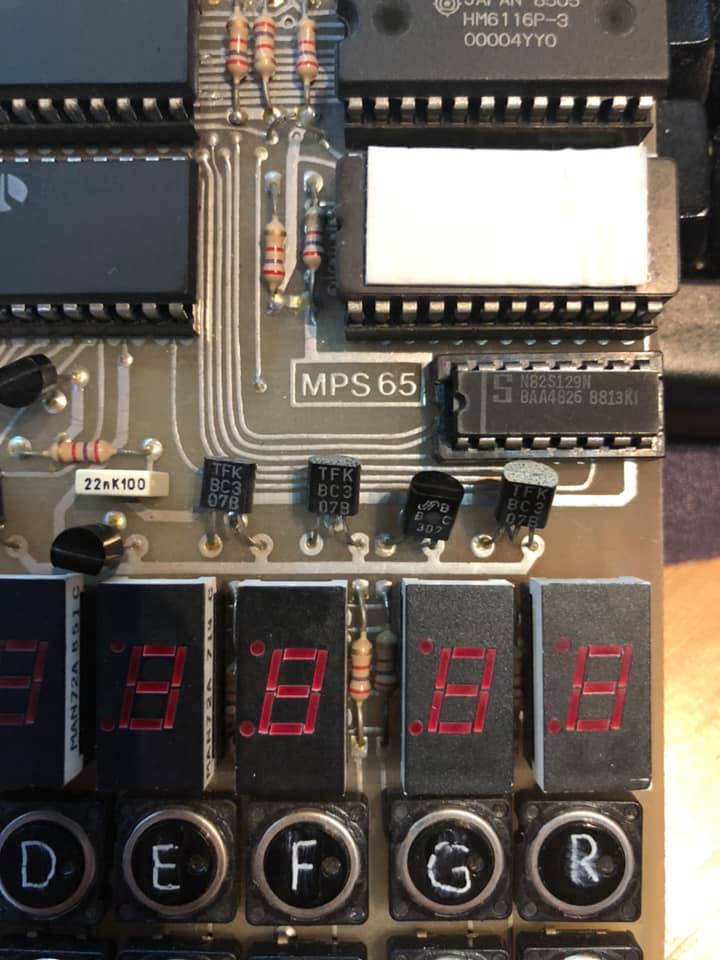
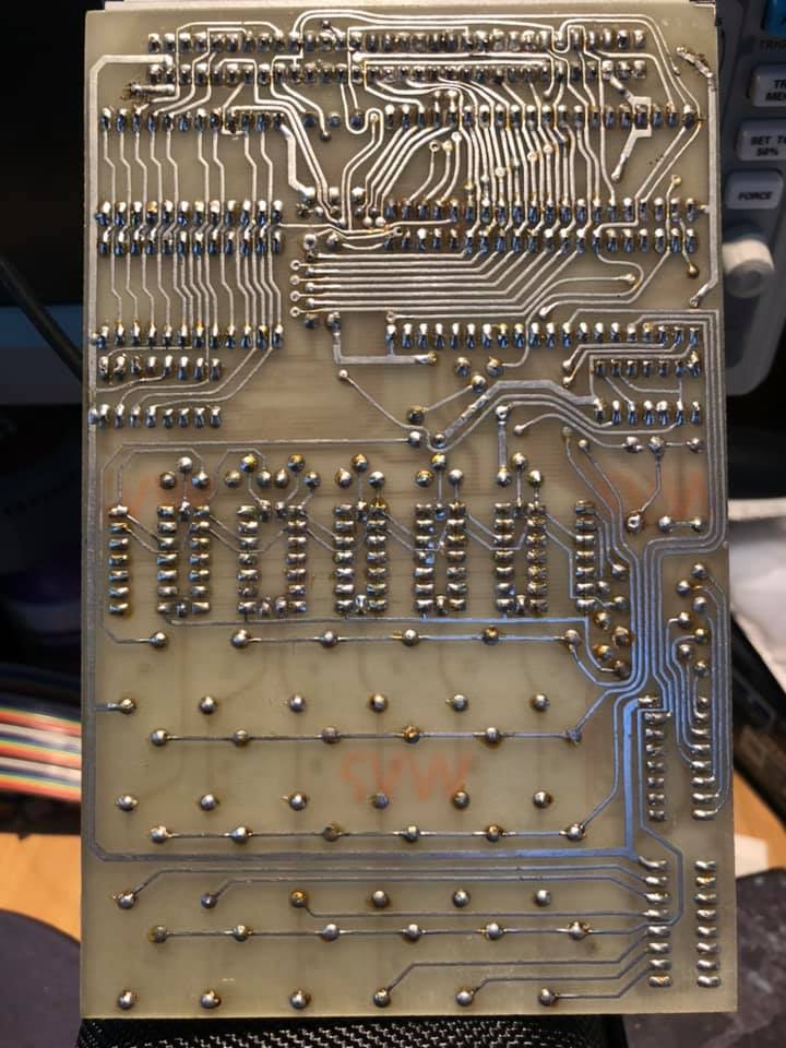
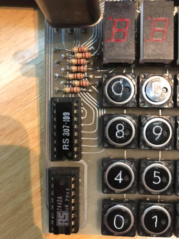
My current SYM-1:
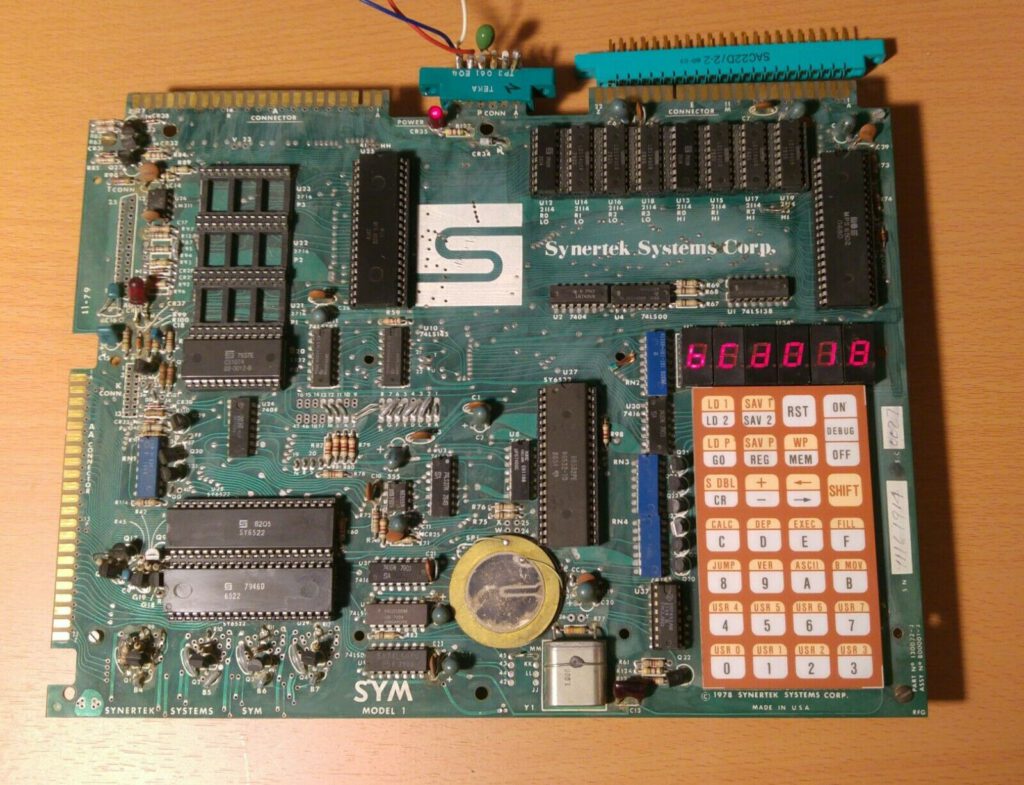
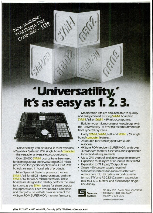


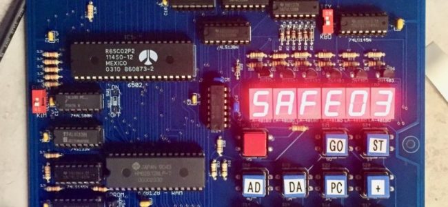
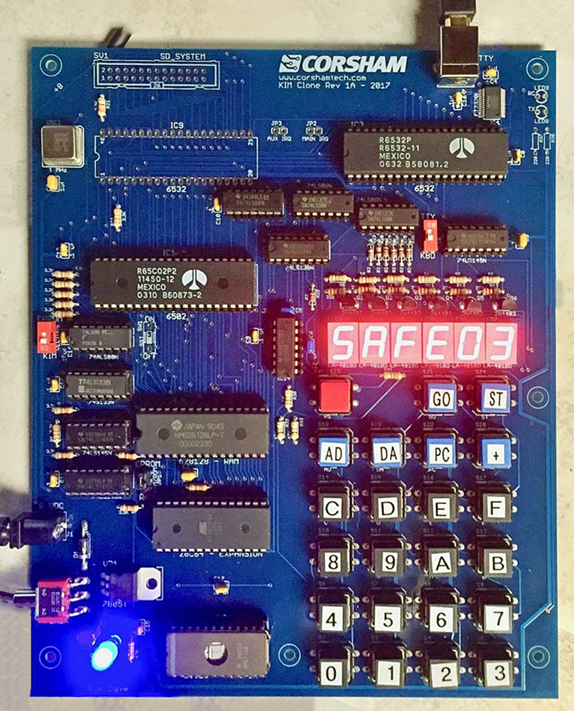
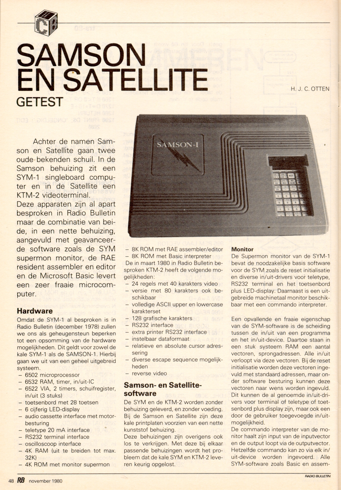
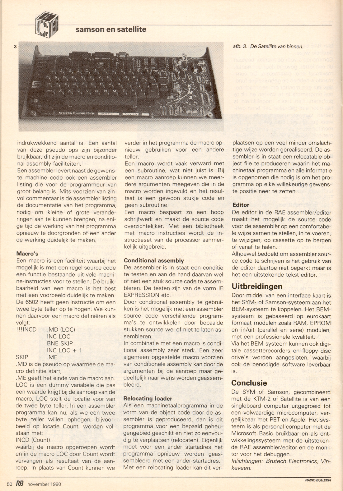
Synertek acquired Microcomputer Associates, Incorporated, consisting of engineers Manny Lemas and Ray Holt, after which it was renamed Synertek Systems, Inc. and established as a subsidiary. In 1978, Synertek Systems released a 6502-based single board computer/evaluation kit called the SYM-1, a derivative of MOS Technology/Commodore Semiconductor Group’s KIM-1.
Synertek’s semiconductor fabrication plant in Santa Clara, California operated from 1974 to 1985. Sometime after 1979, Synertek was acquired by Honeywell and set up as a subsidiary. Later, around 1983, construction began for an additional manufacturing facility in Santa Cruz, California. There was Superfund attention to pollution at the Synertek factory site. When market conditions deteriorated, primarily because of business downturns at Atari, work was stopped at the Santa Cruz facility and it was later sold. Honeywell shut down operations at Synertek in 1985 and assets were sold off (from Wikipedia).
Part of Chapter 5, systems, of the Synertek Databook 1983, note the Jolt was still available.

The end of Synertek Systems in 1985:


Photos by Ray Holt