
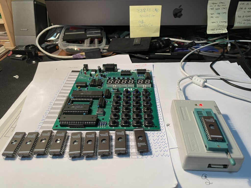
A new KIM-1 clone kit in 2021, the PAL-1. In fact, this is a Micro-KIM clone, which is a KIM-1 clone .. Look and specs are like the Micro-KIM, with some improvements like larger keys and a very affordable price. Motherboard, 32K RAM, second 6532 board, RAM board, ROm board, Cassette board, a full KIM-1 and more compatible system.
Designer and seller is software engineer, Liu Ganning, KJXZZ, from Shenzhen, Guangdong, China
The PAL-1 has its own discussion platform at google groups.
For software: see the KIM-1 software page, as the PAL-1 is a KIM-1 with lots of memory!
PAL-1’s difference
First, PAL-1 is a kit, you can assemble it, test it and run it all by yourself —— an unique experience!
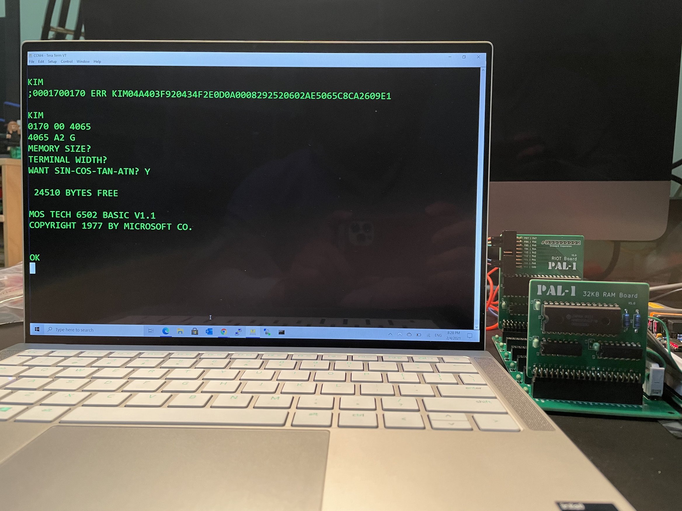
The PAL-1 addressing mode is completely implemented in accordance with the design of KIM-1, so it is compatible with most programs developed on KIM-1.
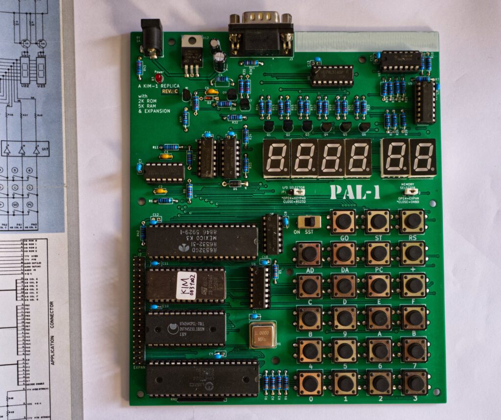
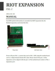
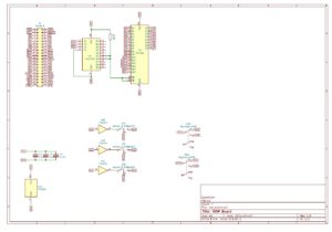
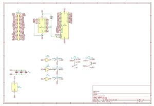
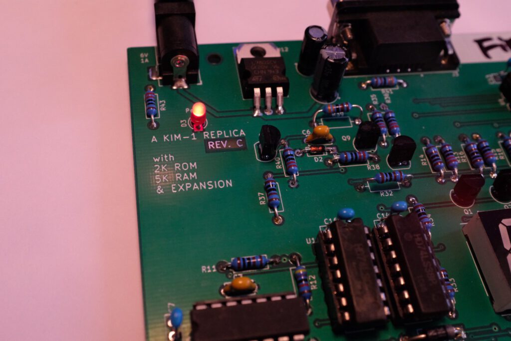
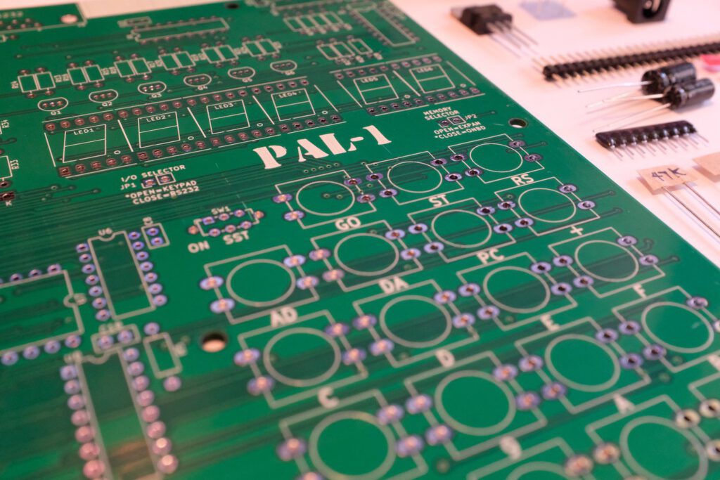
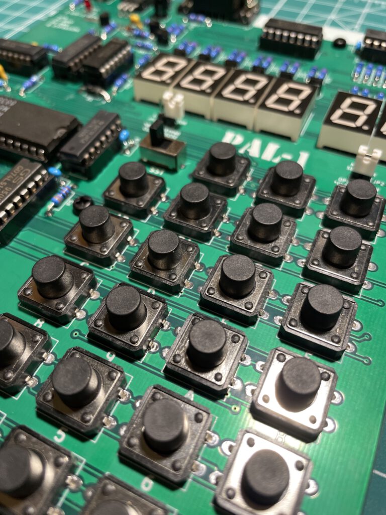
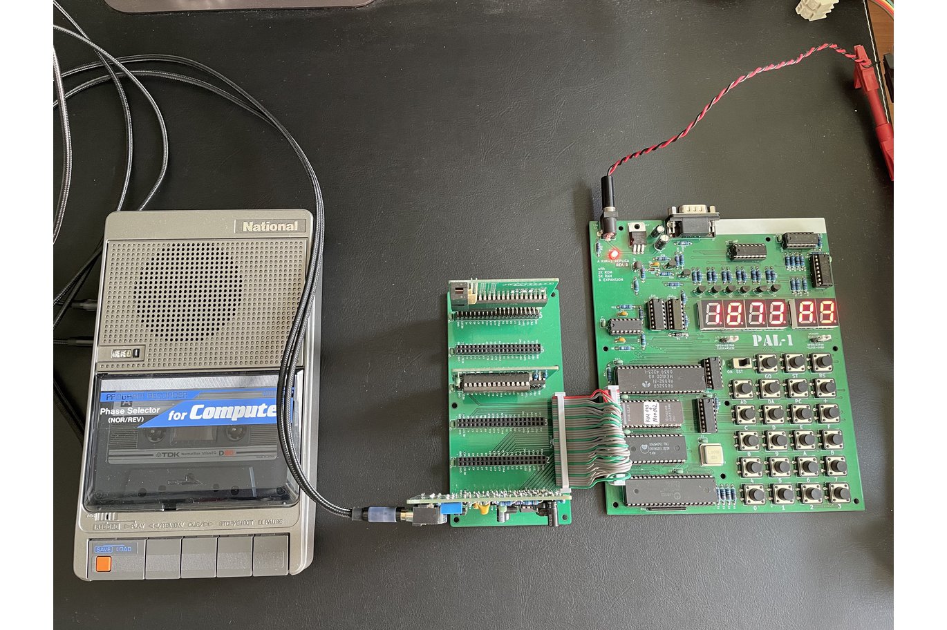
PAL-1 has 2K bytes ROM (complete KIM-1 Monitor), 5K bytes RAM, one 6532 RIOT chip on board, provides two 8-bit bidirectional I/Os, these I/Os are mainly used to support 23-key keyboard input and drive 6 seven-segment LED displays. In addition, PAL-1 also provides RS232 serial port to support terminal operation and 40-pin expansion port for future upgrade. The TTY/RS232 interface and expansion interface pinout uses the design of Rich Dreher and Vince Briel (MicroKIM compatible).
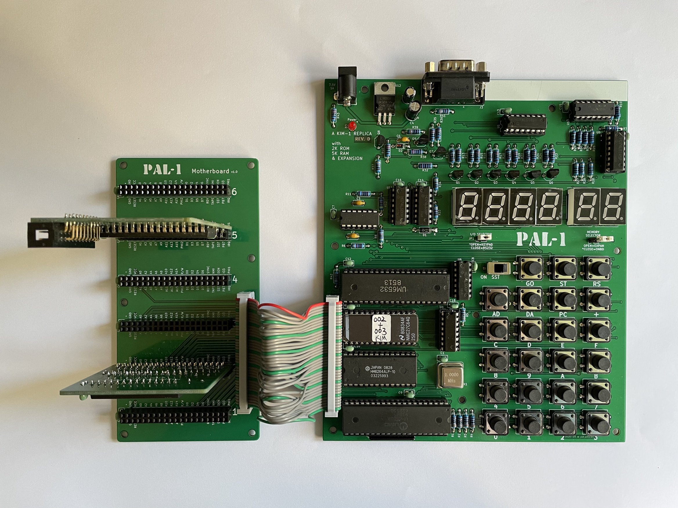
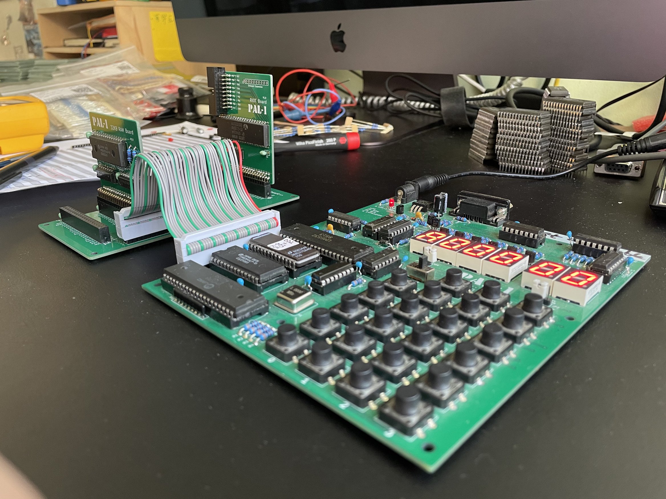
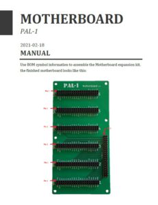
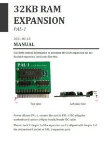
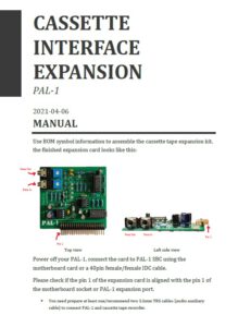
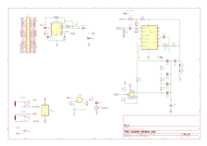
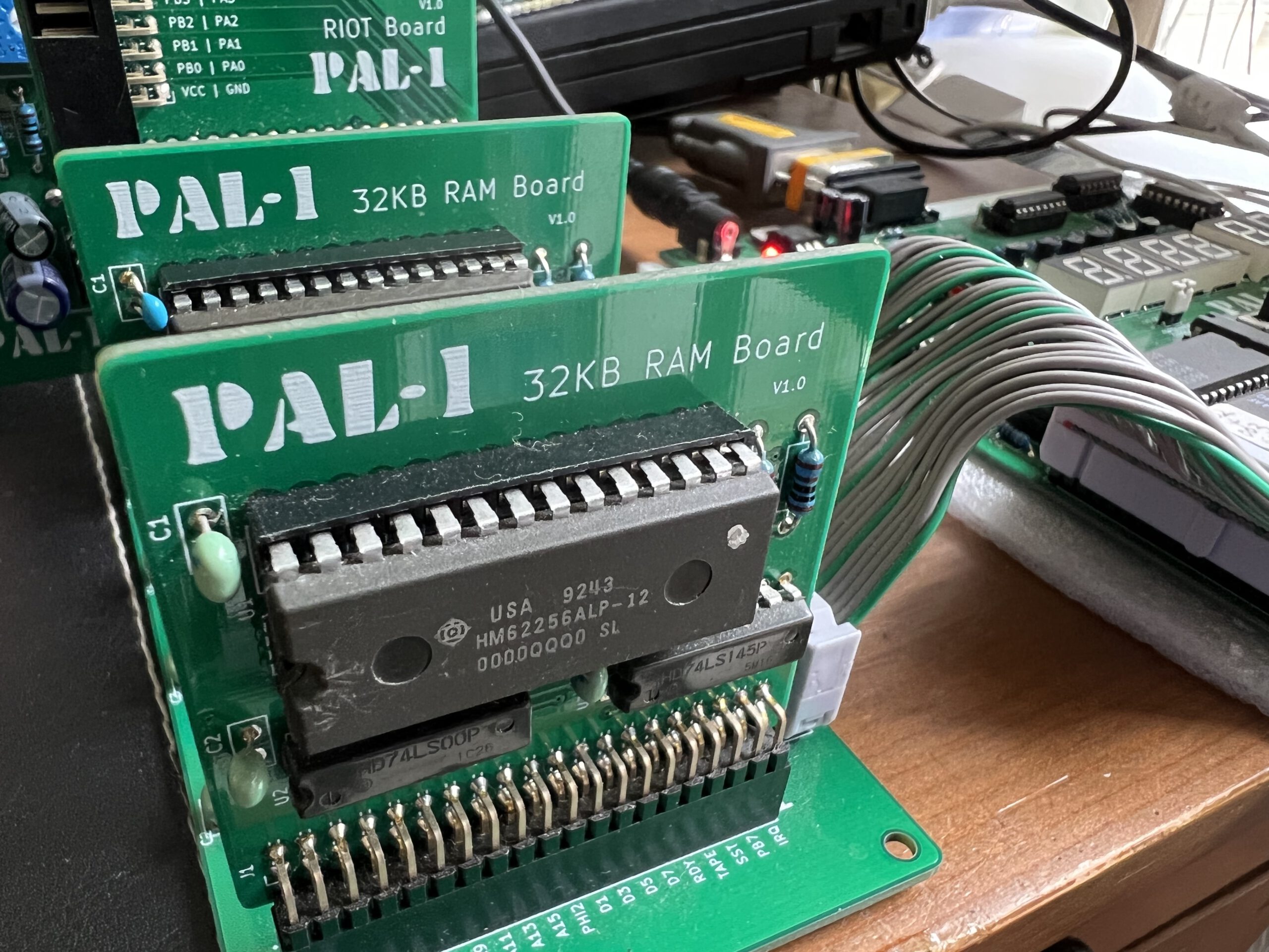
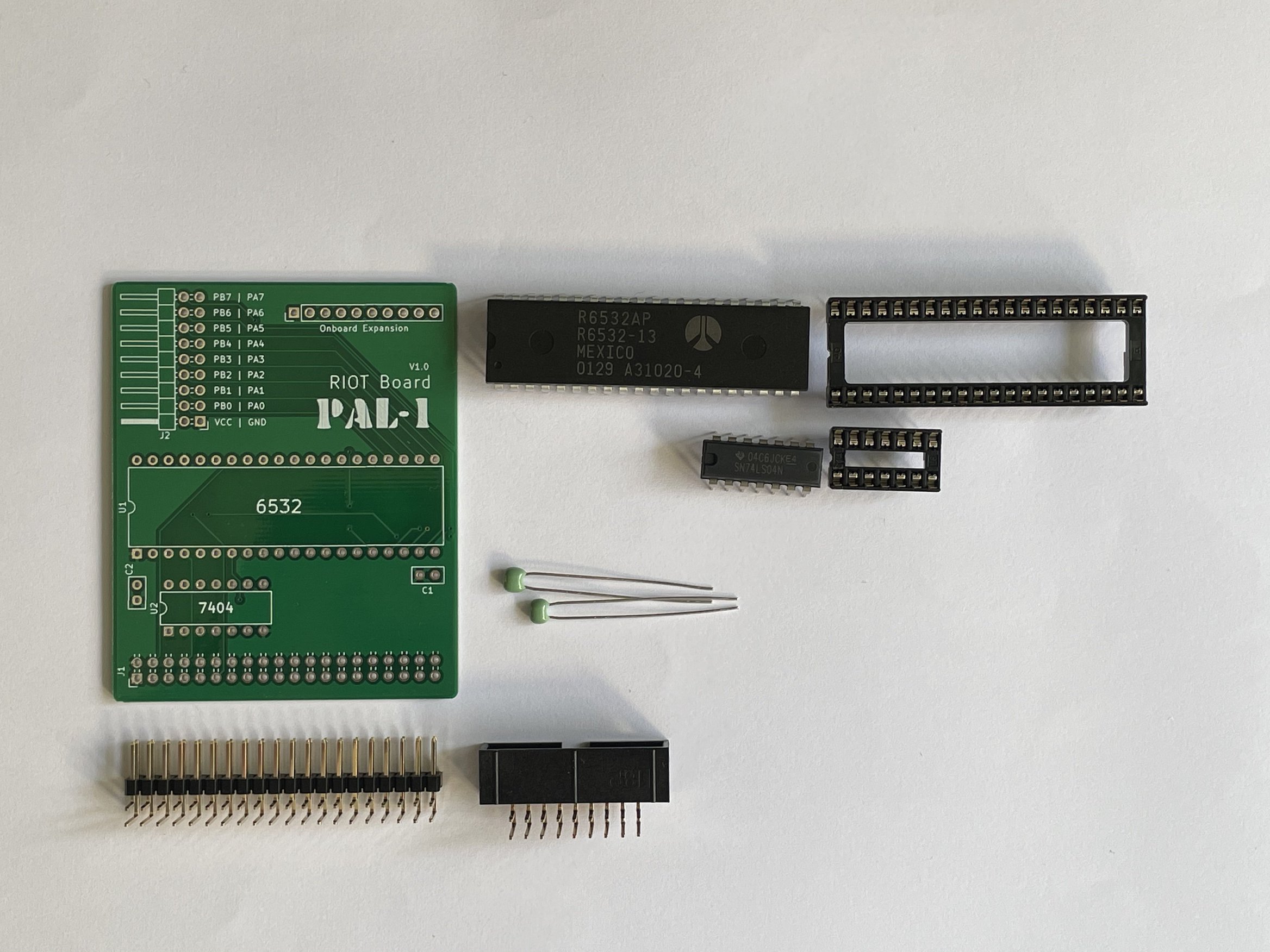
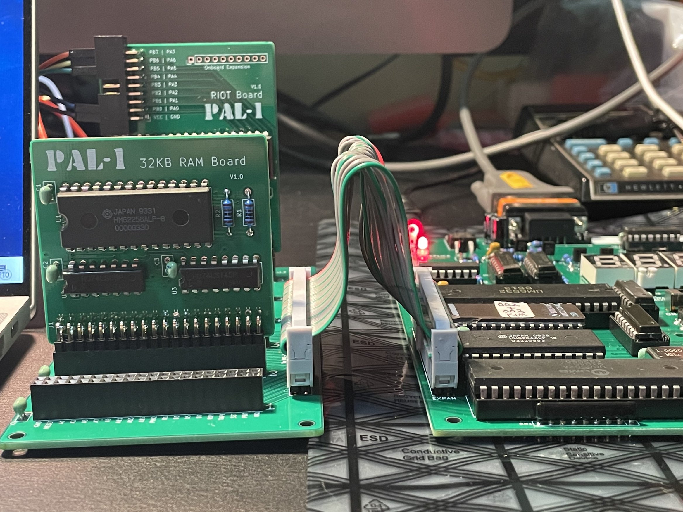
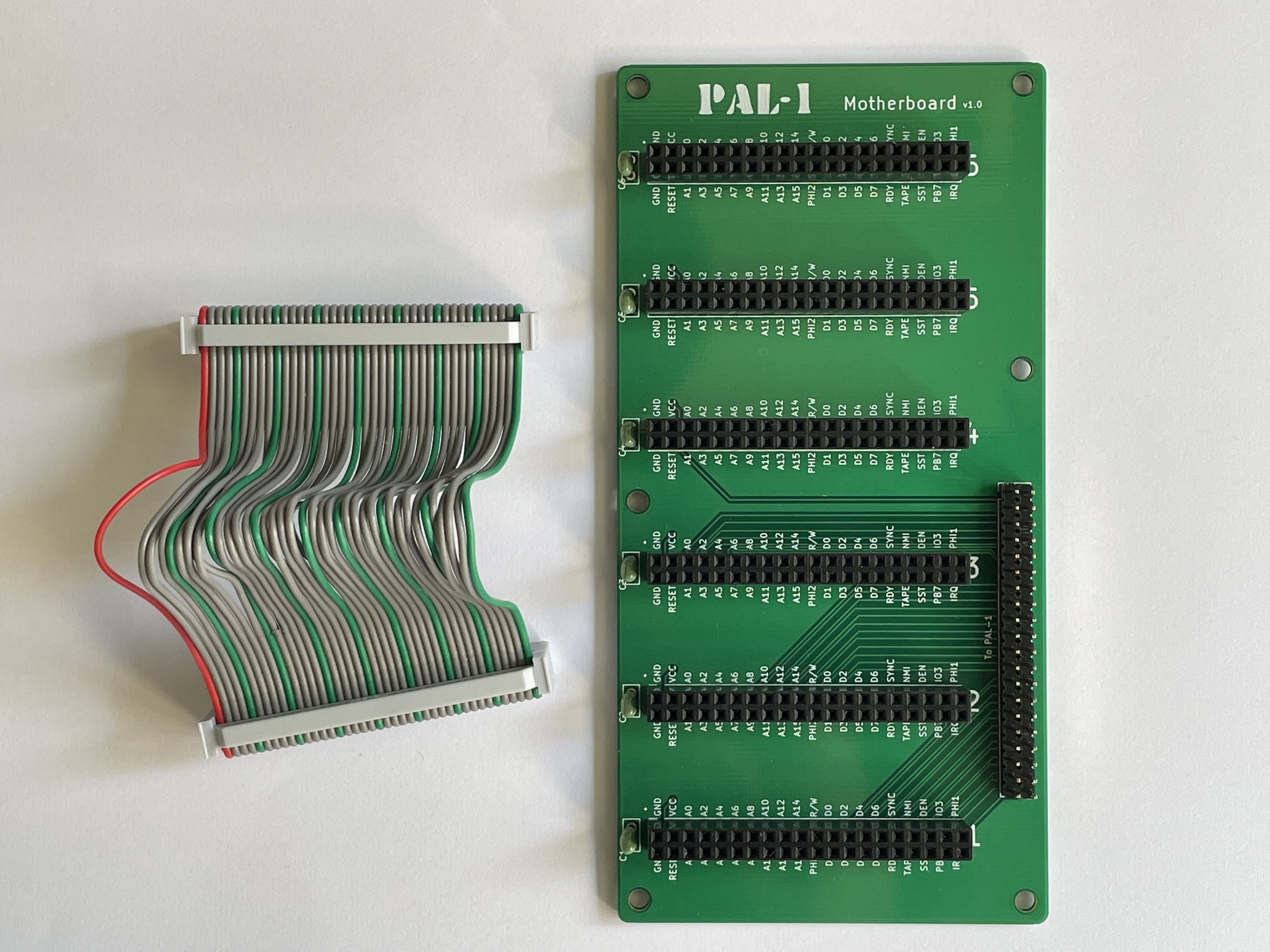
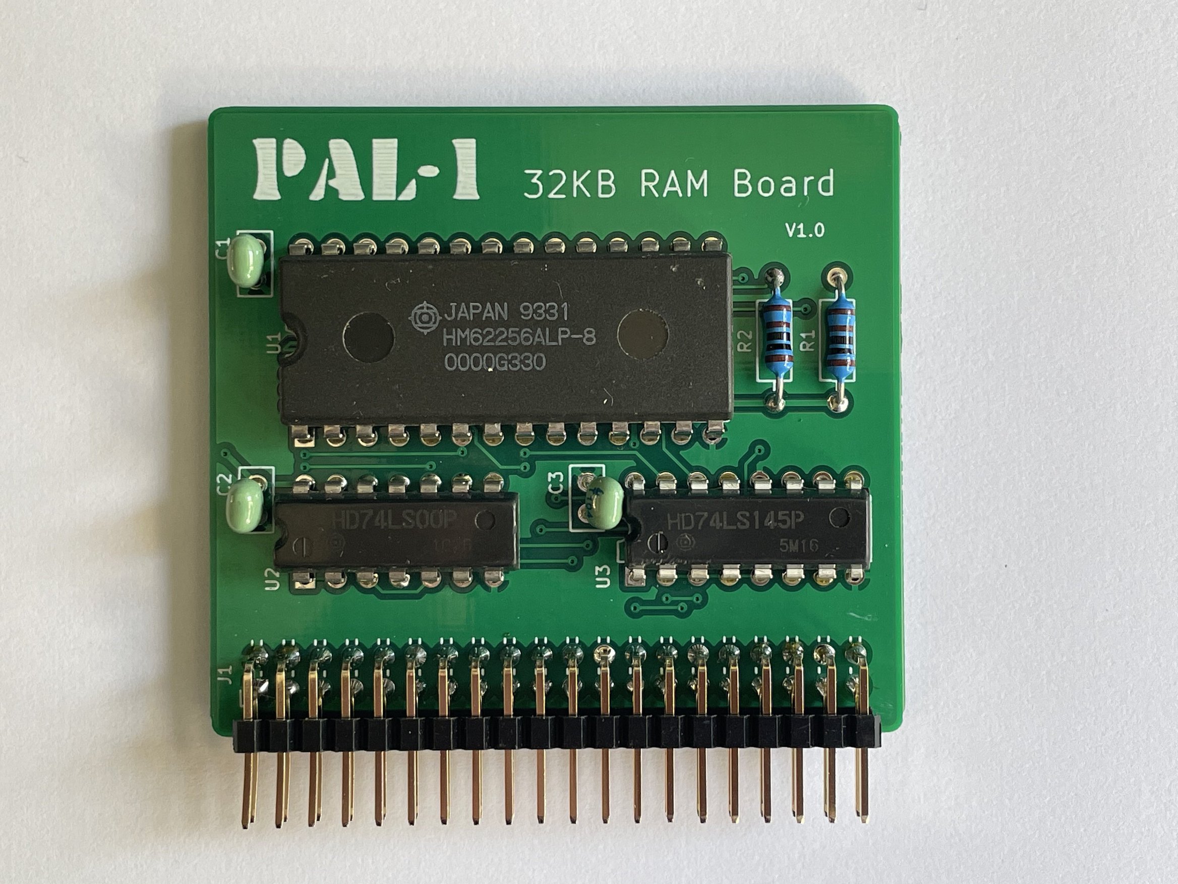
Besides the PAL-1 also a 6 slot motherboard, a 32K RAM board and a RIOT board (the second 6532 making it a complete KIM-1) and a cassette interface baord are available. A ROM boards adds many programs like programming languages Basic, Forth etc.
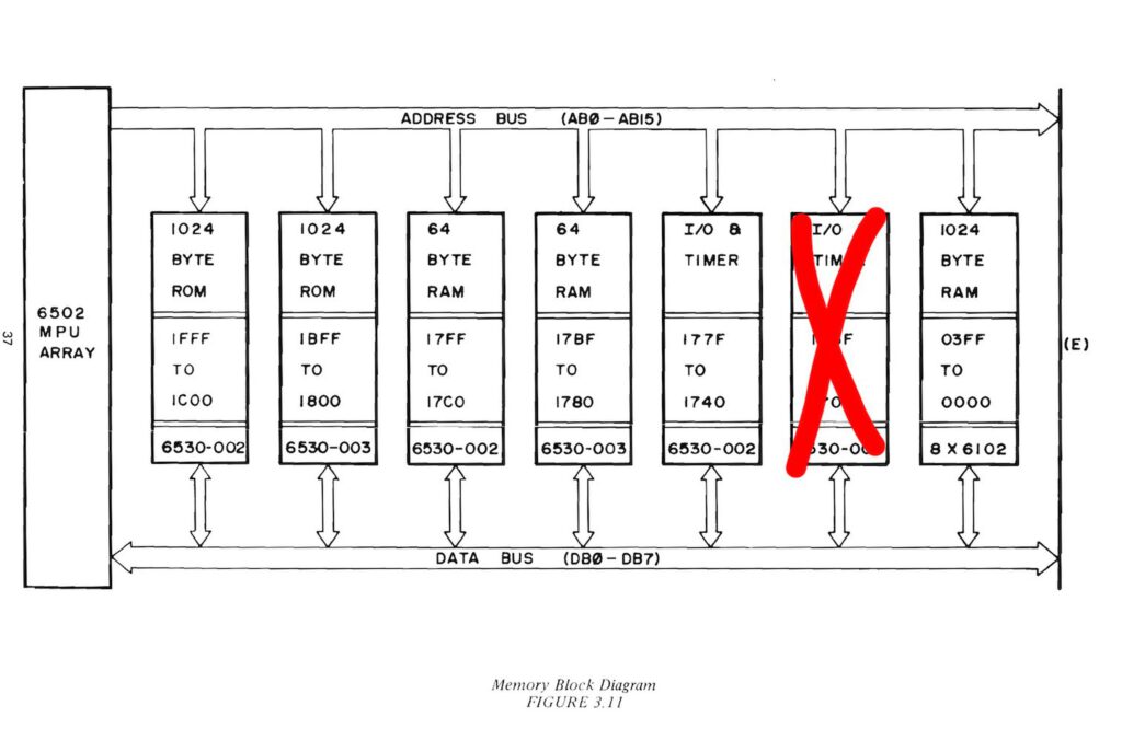
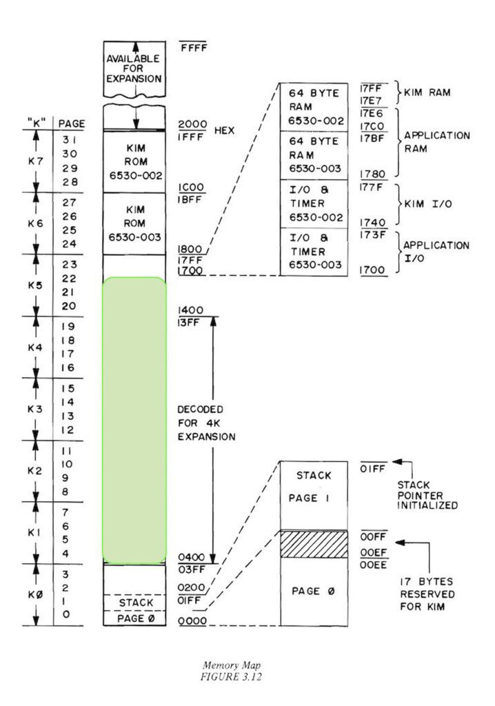
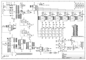
The main differences between PAL-1 and KIM-1 are illustrated by the following two figures in the “KIM-1 User Manual”.
PAL-1 absence half I/O and Timer (red) Picture 11 (see the RIOT board how to add this!)
PAL-1 onboard RAM increased to 5K (all green spaces are available) Picture 10
What is included
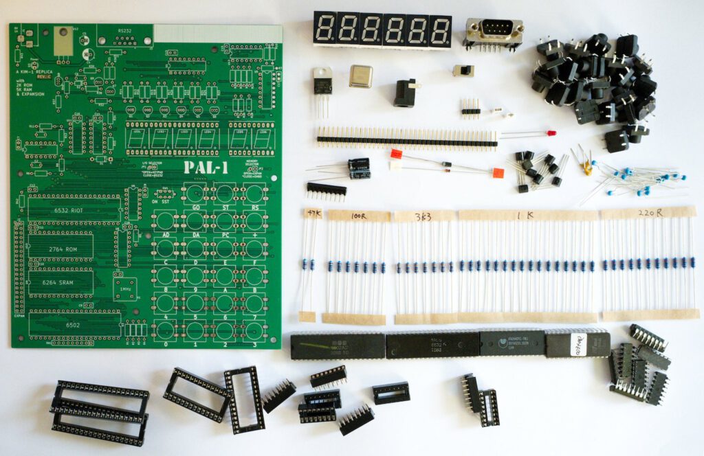
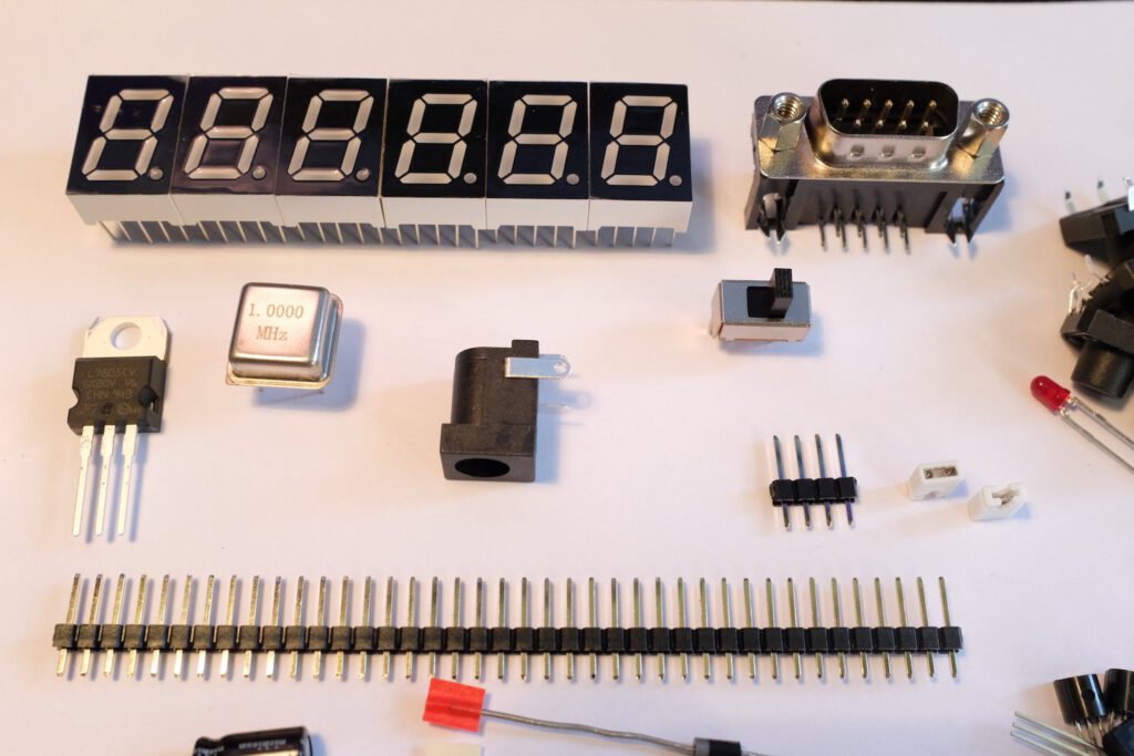
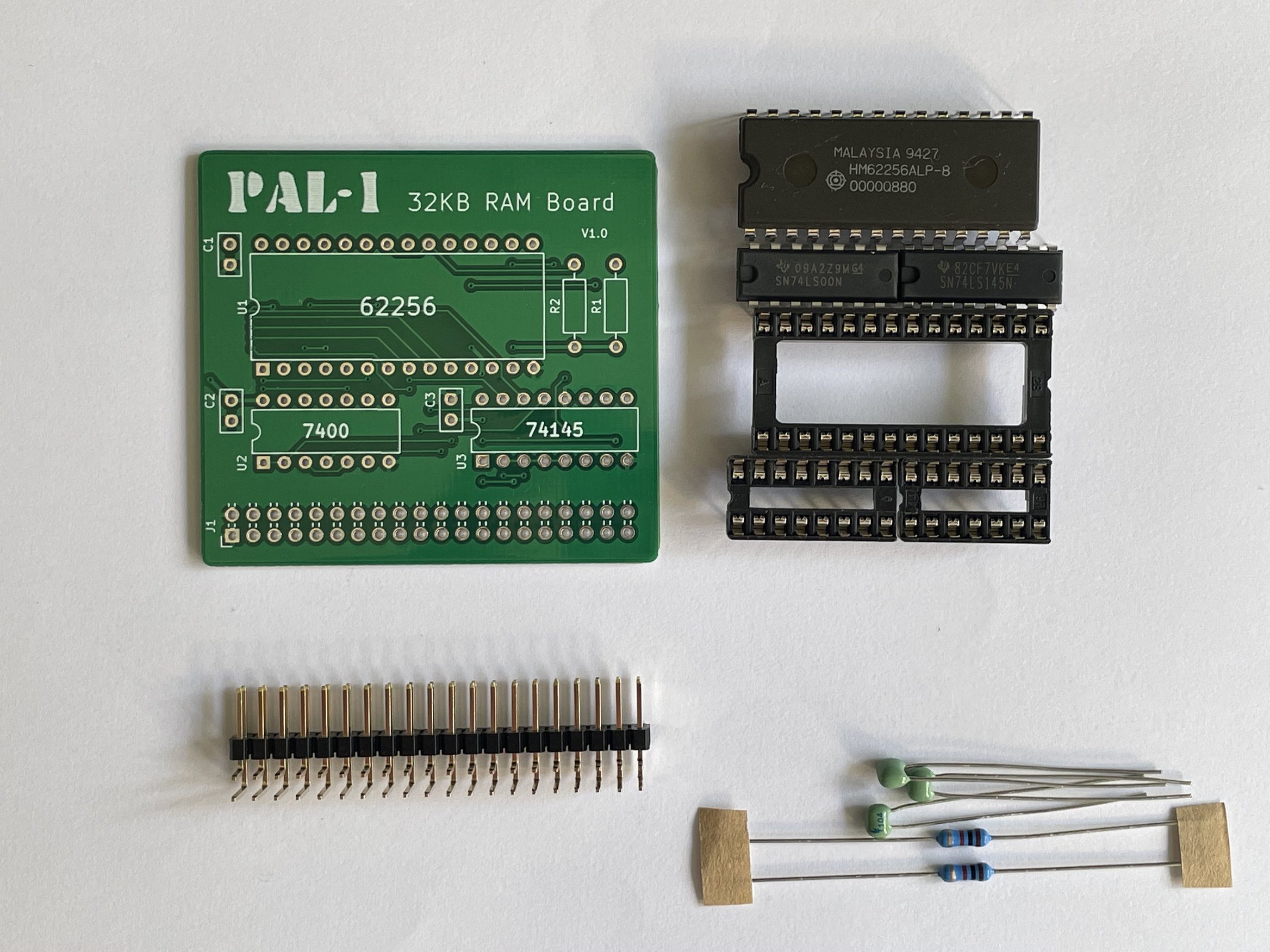
The PAL-1 Kit includes mainboard PCB, ICs, pre-programmed ROM, passive components, sockets & headers.
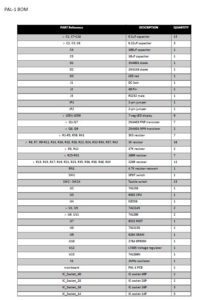
Print version BOM, Pinout, Schematic.
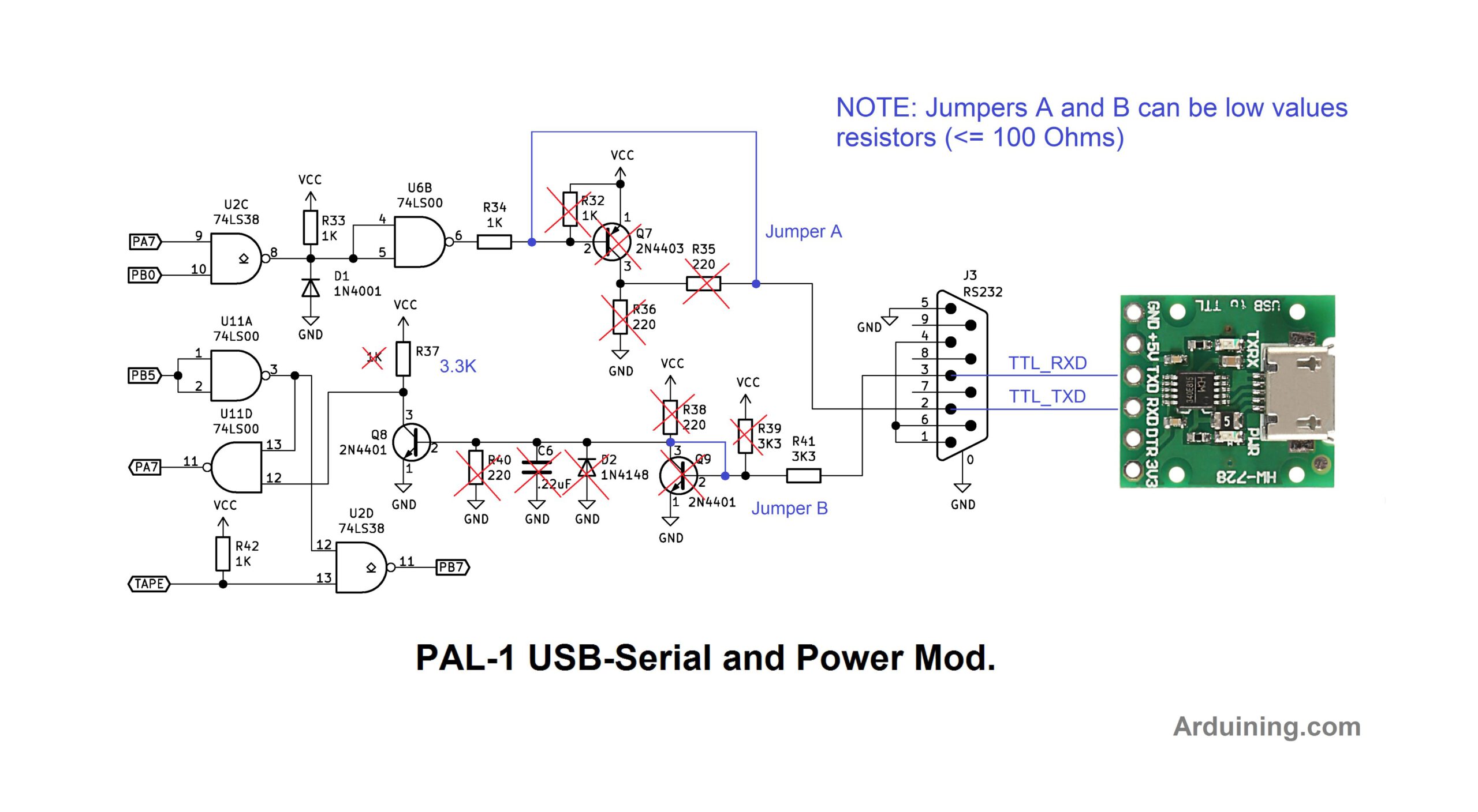
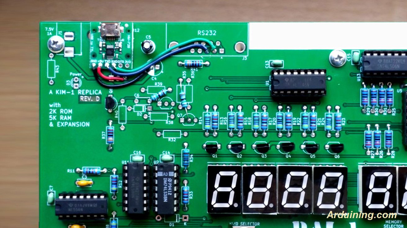
Modification for TTL USB interface
The two following images show how to adapt the PAL-1 to a TTL USB interface instead of RS232. also supplying power from USB.

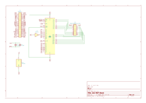
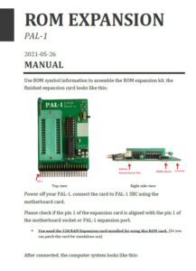
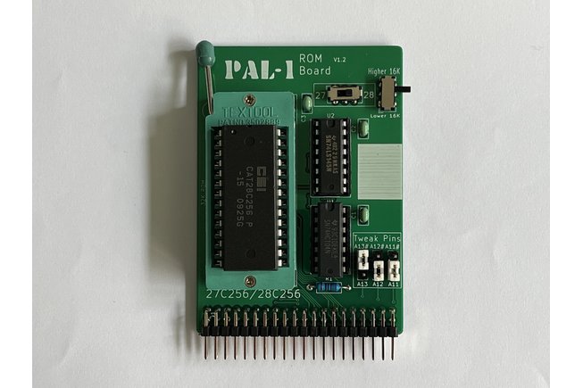
Modification of ROM board 1.0 for 28C256 EEPROM
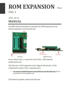
The ROM card v1.0 is designed for using 27C256 and 27C512 EPROM, but these UV-erase chip will need much patient when you’re doing a lot of ROM program. So the PAL-1 got a new version ROM card, v1.2, to support the more convenience EEPROM, the 28C256.
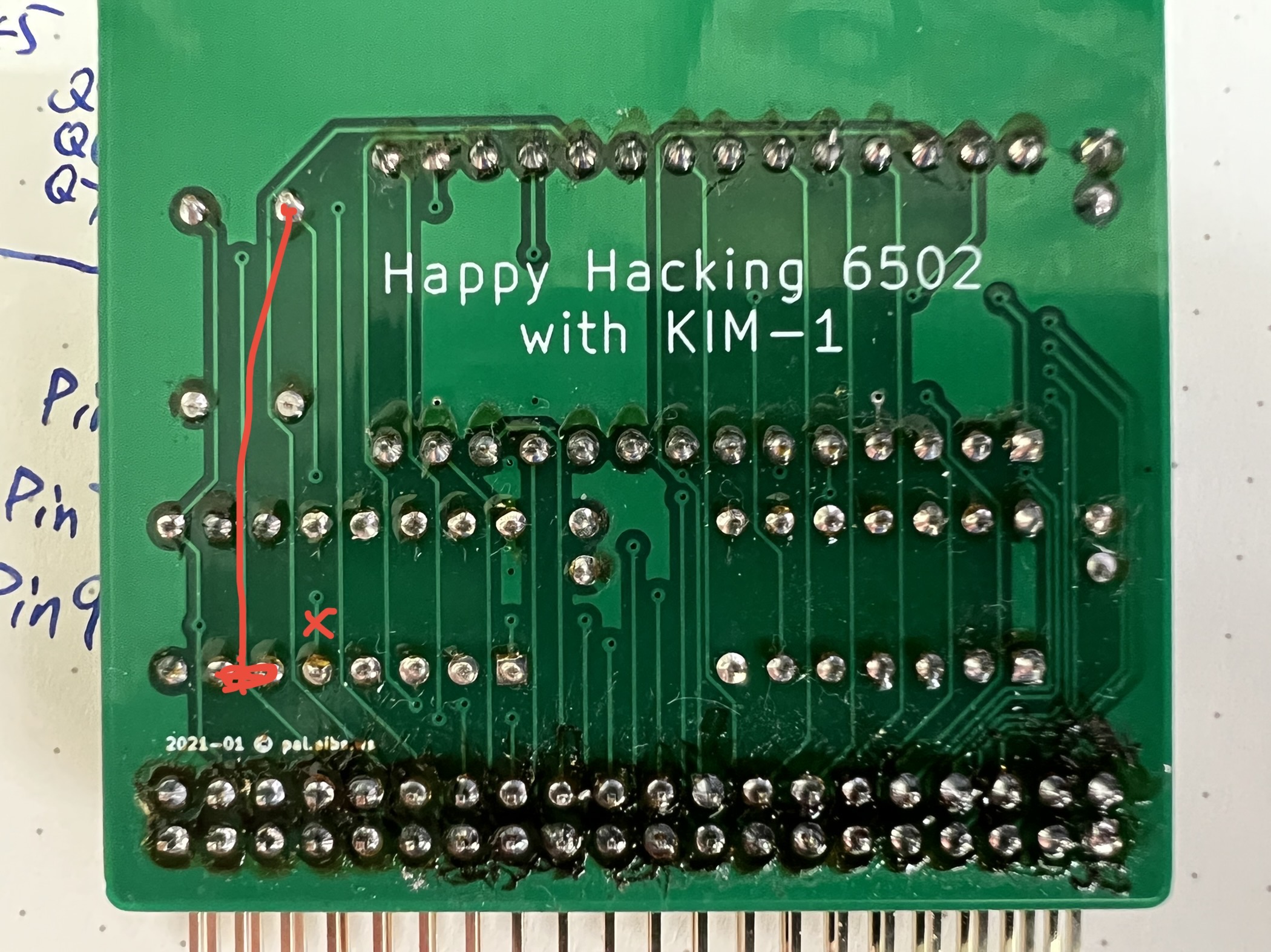
Even the v1.0 ROM card designed for the 27Cxxx, you can also use the 28C256 on it. Just one soldering work need to do, populate the high 32K switch using a switch (like K3-2235D-F1) or 3-pin 2.54mm pin header (solder at the inner side of the high 32K switch).
When you need to using a 28C256, you can set and keep the low 32K switch to HIGH, then using the high 32K switch/jumper to select the low 16K bank or the high 16K bank of 28C256 just like normal.
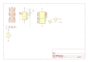
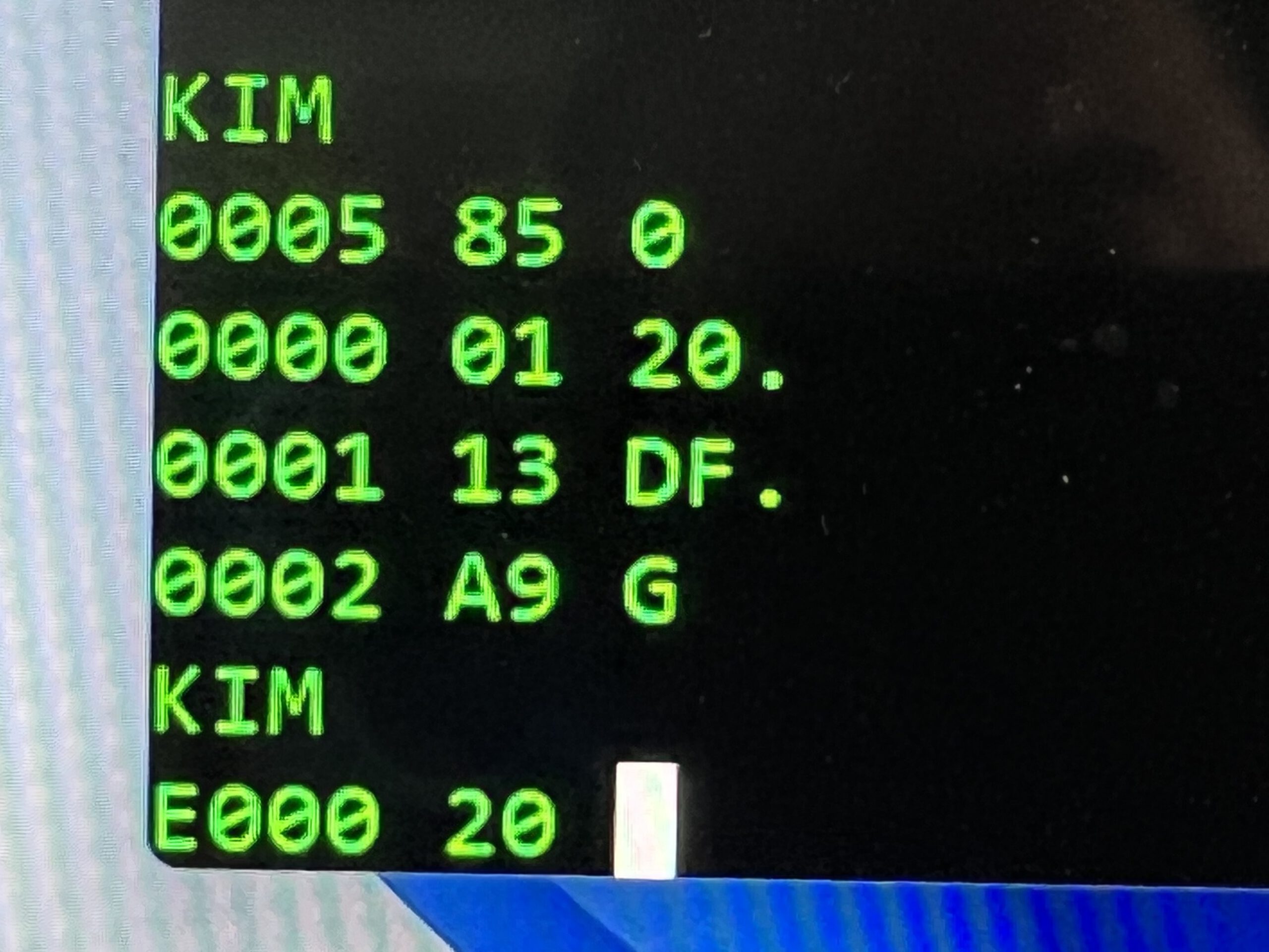
A second RAM board can be modified to add 16K extra. Some pictures of the two RAM card system running. RAM test: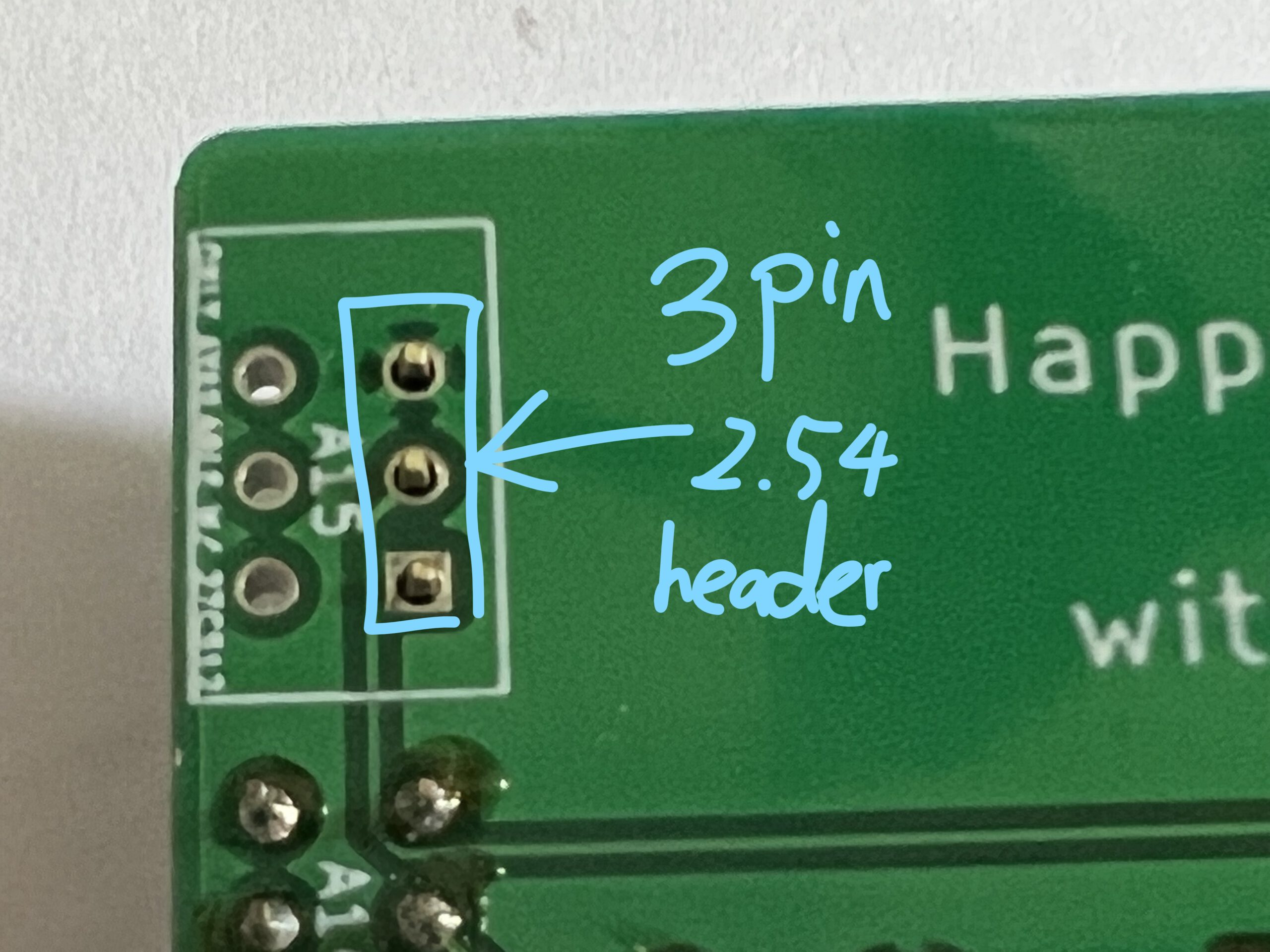
Modify a 32K RAM card for the upper RAM area. Just need to cut 1 wire and solder 2 jumper wires like below:
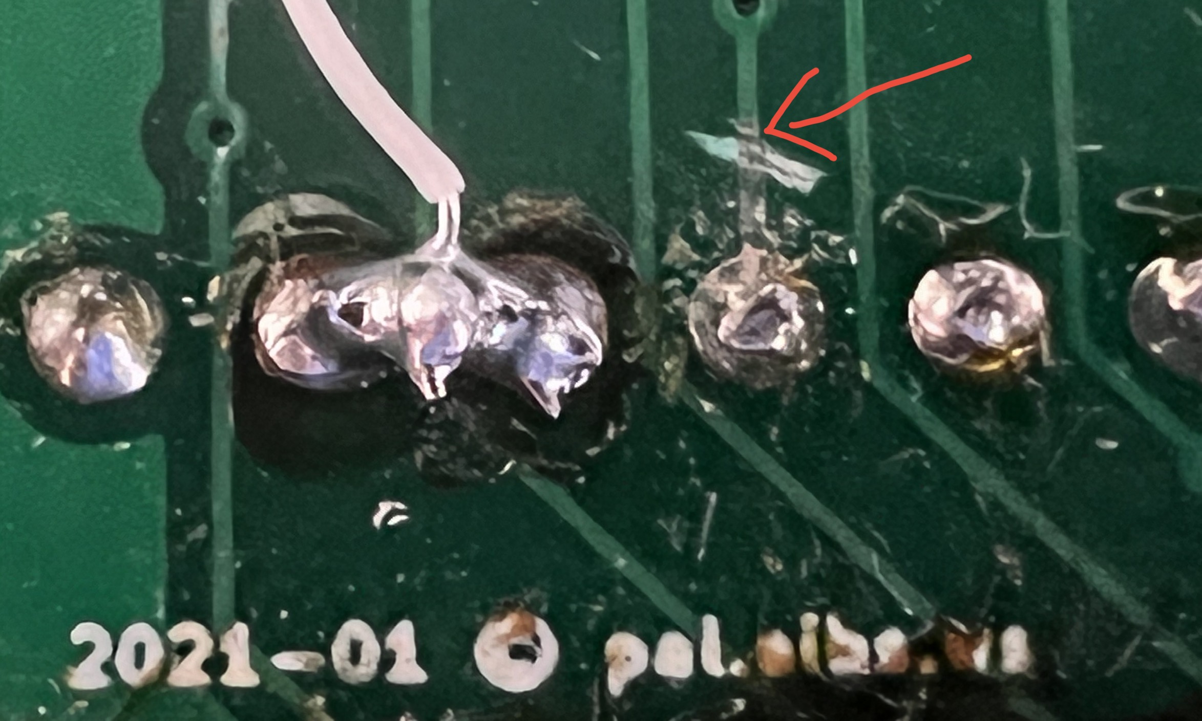
The KIM ROM needs the highest area of 64K for the vectors, so the Exxx to FFFF cannot be decoded with the second 32K RAM card.
We can use $A000~$DFFF (16K) more RAM with the second RAM card installed.

See also:
Jolt Replica by Eduardo Casino
MTU K-1008 Visible Memory
TTY Serial
TTY Console