Beta computer
Original articles on the Beta appeared in 1984 in the popular-scientific magazine Kijk (which means ‘Look’ or ‘Watch’).
Design and articles by Steven Bolt, Pitronics. All rights reserved, this publication by permission of Mr Bolt.
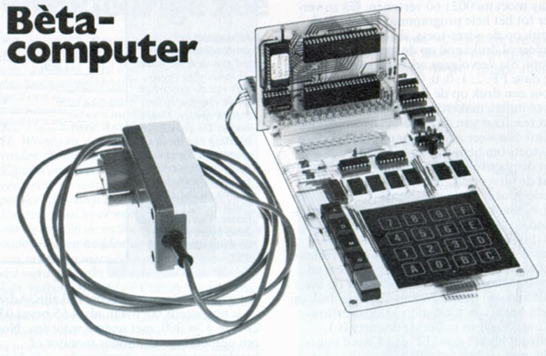
The Beta computer is a small but fully functional 6502 system. Ideal for controlling applications! The base, called ‘controller’, is a PCB with 6502 cpu, a 6532 RIOT and a 2716 EPROM. A really minimal 6502 system with lots of I/O and a minimal IC count. This standard controller is meant to be inserted in a PCB called ‘terminal’ on which specific hardware can be placed, depending on the application.
Two ‘terminals’ have been described in the original articles, one acting as a development system, with KIM-1 like seven segment LED display, hex keyboard and an EPROM programmer. The second ‘terminal is a smaller board with a relay to switch a load and temperature sensor and also a keyboard and LED display. Besides the original articles, scanned and in dutch, the most relevant information of this system is shown in english, including source of the monitor.
Downloads:
- Dutch article series 1984
- Original source, scanned from paper
- Beta Monitor, source, and binary
- Article 1984 hires scan, tnx G. de Bouter
The Robot Arm
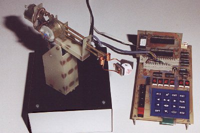
Here you can see the Beta computer put to work. Controlling a robot arm is a job a 6502 based machine like the Beta can do very well.
Beta controller
A minimal system, 6502, 6532 RIOT for I/O, timer and 128 byte RAM (zero page, stack, program memory, mapped all from address 0000) and a 2716 EPROM for a control program like the Beta monitor.
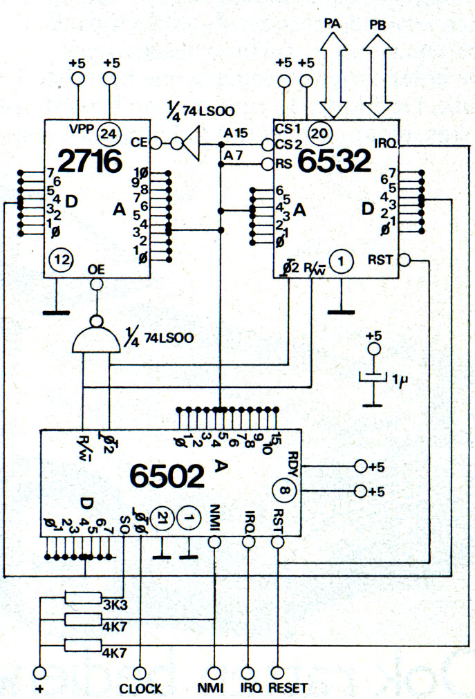
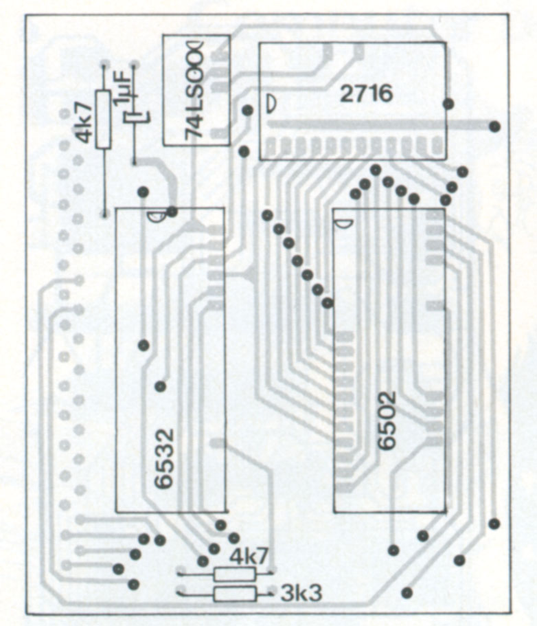
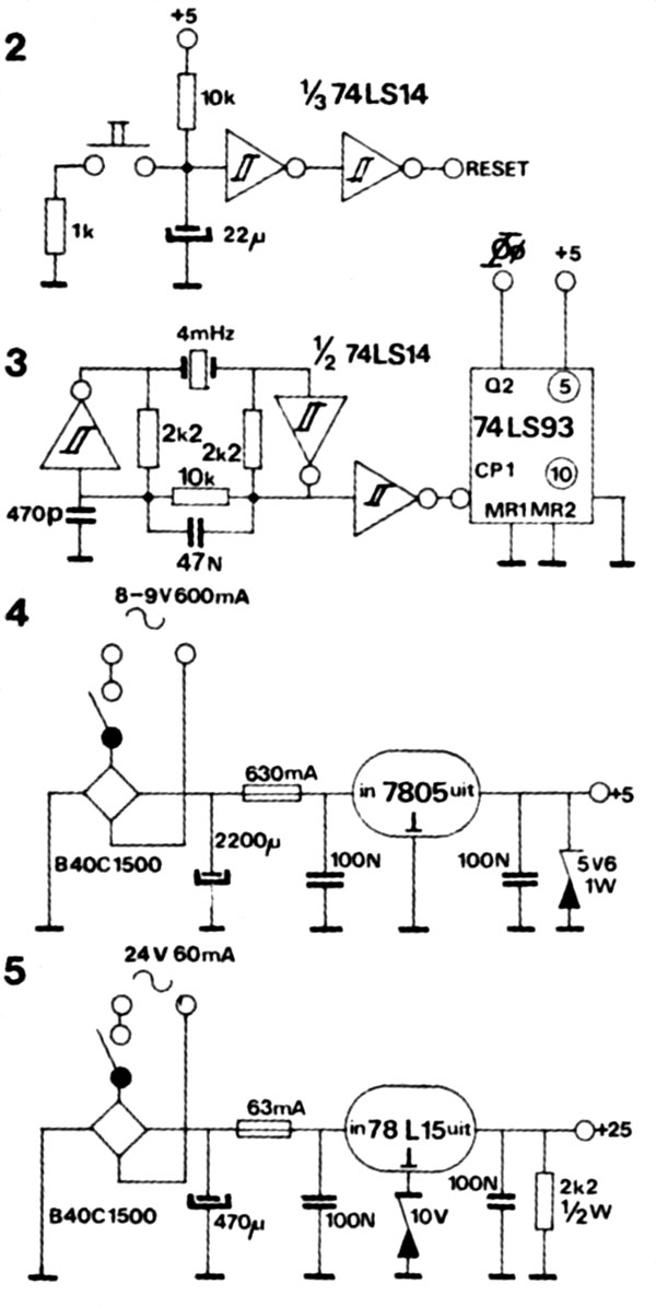
As you can see, a minimal system. To make it as universal as possible this controller needs an external clock, a Reset circuit and a power supply to start.
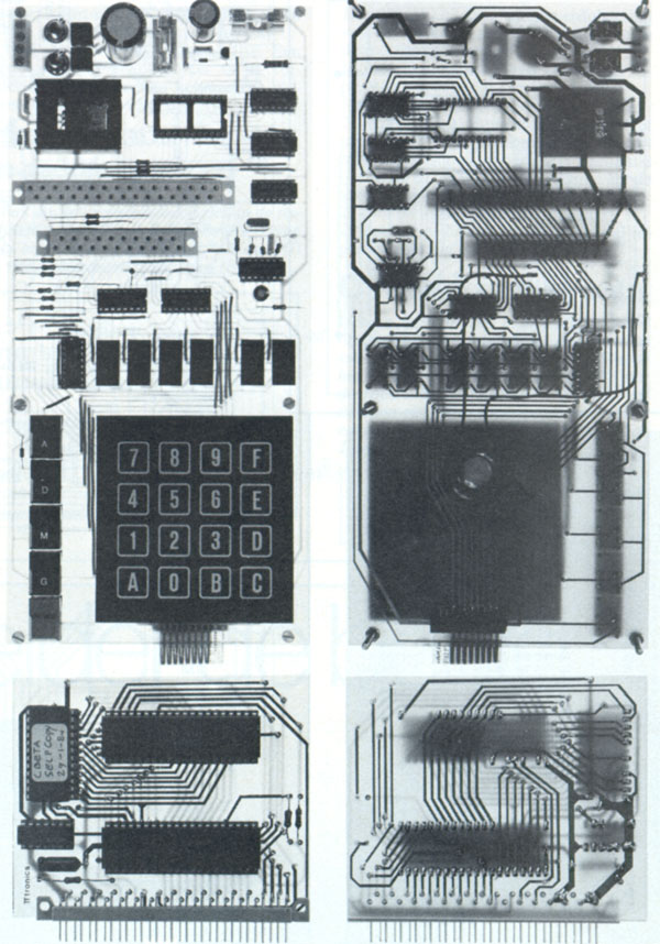
Terminal for development
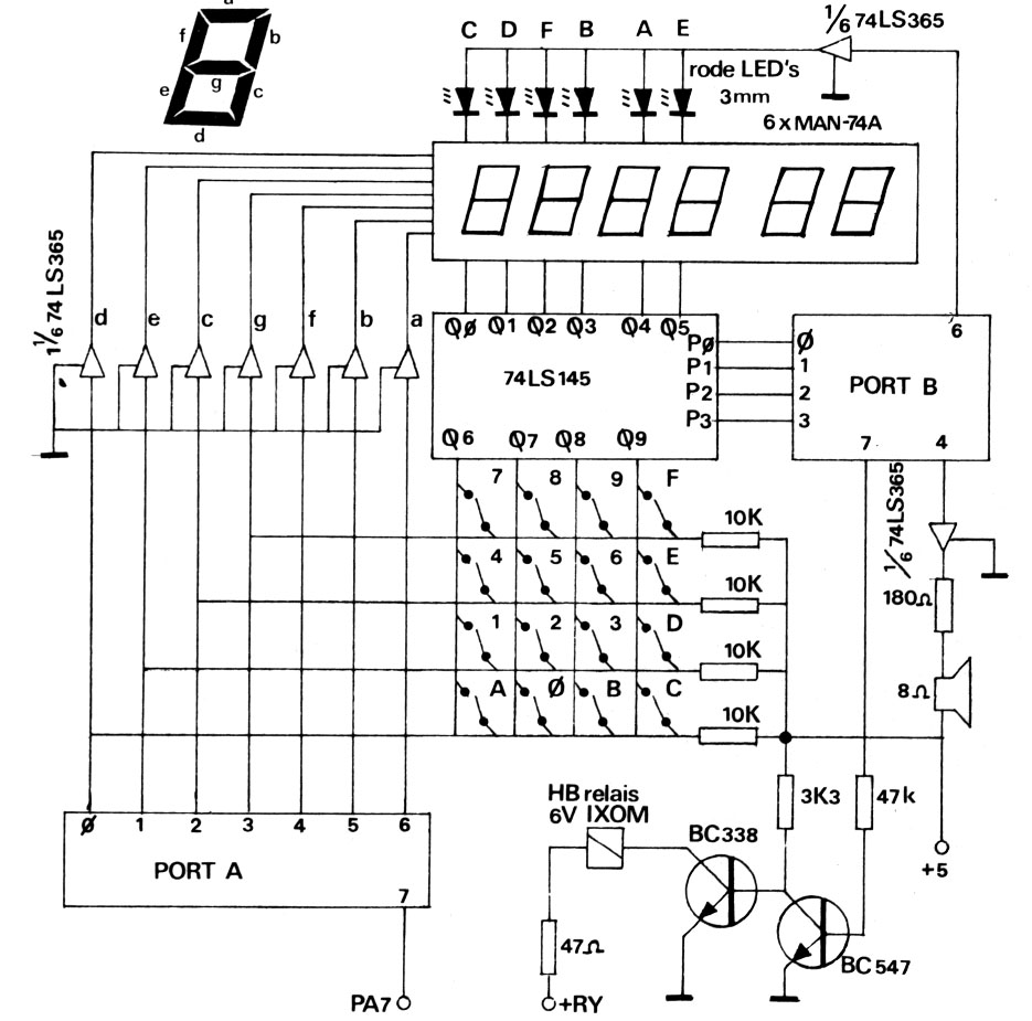
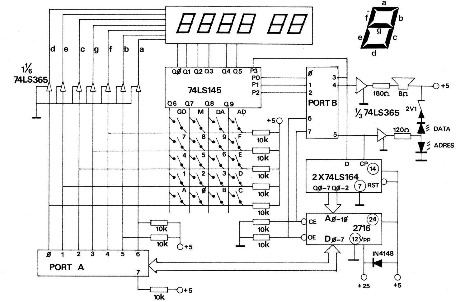
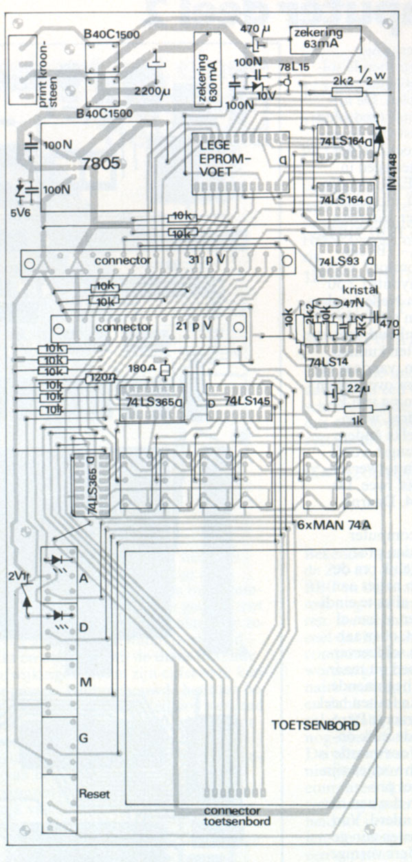
The development system for the beta monitor has a hexadecimal keyboard , six hex digit LED displays, keys for A(ddress), D(ata), G(o)and a Reset key.
After resetting the Beta with the Reset key and pressing G the Beta monitor is atarted. With the A and D keys (with LEDs showing the current A or D choice) and the hexadecimal keyboard, addresss and data can be selected and dsiplayed and data stored. With the G(o) key a program at the selected address is started.
| The memory map | 6532 RIOT | ||
| 0000 | monitorvariables | Data Register A | 0080 |
| 0007 | vectors (IRQ, NMI) | Data Direction Register A | 0081 |
| 000B | variables EPROM, BRK | Data Direction Register B | 0082 |
| 0015 | free RAM | Data Direction Register B | 0083 |
| 0077 | |||
| 0078 | stack | Port A7 rise/fall detection | |
| 007F | |||
| 0080 | I/O, timer 6532 | Port A7 interrupt enabled on rise/fall | 0087/0086 |
| 009F | Port A7 interrupt disabled on rise/fall | 0085/0084 | |
| F800 | monitor | Timer interruput/enabled/disabled | |
| F9DF | IRQ vector | ||
| F9E2 | Breakpoint routine | 1 | 009C/0094 |
| FA39 | EPROM routine | 8 | 009D0095 |
| FB7A | NMI routine | 64 | 009E/0096 |
| FB7D | 24 hour clock/alarm | 1024 | 009F/0097 |
| FFC5 | character table | ||
| FFFA | vectors 6502 |
Start addresses of subprograms
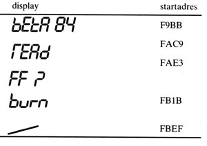
| Beta monitor | F9BF |
| Read EPROM | FAC9 |
| EPROM empty check | FAE3 |
| Write EPROM | FB1B |
| 24 hour clock/alarm | FBEF |
Source and binary of the Beta monitor: Beta Monitor, source, and binary
The Robot Arm
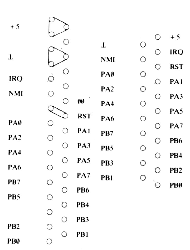
Connectors
Terminal as Temperature controller
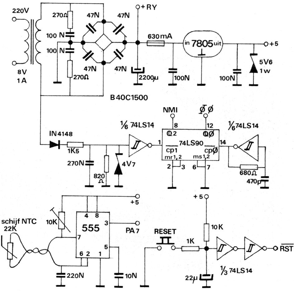
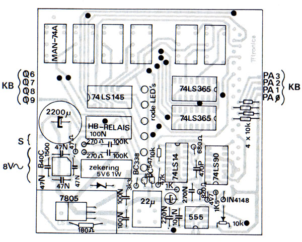
This variant of the terminal shows how the Beta controller can be used to measure temperature and switch a device like a central heating system.
The difference with the development system are no EPROM programmer, a temperature controlled oscillator connected to PA7 and a relay. Also no crystal based clock, and a 50 HZ line frquency based interrupt at the NMI input.
