
AT keyboard interface
Hardware
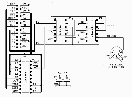
The connector on the top left of the diagram is from my own 6502 boards (see sbc project) and is as it is for two reasons. It’s easy to wire on a stripboard layout and I have a lot of 26 way ribbon, headers and plugs. All the signals are directly from the 6502 except /SEL0 and /SEL1 which are used to select the block $F1xx with /SEL0=1 and /SEL1=0.
The 5 pin DIN socket is shown looking at the holes of the socket. On the finished board I also fitted a PS2 style socket, either one works but the DIN type is easier to mount on stripboard.
The two capacitors are low ESR electrolytics and are placed near the GAL and near the keyboard socket. If you don’t have this type to hand you can use standard electrolytics with some low value ceramic capacitor, say 0.1uF, in parallel.
The GAL16V8A is used purely to generate the read and write strobes. Each is a negative going pulse coincident with phase 2. The interface uses just one byte in the address range. For anyone interested the equations for this chip are in atkey_01.pld and can be compiled with WinCUPL. The fuse file, atkey_01.jed and the compiler listing atkey_01.txt are also included.
The 74LS74 is used to latch the two lowest bits of the data bus during write access to the interface. The reset line is connected so that both of these outputs are cleared at start-up (this disables the keyboard until required).
The outputs from the latches are used to drive the enable pins on two of the four buffers from the 74LS125, these are then used to drive the data and clock lines of the keyboard. The buffers have their inputs tied low so behave like open collector outputs when used like this.
The other two buffers are used to drive the data bus during read access. Note that the keyboard supplies the pull-up for both the data and clock lines so with no keyboard connected you may read zero when you expect a one.
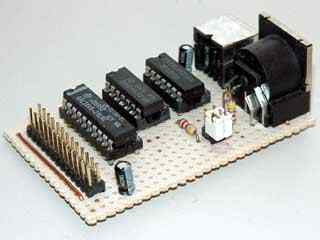
The finished board

Software
The software has a few basic routines to raw handle the keyboard …
ResetAT
This routine sets the pointers to the decode table, clears the lock LEDs and the key status bits for the decode routine. Finally it resets the keyboard.
KeyLEDs
This routine sets the keyboard lock LEDs from the lock LED status byte. Only bits 0, 1 and 2 are used.
ScanAT
This routine scans the keyboard to see if a scancode is waiting. If not it will return with A and RxChar set to zero after about 300uS, otherwise it will return the scancode in A and RxChar.
As well as matrix scancodes possible bytes returned by this routine are …
| $00 | – | No key waiting |
| $AA | – | Power On Self Test Passed (BAT Completed) |
| $EE | – | See Echo Command (Host Commands) |
| $FA | – | Acknowledge |
| $FE | – | Resend |
| $FF | – | Error or Buffer Overflow |
SendAT
This routine is used to send command and control bytes to the keyboard, the codes are ..
| $ED | – | Set the LEDs according to the next byte I send bit 0 = scroll lock bit 1 = num lock bit 2 = caps lock bits 3-7 must be 0, 1 = LED on |
| $EE | – | echo, keyboard will respond with $EE |
| $F0 | – | set scan code set, upon sending the keyboard will respond with ACK ($FA) and then wait for a second byte. sending $01 to $03 determines the code set used, sending $00 will return the code set currently in use. |
| $F3 | – | set typematic repeat rate, upon sending the keyboard will respond with ACK ($FA) and then wait for a second byte. this byte sets the rate. |
| $F4 | – | keyboard enable, clears the keyboard buffer and starts scanning. |
| $F5 | – | keyboard disable, clears the keyboard buffer and stops scanning. |
| $F6 | – | restore default values upon sending the keyboard will respond with ACK ($FA). |
| $FE | – | retransmit the last character please, upon sending the keyboard will respond by resending the last character. |
| $FF | – | reset, you stupid keyboard |
There is one routine to make the keyboard look something like a standard ASCII character device. This is …
ScanKey
This routine checks for a key waiting and if there is will decode it to ASCII and return it in RxChar, else, on return, RxChar will be null. Note some valid key actions will result in a null return such as control, shift and lock keys and any undecoded key(cursor keys for example).
Notes on the decoding table …
Most AT keyboard decoding software uses two tables, one for the unshifted characters and one for the shifted characters, some use further tables for control and alt character decoding as well. In this software The normal and shifted characters are held in the same table but shifted half the table length. This only causes a problem with the numeric pad slash character, /, but this is corrected with a small bit of extra code.
Also some special characters, ¬ and £ (uk keymap), are outside the normal ASCII range.
These are also handled by some extra code. Control characters are handled entirely by code as it is far cheaper, space wise, to do this.
The function keys each generate a unique code but this is not output by the routine, neither is the Win menu key code. It is left to the user how to use these keys. Cursor control keys are not coded as this interface was for a system without a screen type display, but this could easily be changed by adding the desired codes to the decode table.
Lastly the table overlaps the RTS of the last subroutine. This is not a mistake, the first byte in the table is never used so this will save a byte without penalty. For the same reason the table stops two bytes short of the end, again with no real loss.
If space on the target system was really tight then some parts of the code could even be moved into the table, saving about fourteen bytes in total at the cost of a small slow down and increased stack use.
Use of the routines …
To save code, time and space nearly all of the subroutines rely on the values held in two or more registers upon calling and some routines rely on register values and flag states returned. If you are going to change the code read the comments carefully before changing any parts to ensure you don’t violate any of these requirements. The code is fully commented.
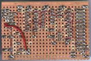
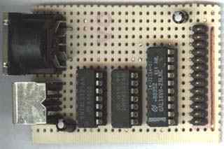
Board close-ups
A final thought
With the addition of two 4k7 resistors this interface would be ideal for use as an i2c bus master, if you look at the finished board photos you can see these resistors and a pair of jumpers to select them. It turns out that another small change needs to be made.
The result can be seen in my I2C project page.
Download here atkey_01.pld
Name     atkey_01 ;
PartNo   00 ;
Date     19/03/01 ;
Revision 01 ;
Designer Lee ;
Company   ;
Assembly None ;
Location  ;
Device   g16v8as ;

/* This GAL is the select logic for the AT keyboard interface board	*/

/* Logic minimisations			None				*/
/* Optimisations			None				*/
/* Download				JEDEC/POF/PRG			*/
/* Doc File Options			fuse plot, equations		*/
/* Output				None				*/

/* *************** INPUT PINS *********************/

PIN	1 = A4		;				/* address bus	*/
PIN	2 = A3		;				/* address bus	*/
PIN	3 = A2		;				/* address bus	*/
PIN	4 = A0		;				/* address bus	*/
PIN	5 = A1		;				/* address bus	*/
PIN	6 = p02		;				/* CPU phase 2	*/
PIN	7 = RW		;				/* read write	*/
PIN	8 = !SEL1	;				/* block select	*/
PIN	9 = !SEL0	;				/* block select	*/
PIN	11 = A6		;				/* address bus	*/
PIN	12 = A5		;				/* address bus	*/
PIN	13 = A7		;				/* address bus	*/

/* *************** OUTPUT PINS *********************/

PIN  19 = !KBR		;			/* key port read strobe		*/
PIN  18 = !KBW		;			/* key port write strobe	*/
/*PIN  17 = 		;			/* 				*/
/*PIN  16 = 		;			/* 				*/
/*PIN  15 = 		;			/* 				*/
/*PIN  14 = 		;			/* 				*/

/* intermediate terms */

ADDR		= !A7 & !A6 & A5 & !A4 & !A3 & !A2 & !A1 & !A0 & !SEL0 & SEL1 ;
							/* F120h (0010 0000)

/* Output terms */

KBR	= ADDR &  RW & p02 ;			/* key port read strobe		*/
KBW	= ADDR & !RW & p02 ;			/* key port write strobe	*/
CUPL(WM)        4.7b  Serial# XX-xxxxxxxx
Device          g16v8as  Library DLIB-h-36-2
Created         Wed Mar 14 21:00:56 2001
Name            ATkey_01
Partno          00
Revision        01
Date            01/08/00
Designer        Lee
Company         P1R8
Assembly        None
Location
*QP20
*QF2194
*G0
*F0
*L00000 10101011101110110111011010010110
*L00256 10101011101110110111101010010110
*L02048 00000000001100000011000000100000
*L02112 00000000001111111111111111111111
*L02144 11111111111111111111111111111111
*L02176 111111111111111110
*C0E13
*7A09
*******************************************************************************
                                   ATkey_01
*******************************************************************************

CUPL(WM)        4.7b Serial# XX-xxxxxxxx
Device          g16v8as  Library DLIB-h-36-2
Created         Wed Mar 14 21:00:56 2001
Name            ATkey_01
Partno          00
Revision        01
Date            01/08/00
Designer        Lee
Company
Assembly        None
Location

===============================================================================
                            Expanded Product Terms
===============================================================================

ADDR =>
    !A0 & !A1 & !A2 & !A3 & !A4 & A5 & !A6 & !A7 & !SEL0 & SEL1

KBR =>
    !A0 & !A1 & !A2 & !A3 & !A4 & A5 & !A6 & !A7 & RW & !SEL0 & SEL1 & p02

KBW =>
    !A0 & !A1 & !A2 & !A3 & !A4 & A5 & !A6 & !A7 & !RW & !SEL0 & SEL1 & p02


===============================================================================
                                 Symbol Table
===============================================================================

Pin Variable                                    Pterms   Max     Min
Pol   Name              Ext     Pin     Type     Used   Pterms  Level
--- --------            ---     ---     ----    ------  ------  -----

    A0                          4        V        -       -       -
    A1                          5        V        -       -       -
    A2                          3        V        -       -       -
    A3                          2        V        -       -       -
    A4                          1        V        -       -       -
    A5                          12       V        -       -       -
    A6                          11       V        -       -       -
    A7                          13       V        -       -       -
    ADDR                        0        I        1       -       -
 !  KBR                         19       V        1       8       1
 !  KBW                         18       V        1       8       1
    RW                          7        V        -       -       -
 !  SEL0                        9        V        -       -       -
 !  SEL1                        8        V        -       -       -
    p02                         6        V        -       -       -


LEGEND    D : default variable         F : field      G : group
          I : intermediate variable    N : node       M : extended node
          U : undefined                V : variable   X : extended variable
          T : function


===============================================================================
                                   Fuse Plot
===============================================================================

Syn   02192 - Ac0   02193 x

Pin #19  02048  Pol x  02120  Ac1 x
 00000 -x-x-x---x---x--x---x--x-xx-x--x
 00032 xxxxxxxxxxxxxxxxxxxxxxxxxxxxxxxx
 00064 xxxxxxxxxxxxxxxxxxxxxxxxxxxxxxxx
 00096 xxxxxxxxxxxxxxxxxxxxxxxxxxxxxxxx
 00128 xxxxxxxxxxxxxxxxxxxxxxxxxxxxxxxx
 00160 xxxxxxxxxxxxxxxxxxxxxxxxxxxxxxxx
 00192 xxxxxxxxxxxxxxxxxxxxxxxxxxxxxxxx
 00224 xxxxxxxxxxxxxxxxxxxxxxxxxxxxxxxx
Pin #18  02049  Pol x  02121  Ac1 x
 00256 -x-x-x---x---x--x----x-x-xx-x--x
 00288 xxxxxxxxxxxxxxxxxxxxxxxxxxxxxxxx
 00320 xxxxxxxxxxxxxxxxxxxxxxxxxxxxxxxx
 00352 xxxxxxxxxxxxxxxxxxxxxxxxxxxxxxxx
 00384 xxxxxxxxxxxxxxxxxxxxxxxxxxxxxxxx
 00416 xxxxxxxxxxxxxxxxxxxxxxxxxxxxxxxx
 00448 xxxxxxxxxxxxxxxxxxxxxxxxxxxxxxxx
 00480 xxxxxxxxxxxxxxxxxxxxxxxxxxxxxxxx
Pin #17  02050  Pol x  02122  Ac1 -
 00512 xxxxxxxxxxxxxxxxxxxxxxxxxxxxxxxx
 00544 xxxxxxxxxxxxxxxxxxxxxxxxxxxxxxxx
 00576 xxxxxxxxxxxxxxxxxxxxxxxxxxxxxxxx
 00608 xxxxxxxxxxxxxxxxxxxxxxxxxxxxxxxx
 00640 xxxxxxxxxxxxxxxxxxxxxxxxxxxxxxxx
 00672 xxxxxxxxxxxxxxxxxxxxxxxxxxxxxxxx
 00704 xxxxxxxxxxxxxxxxxxxxxxxxxxxxxxxx
 00736 xxxxxxxxxxxxxxxxxxxxxxxxxxxxxxxx
Pin #16  02051  Pol x  02123  Ac1 -
 00768 xxxxxxxxxxxxxxxxxxxxxxxxxxxxxxxx
 00800 xxxxxxxxxxxxxxxxxxxxxxxxxxxxxxxx
 00832 xxxxxxxxxxxxxxxxxxxxxxxxxxxxxxxx
 00864 xxxxxxxxxxxxxxxxxxxxxxxxxxxxxxxx
 00896 xxxxxxxxxxxxxxxxxxxxxxxxxxxxxxxx
 00928 xxxxxxxxxxxxxxxxxxxxxxxxxxxxxxxx
 00960 xxxxxxxxxxxxxxxxxxxxxxxxxxxxxxxx
 00992 xxxxxxxxxxxxxxxxxxxxxxxxxxxxxxxx
Pin #15  02052  Pol x  02124  Ac1 -
 01024 xxxxxxxxxxxxxxxxxxxxxxxxxxxxxxxx
 01056 xxxxxxxxxxxxxxxxxxxxxxxxxxxxxxxx
 01088 xxxxxxxxxxxxxxxxxxxxxxxxxxxxxxxx
 01120 xxxxxxxxxxxxxxxxxxxxxxxxxxxxxxxx
 01152 xxxxxxxxxxxxxxxxxxxxxxxxxxxxxxxx
 01184 xxxxxxxxxxxxxxxxxxxxxxxxxxxxxxxx
 01216 xxxxxxxxxxxxxxxxxxxxxxxxxxxxxxxx
 01248 xxxxxxxxxxxxxxxxxxxxxxxxxxxxxxxx
Pin #14  02053  Pol x  02125  Ac1 -
 01280 xxxxxxxxxxxxxxxxxxxxxxxxxxxxxxxx
 01312 xxxxxxxxxxxxxxxxxxxxxxxxxxxxxxxx
 01344 xxxxxxxxxxxxxxxxxxxxxxxxxxxxxxxx
 01376 xxxxxxxxxxxxxxxxxxxxxxxxxxxxxxxx
 01408 xxxxxxxxxxxxxxxxxxxxxxxxxxxxxxxx
 01440 xxxxxxxxxxxxxxxxxxxxxxxxxxxxxxxx
 01472 xxxxxxxxxxxxxxxxxxxxxxxxxxxxxxxx
 01504 xxxxxxxxxxxxxxxxxxxxxxxxxxxxxxxx
Pin #13  02054  Pol x  02126  Ac1 -
 01536 xxxxxxxxxxxxxxxxxxxxxxxxxxxxxxxx
 01568 xxxxxxxxxxxxxxxxxxxxxxxxxxxxxxxx
 01600 xxxxxxxxxxxxxxxxxxxxxxxxxxxxxxxx
 01632 xxxxxxxxxxxxxxxxxxxxxxxxxxxxxxxx
 01664 xxxxxxxxxxxxxxxxxxxxxxxxxxxxxxxx
 01696 xxxxxxxxxxxxxxxxxxxxxxxxxxxxxxxx
 01728 xxxxxxxxxxxxxxxxxxxxxxxxxxxxxxxx
 01760 xxxxxxxxxxxxxxxxxxxxxxxxxxxxxxxx
Pin #12  02055  Pol x  02127  Ac1 -
 01792 xxxxxxxxxxxxxxxxxxxxxxxxxxxxxxxx
 01824 xxxxxxxxxxxxxxxxxxxxxxxxxxxxxxxx
 01856 xxxxxxxxxxxxxxxxxxxxxxxxxxxxxxxx
 01888 xxxxxxxxxxxxxxxxxxxxxxxxxxxxxxxx
 01920 xxxxxxxxxxxxxxxxxxxxxxxxxxxxxxxx
 01952 xxxxxxxxxxxxxxxxxxxxxxxxxxxxxxxx
 01984 xxxxxxxxxxxxxxxxxxxxxxxxxxxxxxxx
 02016 xxxxxxxxxxxxxxxxxxxxxxxxxxxxxxxx


LEGEND    X : fuse not blown
          - : fuse blown


===============================================================================
                                 Chip Diagram
===============================================================================

                               ______________
                              |   ATkey_01   |
                       A4 x---|1           20|---x Vcc
                       A3 x---|2           19|---x !KBR
                       A2 x---|3           18|---x !KBW
                       A0 x---|4           17|---x
                       A1 x---|5           16|---x
                      p02 x---|6           15|---x
                       RW x---|7           14|---x
                    !SEL1 x---|8           13|---x A7
                    !SEL0 x---|9           12|---x A5
                      GND x---|10          11|---x A6
                              |______________|
; IBM AT keyboard interface for 6502 L.Davison, 2001
; port address is set by your hardware configuration
; page zero bytes used = 8
; code bytes (including tables) less than 690
; works with 102 key standard and 105 key Win95/98 keyboards

; The main, externally useable routines are ...

; ResetAT		resets the keyboard, flags & LEDs
; KeyLEDs		sets the keyboard LEDs
; GetAT			scans the keyboard and waits for a key
; ScanAT		scans the keyboard, returns after timeout if no key
; Send_AT		sends a byte to the keyboard
; GetKey		scans & decodes the keyboard, waits for a key but may still
;			return null for some keys.
; ScanKey		scans & decodes the keyboard, returns after a timeout if no key

; addresses used ...

KPort		=	$F120	; keyboard port, o.c. outputs, tristate inputs
				; bit 0 is data
				; bit 1 is clock
				; bits 2 to 7 are unused
KTable		=	$F1	; (and $F2) keyboard table pointer
TxChar		=	$F3	; transmit character buffer
RxChar		=	$F4	; receive character buffer
RxParity	=	$F5	; receive character parity buffer (Bit 0 only)
LEDBits		=	$F6	; LED status bits
				; bit 0 = scroll lock,	1 = LED on
				; bit 1 = num lock,	1 = LED on
				; bit 2 = caps lock,	1 = LED on
				; bits 3 to 7 are unused but may get trashed
KeyBits		=	$F7	; key status bits
				; bit 0 = Lshift,	1 = key down
				; bit 1 = Lcontrol,	1 = key down
				; bit 2 = Lwin,		1 = key down
				; bit 3 = Lalt,		1 = key down
				; bit 4 = Rshift,	1 = key down
				; bit 5 = Rcontrol,	1 = key down
				; bit 6 = Rwin,		1 = key down
				; bit 7 = Ralt,		1 = key down
RxTwo		=	$F8	; key two code flag and temporary counter

		*=	$2000	; set origin (put this where you like. ROM or RAM)

; keyboard decoding routine. the entry point is ScanKey for a non
; halting keyboard poll. if there is a key waiting it will be
; returned in RxChar, else, on return, RxChar will be null.

				; key pressed was break [pause] key
WasBRK
	LDA	#$07		; seven more scancodes to ignore
				; ($14,$77,$E1,$F0,$14,$F0,$77)
	STA	RxTwo		; copy code count
Ploop
	JSR	GetAT		; get scancode
	DEC	RxTwo		; decrement count
	BNE	Ploop		; loop if not all pause bytes done

	LDA	#$03		; make break = [CTRL-C]
	STA	RxChar		; save key
	RTS

				; process lifted key
KeyUp
	JSR	GetAT		; get lifted key scancode
	ORA	RxTwo		; OR in table half
	TAY			; set index from scancode
	LDA	(KTable),Y	; get keycode
	TAX			; save key for now
	AND	#$F0		; mask top nibble
;	CMP	#$C0		; function key ?
;	BEQ	FuncKeyUP	; was function key, use this branch for you own
;				; function key up handler (X holds char code)

	CMP	#$90		; bit hold ?
	BNE	ScanKey		; not bit hold, go get next
				; ignores other key releases

	LDA	#$00		; clear A

				; was bit hold key (for up OR down key)
BitHold
	STA	RxTwo		; save key up/down flag ($90 for down, $00 for up)
	TXA			; get key back
	CMP	#$98		; compare with win_menu key
	BCS	ScanKey		; ignore $98 - $9F

				; if here key is either, [L_SHIFT], [L_CTRL],
				; [L_WIN], [L_ALT], [R_SHIFT], [RCTRL], [R_WIN]
				; or [R_ALT]

				; rotates a 1 into a byte of 0s to
				; toggle the pressed/lifted key's bit
	AND	#$07		; mask lower 3 bits
	TAX			; key # to X
	LDA	#$00		; clear A
	SEC			; set -1 bit
R_Loop
	ROL	A		; rotate zero bit through A
	DEX			; decrement bit count
	BPL	R_Loop		; loop if not that key

	LDX	RxTwo		; get key up flag
	BEQ	ClearBit	; branch if was it key up

	ORA	KeyBits		; set the bit
	BNE	SavBits		; branch always (always at least one bit set)

ClearBit
	EOR	#$FF		; make only one bit = 0
	AND	KeyBits		; clear the bit
SavBits
	STA	KeyBits		; and save it back

	BCC	ScanKey		; go get next scancode (branch always)

				; handle num, caps and scroll lock keys
SetUnset
	TXA			; get key back
	EOR	LEDBits		; toggle the LED bits
	STA	LEDBits		; save new LED bits
	JSR	KeyLEDs		; set the keyboard LEDs

; get a key from the keyboard, exits with null after timeout
; This is the main entry point for this routine

ScanKey
	JSR	ScanAT		; scan keyboard
	BNE	ProcKey		; if key go do next

	RTS

; get a key from the keyboard, waits for a valid key
; This is the secondary entry point for this routine

GetKey
	JSR	GetAT		; get key scancode
ProcKey
	CMP	#$E1		; is it pause (break)
	BEQ	WasBRK		; branch if so

	CMP	#$AA		; is it selftest pass
	BEQ	ScanKey		; branch if was

	CMP	#$FF		; is it error or buffer overflow
	BNE	NotOF		; branch if not

	JSR	ClearOF		; clear overflow
	BNE	ScanKey		; get scancode again (branch always)

				; when here we have handled startup, errors and [BREAK]
NotOF
	CMP	#$E0		; is it $E0 (two byte sequence)
	BNE	NotE0		; branch if not

	JSR	GetAT		; get second scancode
	LDX	#$80		; set for double key code
NotE0
	STX	RxTwo		; set/clear two code flag
	CMP	#$F0		; is it $F0 (key up)
	BEQ	KeyUp		; branch if up

				; key has been pressed
	ORA	RxTwo		; OR in table half
	TAY			; set index from scancode
	LDA	(KTable),Y	; get keycode
	TAX			; save key for now
	AND	#$F0		; mask top nibble
	CMP	#$80		; bit set/unset ?
	BEQ	SetUnset	; was bit set/unset

	CMP	#$90		; bit hold ?
	BEQ	BitHold		; was so go set hold bit

	CMP	#$C0		; function key ?
;	BEQ	FuncKey		; was function key, use this branch for you own
				; function key down handler (X holds char code)
	BEQ	ScanKey		; was function key, ignore for now

				; key is not function, bit change or lock key
	LDA	LEDBits		; get the LED bits
	AND	#$04		; check CAPS lock
	BEQ	NotCapsL			; skip CAPS if not set

	TXA			; get key back
	CMP	#("a"+$80)	; compare with "a" (shiftable)
	BCC	NotCapsL	; branch if less

	CMP	#("z"+$80+1)	; compare with "z"+1 (shiftable)
	BCS	NotCapsL	; branch if >=

				; caps lock on and was alpha, so shift it
	TYA			; copy index
	EOR	#$80		; do CAPS LOCK
	TAY			; back to index

NotCapsL
	TYA			; copy scancode
	CMP	#$CA		; compare with keypad "/"
	BEQ	Shift		; correct keypad "/"

	CMP	#$69		; compare scancode with lowest numeric pad code
	BCC	NotNumpad	; branch if < CMP #$7E ; compare scancode with highest numeric pad code+1 BCS NotNumpad ; branch if >= (not numeric)

				; gets here if numeric pad code
	LDA	LEDBits		; get the LED bits
	AND	#$02		; check NUM lock
	BNE	NoShift		; skip NUM if set (works backwards! like it should)

	TXA			; get key back
	BMI	Shift		; branch if was numeric (shiftable)

				; key wasn't numeric so now check shift keys status'
NotNumpad
	LDA	KeyBits		; get held bit flags
	AND	#$11		; mask shift bits
	BEQ	NoShift		; there was no shift applied

				; if here then either shift was held (or both)
	TXA			; get key back
	BPL	NoShift		; branch if not shiftable

Shift
	TYA			; copy index
	EOR	#$80		; do the shift (or NUM LOCK)
	TAY			; copy to index
NoShift
	LDA	(KTable),Y	; get keycode
	CPY	#$80		; check scancode
	BCS	FixPound	; skip if from second half of table (¬ and £)

	AND	#$7F		; clear shiftable bit (lower half of table only)
FixPound
	TAX			; save key for now

	LDA	KeyBits		; get held bit flags
	AND	#$22		; mask control bits
	BEQ	NoCtrl		; was no control key applied

	TXA			; get key back (again)
	CMP	#$40		; compare with "@"
	BCC	NoCtrl		; branch if <, not in range CMP #$80 ; compare with [DEL]+1 BCS NoCtrl ; branch if >=, not in range

				; [CTRL] key held and in range, mask it
	AND	#$1F		; convert to control key
	TAX			; copy key to X
NoCtrl
	STX	RxChar		; save key
	RTS

; scan the keyboard to see if a key is waiting. returns scancode in A
; and RxChar, or $00 if no key waiting. this is the main entry point.

; if the keyboard response seems flakey when holding a key for auto
; repeat then increase the timeout, it helps. This was the shortest
; I could reliably get away with with all the test keyboards.

; possible bytes (apart from scancodes) are ...

; $AA		Power On Self Test Passed (BAT Completed)
; $EE		See Echo Command (Host Commands)
; $FA		Acknowledge
; $FE		Resend
; $FF		Error or Buffer Overflow

; when exiting this routine the clock is pulled low to hold off transmission.
; the X register is assumed to be $00 on exit and that the Z flag reflects
; the byte in A.

ScanAT
;	LDX	#$0D		; set timeout count (150uS, 1MHz 6502)
	LDX	#$1A		; set timeout count (150uS, 2MHz 6502)

	LDA	#$03		; clock high, data high
	STA	KPort		; out to clock port (allow to send)
	LDA	#$02		; set for clock line bit test
WaitW0
	BIT	KPort		; test the clock line
	BEQ	WaitW1		; go do rest if the clock falls

	DEX			; else decrement timeout value
	BNE	WaitW0		; go wait some more if time is not up yet

	LDA	#$01		; else stop keyboard
	STA	KPort		; out to port (prevent sending)
	TXA			; copy $00 to A
	STA	RxChar		; save in buffer (no character)
	RTS			;

				; Rx error, try again
RxWasNOK
	LDA	#$FE		; resend command
	JSR	SendAT		; send A to keyboard

; scan the keyboard and wait for a key. returns scancode in A and RxChar.
; this is the secondary entry point.

GetAT
	LDA	#$03		; clock high, data high
	STA	KPort		; out to clock port (allow to send)
	LDA	#$02		; set for clock line bit test
WaitW1
	JSR	GetBit		; get bit from keyboard (start bit)
	LDX	#$08		; eight data bits to get
	LDY	#$01		; 1's count to one (odd parity)
RecByte
	JSR	GetBit		; get bit from keyboard (data bit)
	BCC	NoRx1		; brabch if bit was zero

	INY			; else increment 1's count
NoRx1
	ROR	RxChar		; bit into receive byte
	DEX			; decrement bit count
	BNE	RecByte		; loop if more data

	JSR	GetBit		; get bit from keyboard (parity bit)
	ROL	RxParity	; bit into parity byte b0
	JSR	GetBit		; get bit from keyboard (stop bit)
	LDA	#$01		; drive clock low (hold off more data)
	STA	KPort		; out to port

	TYA			; get computed parity
	EOR	RxParity	; compare with received parity bit
	ROR	A		; only interested in bit 0
	BCS	RxWasNOK	; go try again if not ok
				; (rx parity <> computed parity)

	LDA	RxChar		; else copy scancode
	BEQ	ClearOF		; branch if was error or buffer overflow

	RTS

; gets a bit from the keyboard, bit to send is in Cb
; take care to enter this routine with A = $02

GetBit
	BIT	KPort		; test the clock line
	BNE	GetBit		; wait for the clock to fall

	LDA	KPort		; get data
	LSR	A		; data bit to Cb
	LDA	#$02		; set for clock line bit test
WaitR1
	BIT	KPort		; test the clock line
	BEQ	WaitR1		; wait for the clock to rise

	RTS			;

; sets the pointers to the decode table, resets the keyboard and sets the
; lock LEDs. also clears the status bits for the decoder.

ResetAT
	LDA	#<ATtable ; point to ATtable (low addr) STA KTable ; save pointer low byte LDA #>ATtable	; point to ATtable (high addr)
	STA	KTable+1	; save pointer high byte
	LDA	#$00		; clear bits
	STA	KeyBits		; clear hold bits
	STA	LEDBits		; clear LED bits
	LDA	#$FF		; reset the keyboard
	JSR	SendAT		; send A to keyboard
	LDA	#$F6		; restore default settings
	JSR	SendAT		; send A to keyboard
	JSR	KeyLEDs		; set keyboard LEDs
ClearOF
	LDA	#$F4		; clear the buffer
	BNE	SendAT		; send A to keyboard & return (branch always)

; set the keyboard LEDs from LEDBits

KeyLEDs
	LDA	#$ED		; next byte is LED bits
	JSR	SendAT		; send A to keyboard
	LDA	LEDBits		; get LED bits
	AND	#$07		; make sure bits 3 to 7 = 0

; SendAT sends the special codes to the keyboard, codes are ..

; $ED		set the LEDs according to the next byte I send
;		bit 0 = scroll lock
;		bit 1 = num lock
;		bit 2 = caps lock
;		bits 3-7 must be 0, 1 = LED on
; $EE		echo, keyboard will respond with $EE
; $F0		set scan code set, upon sending the keyboard will
;		respond with ACK ($FA) and then wait for a second
;		byte. sending $01 to $03 determines the code set
;		used, sending $00 will return the code set currently
;		in use.
; $F3		set typematic repeat rate, upon sending the keyboard
;		will respond with ACK ($FA) and then wait for a second
;		byte. this byte sets the rate.
; $F4		keyboard enable, clears the keyboard buffer and starts
;		scanning.
; $F5		keyboard disable, clears the keyboard buffer and stops
;		scanning.
; $F6		restore default values upon sending the keyboard will
;		respond with ACK ($FA)
; $FE		retransmit the last character please upon sending the
;		keyboard will respond by resending the last character
; $FF		reset, you stupid keyboard

SendAT
	STA	TxChar		; save A in transmit buffer
Send_AT
	LDX	#$08		; eight bits to send
	LDY	#$01		; 1's count to one (odd parity)
	LDA	#$02		; clock high, data low
	STA	KPort		; out to clock port (tell keyboard to receive)
SendByte
	ROR	TxChar		; bit into carry
	BCC	NotOne		; skip increment if zero

	INY			; else increment 1's count
NotOne
	JSR	SendBit		; send bit to keyboard
	DEX			; decrement bit count
	BNE	SendByte	; loop if not all done

	ROR	TxChar		; last bit back into TxChar
	TYA			; copy parity count
	LSR	A		; parity bit into carry
	LDA	#$02		; set for clock line bit test
	JSR	SendBit		; send bit to keyboard
	SEC			; set stop bit
	JSR	SendBit		; send bit to keyboard
	JSR	SendBit		; send bit to keyboard (skips extra clock after bit 10)

;	LDX	#$04		; 20uS delay (1Mhz 6502)
	LDX	#$08		; 20uS delay (2Mhz 6502)
Wait20
	DEX			; decrement count
	BNE	Wait20		; loop for a while

	LDA	#$01		; drive clock low (handshake)
	STA	KPort		; out to port

;	LDX	#$09		; 44uS delay (1Mhz 6502)
	LDX	#$12		; 44uS delay (2Mhz 6502)
Wait44
	DEX			; decrement count
	BNE	Wait44		; loop for a while

	JSR	GetAT		; get the response
	CMP	#$FE		; compare with not ok response
	BEQ	Send_AT		; if wrong go do it again

	RTS			;

; send bit to keyboard, Cb is the bit to send
; take care to enter this routine with A = $02

SendBit
	BIT	KPort		; test the clock line
	BNE	SendBit		; wait for the clock to fall

	LDA	#$01		; unshifted bit for clock
	ROL	A		; shift Cb into A
	STA	KPort		; out to clock port
	ROR	A		; shift bit back to Cb
	LDA	#$02		; set for clock line bit test
WaitT1
	BIT	KPort		; test the clock line
	BEQ	WaitT1		; wait for the clock to rise

ATtable				; the first byte of the table is unused so
	RTS			; this RTS can be the first byte

; AT keyboard decoding table

; [Fn] keys are coded $C1 to $CC but not acted on

; Lock keys are ..
;	[SCROLL LOCK]		$81
;	[NUM LOCK]		$82
;	[CAPS LOCK]		$84
; ... and they change flags internal to the decode routine,
; they also toggle the keyboard LEDs

; other non character keys are ..
;	[L_SHIFT]		$90
;	[L_CTRL]		$91
;	[L_WIN]			$92 (toggles bit but otherwise ignored)
;	[L_ALT]			$93 (toggles bit but otherwise ignored)
;	[R_SHIFT]		$94
;	[R_CTRL]		$95
;	[R_WIN]			$96 (toggles bit but otherwise ignored)
;	[R_ALT]			$97 (toggles bit but otherwise ignored)
;	[WIN_MENU]		$98 (ignored)

; AT keyboard decoding table first part.
; this mostly holds unshifted key values
; the second character in the comments field is usually the shifted
; character for that key

;ATtable
;	.byte	$00		; first byte replaced by RTS above
	.byte	$C9		; [F9]
	.byte	$00  		;
	.byte	$C5		; [F5]
	.byte	$C3		; [F3]
	.byte	$C1		; [F1]
	.byte	$C2		; [F2]
	.byte	$CC		; [F12]
	.byte	$00		;
	.byte	$CA		; [F10]
	.byte	$C8		; [F8]
	.byte	$C6		; [F6]
	.byte	$C4		; [F4]
	.byte	$09		; [TAB]
	.byte	("`"+$80)	; `	¬
	.byte	$00		;

	.byte	$00		;
	.byte	$93		; [L_ALT]
	.byte	$90		; [L_SHIFT]
	.byte	$00		;
	.byte	$91		; [L_CTRL]
	.byte	("q"+$80)	; q	Q
	.byte	("1"+$80)	; 1	!
	.byte	$00		;
	.byte	$00		;
	.byte	$00		;
	.byte	("z"+$80)	; z	Z
	.byte	("s"+$80)	; s	S
	.byte	("a"+$80)	; a	A
	.byte	("w"+$80)	; w	W
	.byte	("2"+$80)	; 2	"
	.byte	$00		;

	.byte	$00		;
	.byte	("c"+$80)	; c	C
	.byte	("x"+$80)	; x	X
	.byte	("d"+$80)	; d	D
	.byte	("e"+$80)	; e	E
	.byte	("4"+$80)	; 4	$
	.byte	("3"+$80)	; 3	£
	.byte	$00		;
	.byte	$00		;
	.byte	" "		; [SPACE]
	.byte	("v"+$80)	; v	V
	.byte	("f"+$80)	; f	F
	.byte	("t"+$80)	; t	T
	.byte	("r"+$80)	; r	R
	.byte	("5"+$80)	; 5	%
	.byte	$00		;

	.byte	$00		;
	.byte	("n"+$80)	; n	N
	.byte	("b"+$80)	; b	B
	.byte	("h"+$80)	; h	H
	.byte	("g"+$80)	; g	G
	.byte	("y"+$80)	; y	Y
	.byte	("6"+$80)	; 6	^
	.byte	$00		;
	.byte	$00		;
	.byte	$00		;
	.byte	("m"+$80)	; m	M
	.byte	("j"+$80)	; j	J
	.byte	("u"+$80)	; u	U
	.byte	("7"+$80)	; 7	&
	.byte	("8"+$80)	; 8	*
	.byte	$00		;

	.byte	$00		;
	.byte	(","+$80)	; ,	< .byte ("k"+$80) ; k K .byte ("i"+$80) ; i I .byte ("o"+$80) ; o O .byte ("0"+$80) ; 0 ) .byte ("9"+$80) ; 9 ( .byte $00 ; .byte $00 ; .byte ("."+$80) ; . >
	.byte	($2F+$80)	; /	?
	.byte	("l"+$80)	; l	L
	.byte	(";"+$80)	; ;	:
	.byte	("p"+$80)	; p	P
	.byte	("-"+$80)	; -	_
	.byte	$00		;

	.byte	$00		;
	.byte	$00		;
	.byte	($27+$80)	; '	@
	.byte	$00		;
	.byte	("["+$80)	; [	{
	.byte	("="+$80)	; =	+
	.byte	$00		;
	.byte	$00		;
	.byte	$84		; [CAPS LOCK]
	.byte	$94		; [R_SHIFT]
	.byte	$0D		; [RETURN]
	.byte	("]"+$80)	; ]	}
	.byte	$00		;
	.byte	("#"+$80)	; #	~
	.byte	$00		;
	.byte	$00		;

; keys with bit 7 set, but not the /, are only affected by num lock
; these are the num lock on values

	.byte	$00		;
	.byte	("\"+$80)	; \	|
	.byte	$00		;
	.byte	$00		;
	.byte	$00		;
	.byte	$00		;
	.byte	$08		; [BACKSPACE]
	.byte	$00		;
	.byte	$00		;
	.byte	("1"+$80)	; 1 keypad
	.byte	$00		;
	.byte	("4"+$80)	; 4 keypad
	.byte	("7"+$80)	; 7 keypad
	.byte	$00		;
	.byte	$00		;
	.byte	$00		;

	.byte	("0"+$80)	; 0 keypad
	.byte	("."+$80)	; . keypad
	.byte	("2"+$80)	; 2 keypad
	.byte	("5"+$80)	; 5 keypad
	.byte	("6"+$80)	; 6 keypad
	.byte	("8"+$80)	; 8 keypad
	.byte	$1B		; [ESC]
	.byte	$82		; [NUM LOCK]
	.byte	$CB		; [F11]
	.byte	"+"		; + keypad
	.byte	("3"+$80)	; 3 keypad
	.byte	"-"		; - keypad
	.byte	"*"		; * keypad
	.byte	("9"+$80)	; 9 keypad
	.byte	$81		; [SCROLL LOCK]
	.byte	$00		;


; AT keyboard decoding table second part.
; this mostly holds shifted key values of the first half

	.byte	$00		;
	.byte	$00		;
	.byte	$00		;
	.byte	$C7		; [F7]
	.byte	$00		;
	.byte	$00		;
	.byte	$00		;
	.byte	$00		;
	.byte	$00		;
	.byte	$00		;
	.byte	$00		;
	.byte	$00		;
	.byte	$00		;
	.byte	$00		;
	.byte	"¬"		; [SHIFT] `
	.byte	$00		;

	.byte	$00		;
	.byte	$97		; [R_ALT]
	.byte	$00		;
	.byte	$00		;
	.byte	$95		; [R_CTRL]
	.byte	"Q"		; [SHIFT] q
	.byte	"!"		; [SHIFT] 1
	.byte	$00		;
	.byte	$00		;
	.byte	$00		;
	.byte	"Z"		; [SHIFT] z
	.byte	"S"		; [SHIFT] s
	.byte	"A"		; [SHIFT] a
	.byte	"W"		; [SHIFT] w
	.byte	$22		; [SHIFT] 2
	.byte	$92		; [L_WIN]

	.byte	$00		;
	.byte	"C"		; [SHIFT] c
	.byte	"X"		; [SHIFT] x
	.byte	"D"		; [SHIFT] d
	.byte	"E"		; [SHIFT] e
	.byte	"$"		; [SHIFT] 4
	.byte	"£"		; [SHIFT] 3
	.byte	$96		; [R_WIN]
	.byte	$00		;
	.byte	$00		;
	.byte	"V"		; [SHIFT] v
	.byte	"F"		; [SHIFT] f
	.byte	"T"		; [SHIFT] t
	.byte	"R"		; [SHIFT] r
	.byte	"%"		; [SHIFT] 5
	.byte	$98		; [WIN_MENU]

	.byte	$00		;
	.byte	"N"		; [SHIFT] n
	.byte	"B"		; [SHIFT] b
	.byte	"H"		; [SHIFT] h
	.byte	"G"		; [SHIFT] g
	.byte	"Y"		; [SHIFT] y
	.byte	"^"		; [SHIFT] 6
	.byte	$00		;
	.byte	$00		;
	.byte	$00		;
	.byte	"M"		; [SHIFT] m
	.byte	"J"		; [SHIFT] j
	.byte	"U"		; [SHIFT] u
	.byte	"&"		; [SHIFT] 7
	.byte	"*"		; [SHIFT] 8
	.byte	$00		;

	.byte	$00		;
	.byte	"<" ; [SHIFT] , .byte "K" ; [SHIFT] k .byte "I" ; [SHIFT] i .byte "O" ; [SHIFT] o .byte ")" ; [SHIFT] 0 .byte "(" ; [SHIFT] 9 .byte $00 ; .byte $00 ; .byte ">"		; [SHIFT] .
	.byte	$3F		; / keypad
	.byte	"L"		; [SHIFT] l
	.byte	":"		; [SHIFT] ;
	.byte	"P"		; [SHIFT] p
	.byte	"_"		; [SHIFT] -
	.byte	$00		;

	.byte	$00		;
	.byte	$00		;
	.byte	"@"		; [SHIFT] '
	.byte	$00		;
	.byte	"{"		; [SHIFT] [
	.byte	"+"		; [SHIFT] =
	.byte	$00		;
	.byte	$00		;
	.byte	$00		;
	.byte	$00		;
	.byte	$0D		; [ENTER] keypad
	.byte	"}"		; [SHIFT] ]
	.byte	$00		;
	.byte	"~"		; [SHIFT] #
	.byte	$00		;
	.byte	$00		;

; keys marked "& keypad" are only affected by num lock
; these are the num lock off values

	.byte	$00		;
	.byte	"|"		; [SHIFT] \
	.byte	$00		;
	.byte	$00		;
	.byte	$00		;
	.byte	$00		;
	.byte	$00		;
	.byte	$00		;
	.byte	$00		;
	.byte	$00		; [END]		& keypad
	.byte	$00		;
	.byte	$00		; [CURSOR_LT]	& keypad
	.byte	$00		; [HOME]	& keypad
	.byte	$00		;
	.byte	$00		;
	.byte	$00		;

	.byte	$00		; [INSERT]
	.byte	$7F		; [DELETE]	& keypad
	.byte	$00		; [CURSOR_DN]	& keypad
	.byte	$00		;
	.byte	$00		; [CURSOR_RT]	& keypad
	.byte	$00		; [CURSOR_UP]	& keypad
	.byte	$00		;
	.byte	$00		;
	.byte	$00		;
	.byte	$00		;
	.byte	$00		; [PAGE_DN]	& keypad
	.byte	$00		;
	.byte	$00		;
	.byte	$00		; [PAGE_UP]	& keypad
;	.byte	$00		; these two bytes are never accessed so don't
;	.byte	$00		; need to be defined in the table

	END