
IDE bus interface circuit
Hardware
IDE Bus interface circuit.
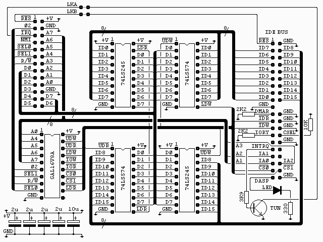
The connector on the top left of the diagram is from my own 6502 boards (see the sbc project) and is as it is for two reasons. It’s easy
to wire on a stripboard layout and I have a lot of 26 way ribbon, headers and plugs. All the signals are directly from the 6502 except /SEL0 and /SEL1 which are used to select the block $F1xx with /SEL0 = 1 and /SEL1 = 0.
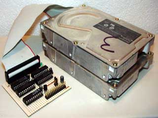
A 40 pin IDC header, re-cycled from a PC motherboard, is used to connect to the IDE bus.
All the capacitors are low ESR electrolytics and are placed one near each chip. If you don’t have this type to hand you can use standard electrolytics with some low value
ceramic capacitor, say 0.1uF, in parallel.
The GAL16V8A is used to generate the read and write strobes for the buffers and latches and to generate the IOR and IOW strobes for the IDE bus. All are active low. The interface uses 32 bytes in the address range as it is a 16 bit port with 16 addresses. For anyone interested the equations for this chip are in ide_01.pld and can be compiled with WinCUPL. The fuse file, ide_01.jed and the compiler listing, ide_01.txt are also included.
| Address | Read | Write | Width |
| $00 | Data | 16 Bit | |
| $02 | Error | Precomp | 8 Bit |
| $04 | Sector count | 8 Bit | |
| $06 | LBA bits 0 to 8 / CHS Sector number | 8 Bit | |
| $08 | LBA bits 8 to 15 / CHS Cylinder low | 8 Bit | |
| $0A | LBA bits 16 to 23 / CHS Cylinder high | 8 Bit | |
| $0C | Drive select & LBA bits 24 to 27 / CHS Head select | 8 Bit | |
| $0E | Status | Command | 8 Bit |
| $1C | Alternate status | Device control | 8 Bit |
| $1E | Drive address | Not used | 8 Bit |
For ATAPI devices some of the register names and functions change. Here is the ATAPI map.
| Address | Read | Write | Width |
| $00 | Data | 16 Bit | |
| $02 | Error | Feature | 8 Bit |
| $04 | Interrupt reason | Not used | 8 Bit |
| $06 | Not used | ||
| $08 | Byte count low | 8 Bit | |
| $0A | Byte count high | 8 Bit | |
| $0C | Device select | 8 Bit | |
| $0E | Status | Command | 8 Bit |
| $1C | Alternate status | Device control | 8 Bit |
| $1E | Not used | ||
All reads and writes to the IDE bus are sixteen bits wide. On write, first the lower eight bits are written to the even address (A0 = 0) and latched by one 74LS574, Then the upper eight bits are written to the corresponding odd address (A0 = 1) and are presented to the upper eight bits of the IDE bus by the 74LS245, a bi-directional buffer used here in the one direction only. These eight bits, along with the previously latched lower
eight bits, make up the sixteen bits needed for a write operation.
On read the lower eight bits are read from the IDE bus even address (A0 = 0) via the second 74LS245 and, as this read takes place the upper, eight bits from the IDE bus are latched by the second 74LS574. The upper eight bits can then be read from the 74LS574 latch.
The interface is arranged thus so that ..
- All 16 bits are used, this allows us to utilise the full capacity of the drive.
- Reads and writes are symmetrical, i.e. both are done low byte and then high byte.
- The status registers on ATA devices are all on the low byte, fast polling is possible because only the low byte needs to be read.
The disadvantage is that every write must be sixteen bits, even if the top eight bits
aren’t used.
Other features are ..
- An activity LED. Illuminates during ATA device activity. If required this could be wired off board.
- A reset jumper. This ties the IDE bus reset to the CPU reset so both are reset together.
- An IRQ jumper. This is to allow an interrupt based driver to be developed.
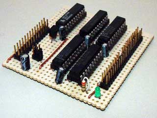
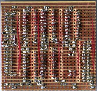
The finished board.
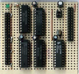
Close-up views.
Software.
At present only a BASIC demonstration program is available. It can be seen here.
Download this file
10 REM set disk interface values
20 REM enhanced BASIC version
30 REM supports ATA but not ATAPI devices
100 AD=$F100 : REM interface base address
110 IO=AD+$00 : REM input/output register - 16 bits
120 ER=AD+$02 : REM error/precomp register
130 SC=AD+$04 : REM sector count
140 SS=AD+$06 : REM LBA bits 0 to 7
150 CL=AD+$08 : REM LBA bits 8 to 15
160 CH=AD+$0A : REM LBA bits 26 to 23
170 HR=AD+$0C : REM drive/LBA bits 24 to 27
180 SR=AD+$0E : REM status/command
190 RR=AD+$0C+$10 : REM alternate status/device control
200 AS=AD+$0E+$10 : REM drive address
210 MD=%10100000 : REM these bits must always be set
220 BK=%01000000 : REM value to set LBA mode
1000 REM set parameters to defaults
1005 DOKE RR,6 : REM write device control
1010 DOKE SC,1 : REM sector count
1020 DOKE SS,0 : REM LBA bits 0 to 7
1030 DOKE CL,0 : REM LBA bits 8 to 15
1040 DOKE CH,0 : REM LBA bits 26 to 23
1050 DOKE HR,MD+BK : REM drive/LBA upper 4 bits
1055 DOKE RR,2 : REM write device control
1060 GOSUB 1300
1065 PRINT : GOSUB 3100
1070 PRINT
1080 PRINT "0  Select drive"
1090 PRINT "1  Reset device"
1100 PRINT "2  Identify device"
1110 PRINT "3  Sleep device"
1120 PRINT "4  Idle device"
1130 PRINT "5  Standby device"
1140 PRINT "6  Query power mode"
1150 PRINT "7  Execute diagnostics"
1160 PRINT "8  Recalibrate"
1170 PRINT "9  Test read"
1175 PRINT "10 Write BASIC""
1180 PRINT
1190 PRINT "Choose one";
1200 INPUT I
1210 I=I+1
1220 IF (I<1) OR (I>11) THEN 1200
1230 PRINT
1240 ON I GOSUB 3000,1300,6000,2200,2300,2400,2500,2600,2900,2700,20000
1250 GOTO 1065
1300 REM reset device(s)
1310 DOKE HR,(MD+BK) EOR 16 : REM select other drive
1320 CMD=8
1330 GOSUB 11020
1340 DOKE HR,MD+BK : REM select drive
1350 CMD=8
1360 GOSUB 11020
1370 RETURN
2200 REM go to sleep
2210 CMD=230
2220 DOKE SR,CMD : REM send command
2230 RETURN
2300 REM go to idle mode
2310 CMD=225
2320 GOTO 11000
2400 REM go to standby mode
2410 CMD=224
2420 GOTO 11000
2500 REM query device power mode
2510 CMD=229
2520 GOSUB 11000
2530 I=DEEK(SC) AND 255 : REM sector count
2540 PRINT "Device is in ";
2550 IF I=0 THEN PRINT "standby"; : GOTO 2590
2560 IF I=128 THEN PRINT "idle"; : GOTO 2590
2570 IF I=255 THEN PRINT "active"; : GOTO 2590
2580 PRINT "unknown";
2590 PRINT " mode"
2595 RETURN
2600 REM execute diagnostics
2610 CMD=144
2620 GOSUB 11000
2630 I=(DEEK(ER) AND 255) : REM read error register
2640 PRINT "Device 0 ";
2650 IF (I AND 127)=1 THEN PRINT "passed" : GOTO 2670
2660 PRINT "failed"
2670 PRINT "Device 1 ";
2680 IF (I AND 128) THEN PRINT "failed" : GOTO 2695
2690 PRINT "passed or not present"
2695 RETURN
2700 REM test read
2710 INPUT "Sector number";IX
2725 GOSUB 10000
2730 CMD=32
2740 GOSUB 11000
2750 REM display sector
2760 S$=""
2770 PRINT
2780 FOR WC=0 TO 255
2790 GOSUB 12000
2800 HH=(HI/256) AND 127
2810 IF HH < 32 THEN HH=46
2815 HL=HI AND 127
2820 IF HL <32 THEN HL=46
2825 S$=S$+CHR$(HL)
2830 S$=S$+CHR$(HH)
2865 PRINT " ";HEX$(HI,4);
2870 IF (WC AND 7)< >7 THEN 2885
2875 PRINT "    ";S$
2880 S$=""
2885 NEXT
2890 RETURN
2900 REM recalibrate device (seek to 0)
2910 IX=0
2920 GOSUB 10000
2930 CMD=16
2940 GOTO 11000
3000 REM change drive selection
3010 DO : INPUT "Which drive [0/1]";I
3020 LOOP WHILE (I AND -2)
3030 MD=MD AND 239
3040 IF I THEN MD=MD OR 16
3050 DOKE HR,MD+BK : REM select drive
3060 RETURN
3100 REM display allegedly selected drive
3110 PRINT "Drive ";
3120 IF (MD AND 16) THEN PRINT "1"; :GOTO 3140
3130 PRINT "0";
3140 PRINT " selected"
3150 RETURN
6000 REM read ID data and display drive parameters
6010 CMD=236
6020 GOSUB 11000
6030 GOSUB 12000
6035 REM will identify some ATAPI devices
6040 PRINT "ATA";
6050 IF (HI AND -32768) THEN PRINT "PI";
6060 PRINT " Device - ";
6070 IF (HI AND 128)=0 THEN PRINT "non";
6080 PRINT "removable media"
6085 PRINT
6090 GOSUB 12000 : CYL=HI
6100 GOSUB 12000
6110 GOSUB 12000 : HE=HI
6120 GOSUB 12000 : GOSUB 12000
6130 GOSUB 12000 : SPT=HI
6140 GOSUB 12000 : GOSUB 12000 : GOSUB 12000
6150 PRINT "Cylinders",CYL
6160 PRINT "Heads",HE
6170 PRINT "Sectors",SPT
6180 SIZE = CYL*HE*SPT/2048
6190 PRINT "Capacity",SIZE;" MB"
6195 PRINT
6200 PRINT "Serial # "," "; : CNT=10 : GOSUB 7000 : PRINT
6210 GOSUB 12000 : GOSUB 12000 : GOSUB 12000
6220 PRINT "Rev: "," "; : CNT=4 : GOSUB 7000 : PRINT
6230 PRINT "Model: "," "; : CNT=20 : GOSUB 7000 : PRINT
6240 PRINT
6250 FOR I=1 TO 7
6260 GOSUB 12000
6270 NEXT
6280 GOSUB 12000 : PRINT "Current logical cylinders",HI
6300 GOSUB 12000 : PRINT "Current logical heads",HI
6310 GOSUB 12000 : PRINT "Current logical sectors",HI
6320 GOSUB 12000 : CAP=HI
6330 GOSUB 12000 : CAP=HI*65536+CAP
6340 PRINT "Current capacity in sectors",CAP
6350 GOSUB 12000 : GOSUB 12000 : CAP=HI
6360 GOSUB 12000 : CAP=HI*65536+CAP
6370 PRINT "User addressable LBA sectors";CAP
6380 FOR I=62 TO 255 : GOSUB 12000 : NEXT
6400 RETURN
7000 REM read CNT words and output ASCII
7010 FOR I=1 TO CNT
7020 LO=PEEK(IO) : REM read data
7030 HI=PEEK(IO+1) : REM read data
7040 IF HI > 31 THEN PRINT CHR$(HI);
7050 IF LO > 31 THEN PRINT CHR$(LO);
7060 NEXT
7070 RETURN
10000 REM Set LBA block number and sector count of 1
10005 REM As BASIC only has 24 significant bits this
10006 REM routine will break if the block number is
10007 REM greater than 16777216 (just over 8GB limit!)
10010 I1=IX AND 255
10020 IX=IX/256 : I2=IX AND 255
10030 IX=IX/256 : I3=IX AND 255
10040 IX=IX/256 : I4=IX AND 15
10050 DOKE HR,I4+MD+BK : REM drive/LBA upper 4 bits
10060 DOKE SS,I1 : REM LBA bits 0 to 7
10070 DOKE CL,I2 : REM LBA bits 8 to 15
10080 DOKE CH,I3 : REM LBA bits 26 to 23
10090 DOKE SC,1 : REM sector count
10100 RETURN
11000 REM send command to drive, ensure ready
11010 DO : LOOP UNTIL (PEEK(SR) AND 192)=64 : REM get status
11020 DOKE SR,CMD : REM send command
11030 DO : I=PEEK(SR) : REM get status
11040 LOOP UNTIL (I AND 128)=0
11050 IF (I AND 1)=0 THEN RETURN
11060 I=PEEK(ER) : PRINT "IDE Error, command";CMD : REM read error register
11062 IF (I AND 2) THEN PRINT "No media"
11064 IF (I AND 4) THEN PRINT "Aborted"
11066 IF (I AND 8) THEN PRINT "Media change requested"
11068 IF (I AND 16) THEN PRINT "Sector ID not found"
11070 IF (I AND 32) THEN PRINT "Media changed"
11072 IF (I AND 64) THEN PRINT "Uncorrectable error"
11090 RETURN
12000 REM read one word, return it in HI
12010 WAIT SR,16 : REM wait status
12020 HI=DEEK(IO) : REM read data
12030 RETURN
20000 REM write C000h-DFFDh to disk
20010 AA=$C000
20030 FOR WX = 1 TO 16
20040 PRINT "Writing sector";WX
20050 IX=WX
20060 GOSUB 10000
20070 CMD=48
20080 GOSUB 11000
20090 FOR WC=1 TO 256
20120 HI=DEEK(AA)
20140 AA=AA+2
20150 GOSUB 22000
20160 NEXT
20190 NEXT
20999 RETURN
22000 REM write one word in HI
22010 DO : LOOP UNTIL (PEEK(SR) AND 144)=16 : REM get status
22020 DOKE IO,HI : REM write data
22030 RETURN