MEMORY PLUS Manual By Lee Davison and Hans Otten Back to The Computerist


MEMORY PLUS Manual By Lee Davison and Hans Otten Back to The Computerist
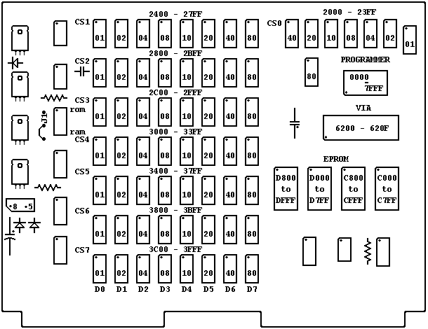
Memory Organization with RAM selected at "2K" and ROM 8elected at "CK".The dot in one corner of each IC chip and Header indicates the proper location of pin 1. The Header has two corners marked, one labelled +5 and one labelled +8. These indicate the proper orientation of the Header when the power supply is providing a regulated +5 volts or an unregulated +8 to +10 volts. ROM and RAM show the location of the switches used to select the base address for the ROM and RAM memories. J1 marks the location of the jumper which must be changed if ROM is placed to start at E000. The line shown is the etched jumper which causes interrupt addresses (FFFA to FFFF) to select the KIM-1 Monitor interrupt vectors (1FFA to 1FFF). This jumper must be removed and replaced by a jumper from the dot near the J to the dot near the 1 if interrupts are to be decoded by the high addresses.