This is the last chapter of the first book on the Junior Computer. The second book will provide some complex program examples and techniques. Before book two can be fully appreciated however, it is advisable to have a taste of what real programming is about. This chapter describes a few interesting programs to enable the JC owner to become more accustomed to programming and operating his/her machine.
The monitor routines, I/O programming, hexadecimal editing and assembling are all described in detail in book two. Before you can run, however, you have to learn to walk — nobody starts their first piano lesson with a piece by Chopin!! With chapter three firmly implanted in your mind we can move on to higher things.
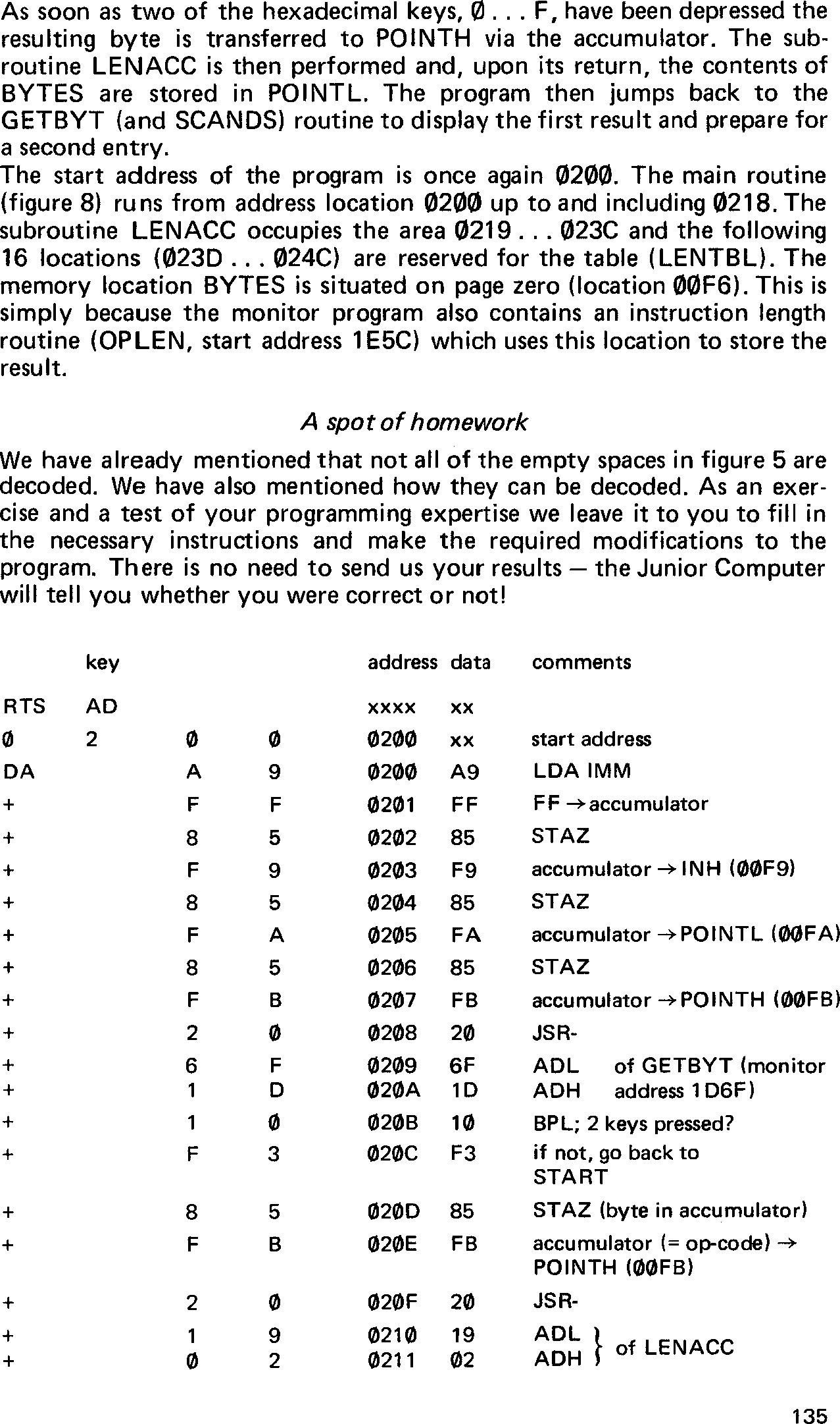
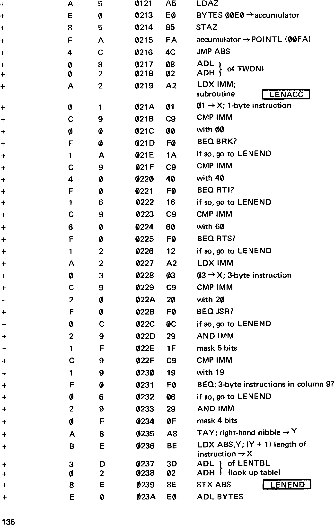
The program examples given in this chapter are accompanied by detailed flow charts and the actual keystrokes required to enter them into the JC. Some more practical tips are also given.
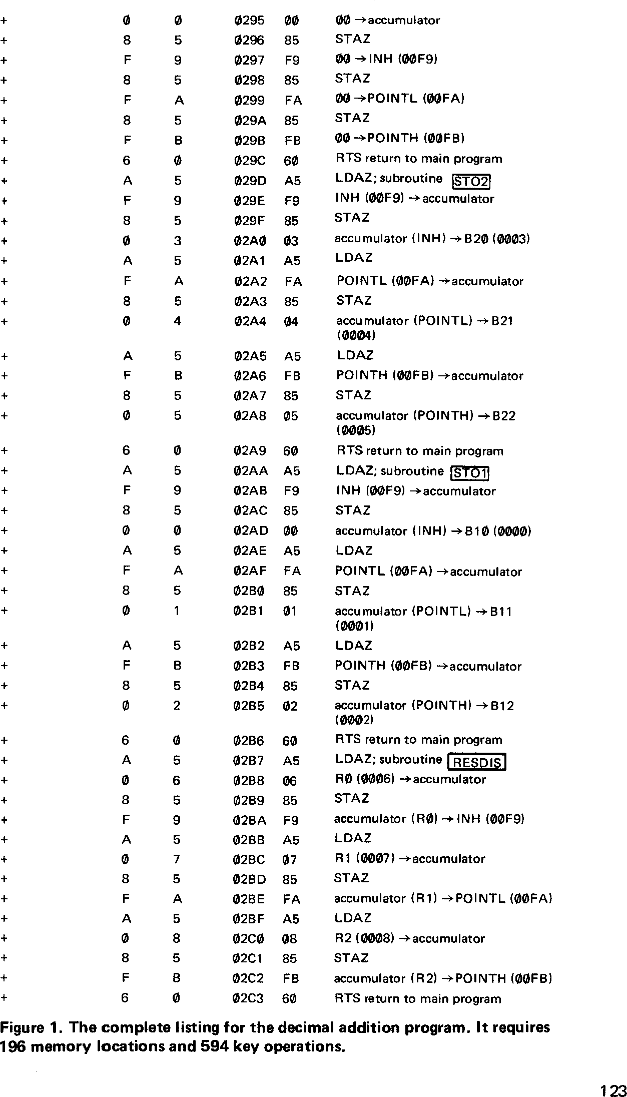
Before a program can be of any use it has to be entered into the memory of the Junior Computer. This program requires a total of 594 keystrokes to fill 196 memory locations — and that is without making any mistakes! Once this has been completed successfully the program can be started and we can perform the decimal addition of two six digit numbers.
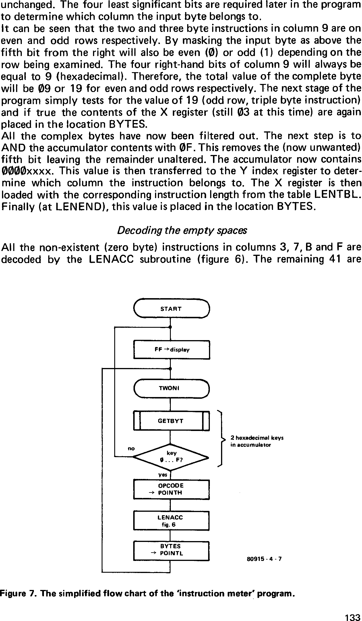
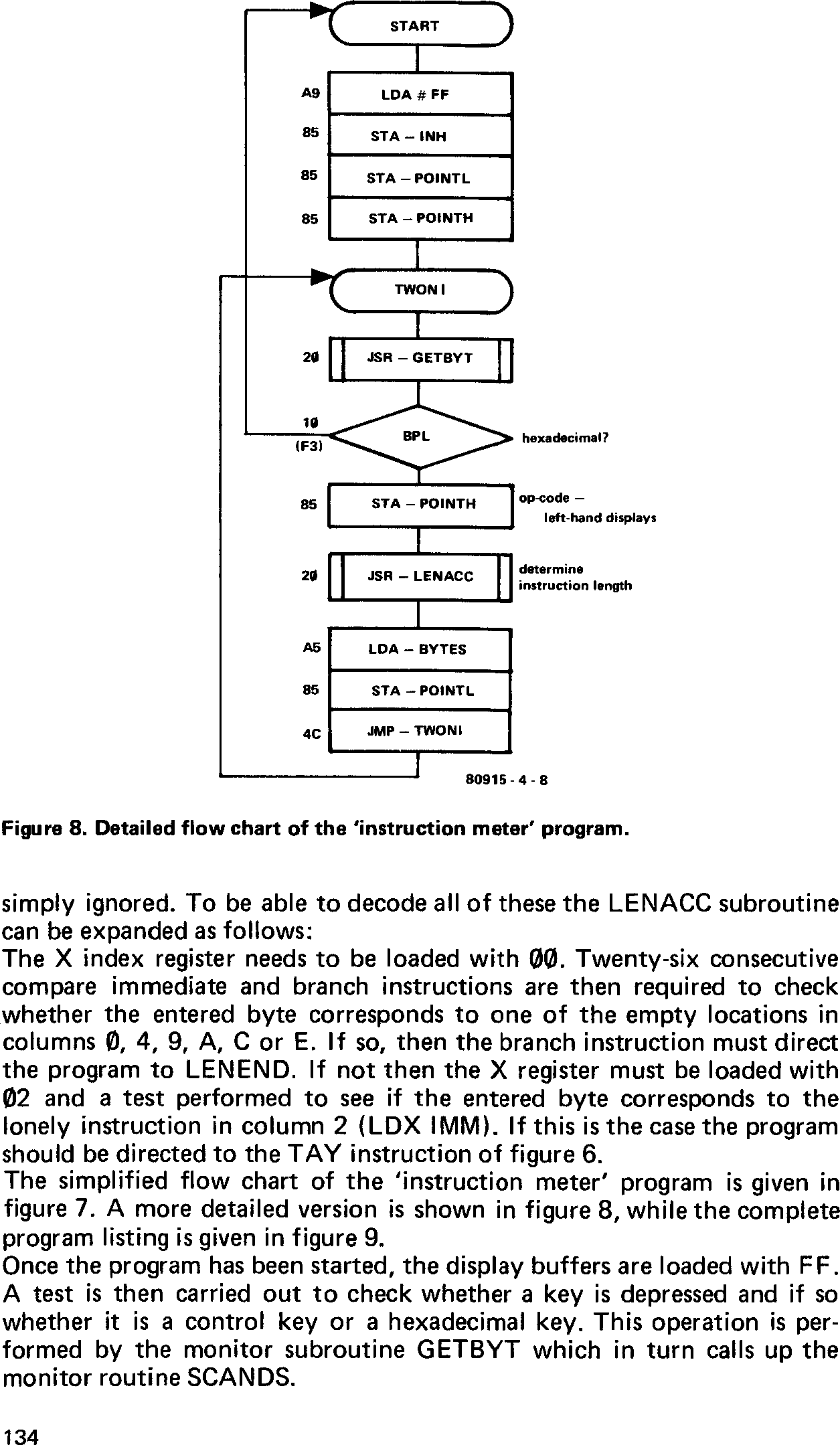
The actual program was mentioned in chapter 3. Figures 14 (the ‘name and address’ of each of the display buffers), 20 (overall flow chart of the program), and 21 (detailed flow charts of the nine subroutines) should be referred to.
The construction of detailed flow charts is a very important phase when developing a program. All decisions etc. can be directly translated into instructions and thus the op-codes and the number of bytes required per instruction can be worked out. In some instances even displacement values can be filled in, but more on that later.
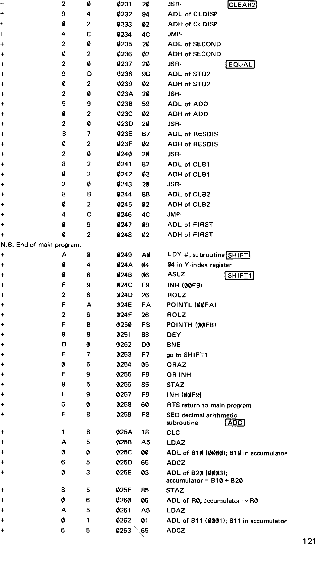
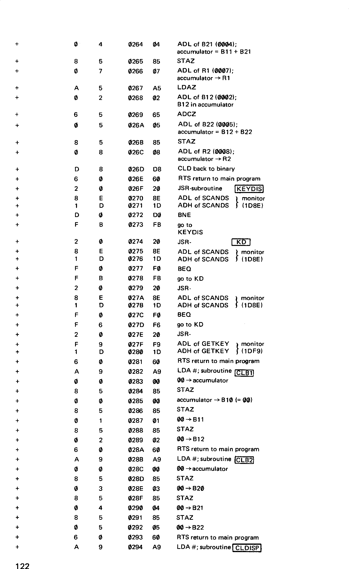
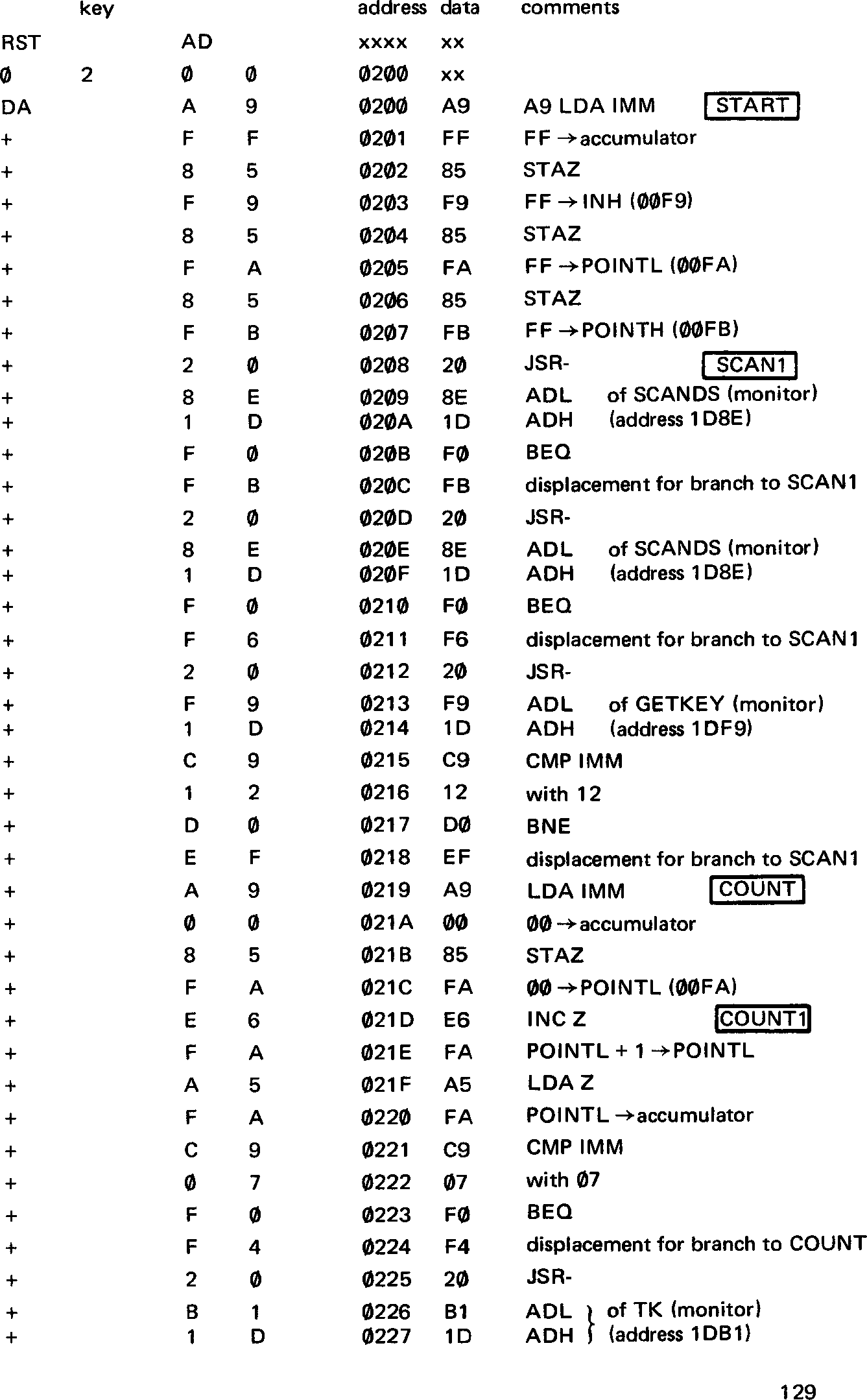
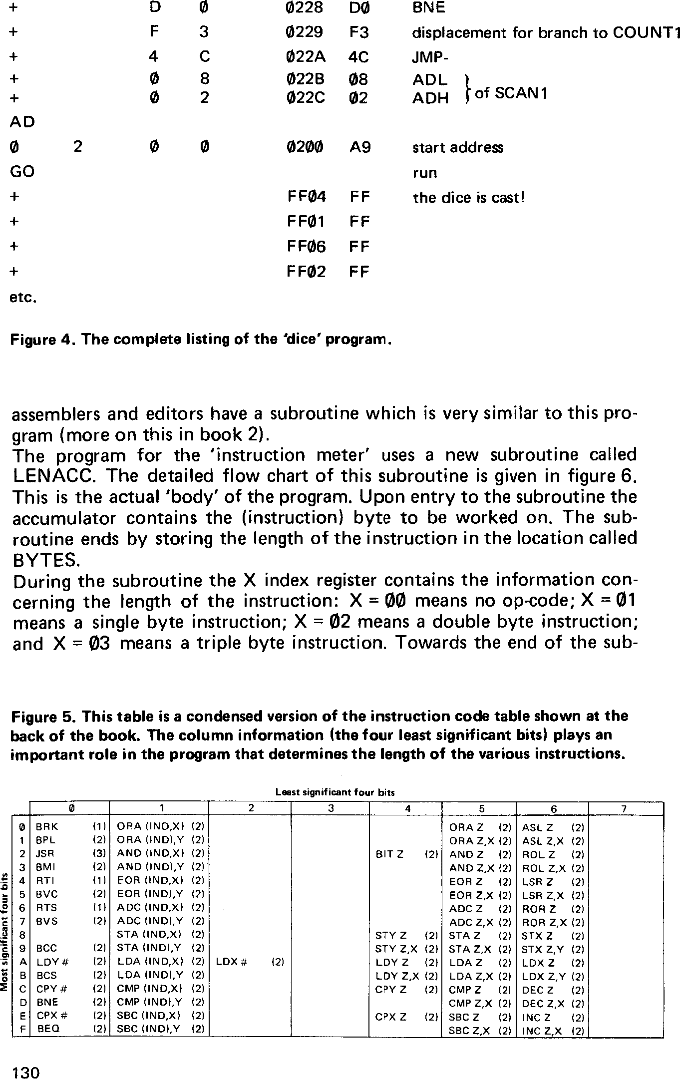
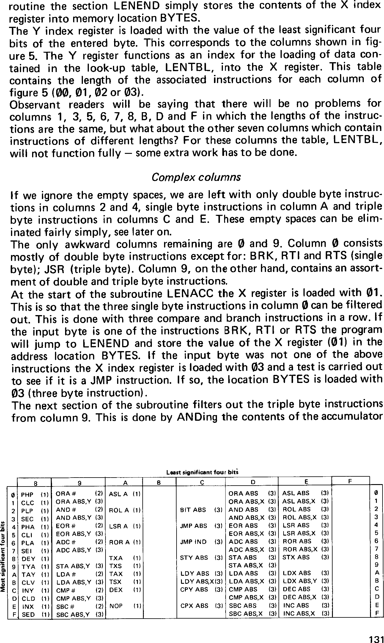
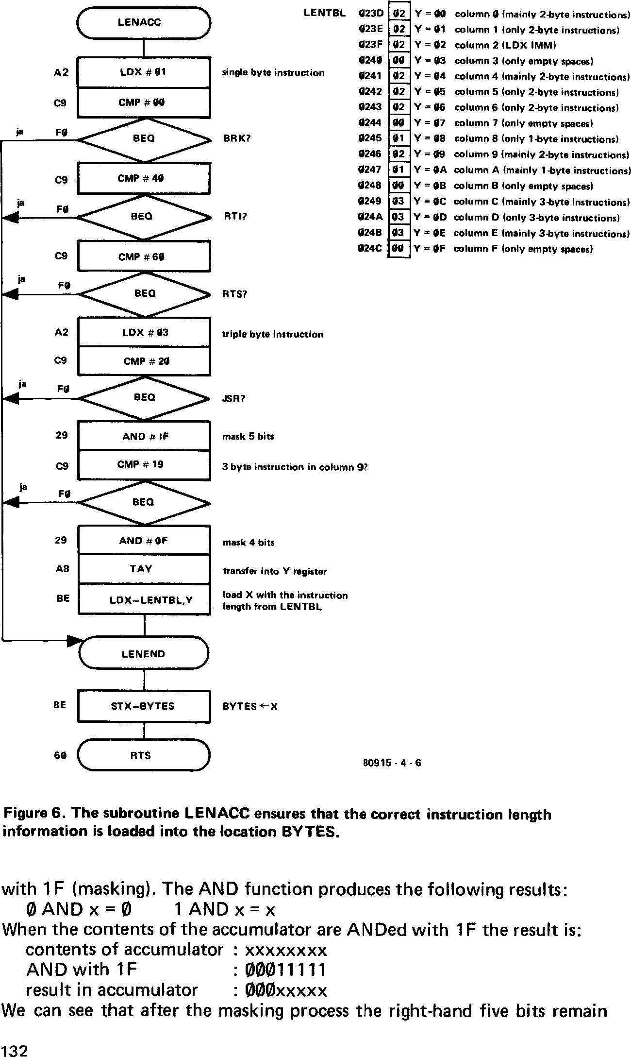
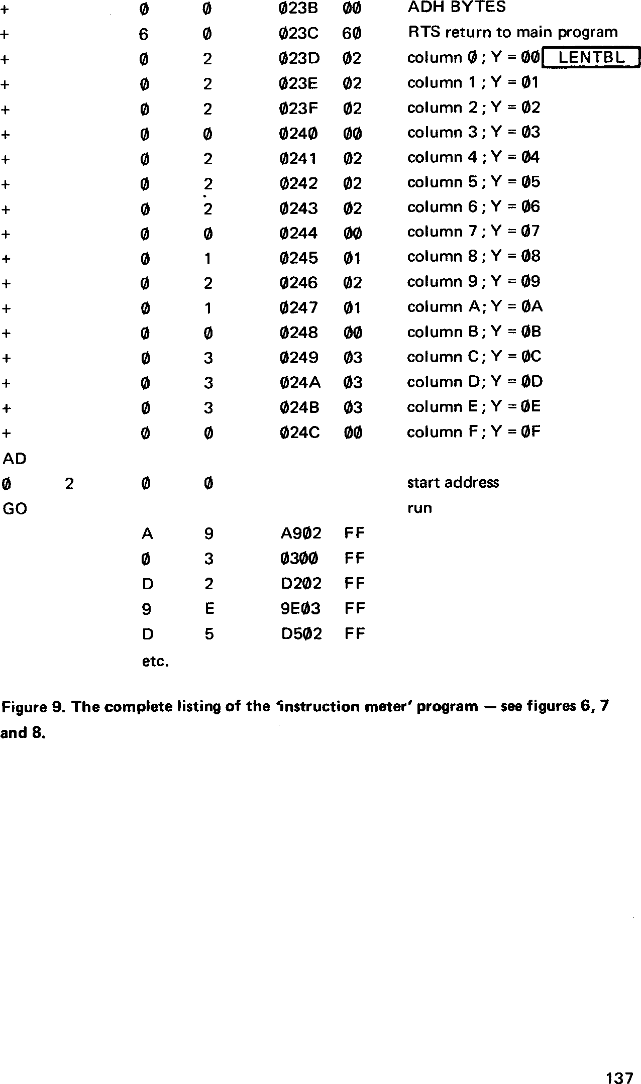
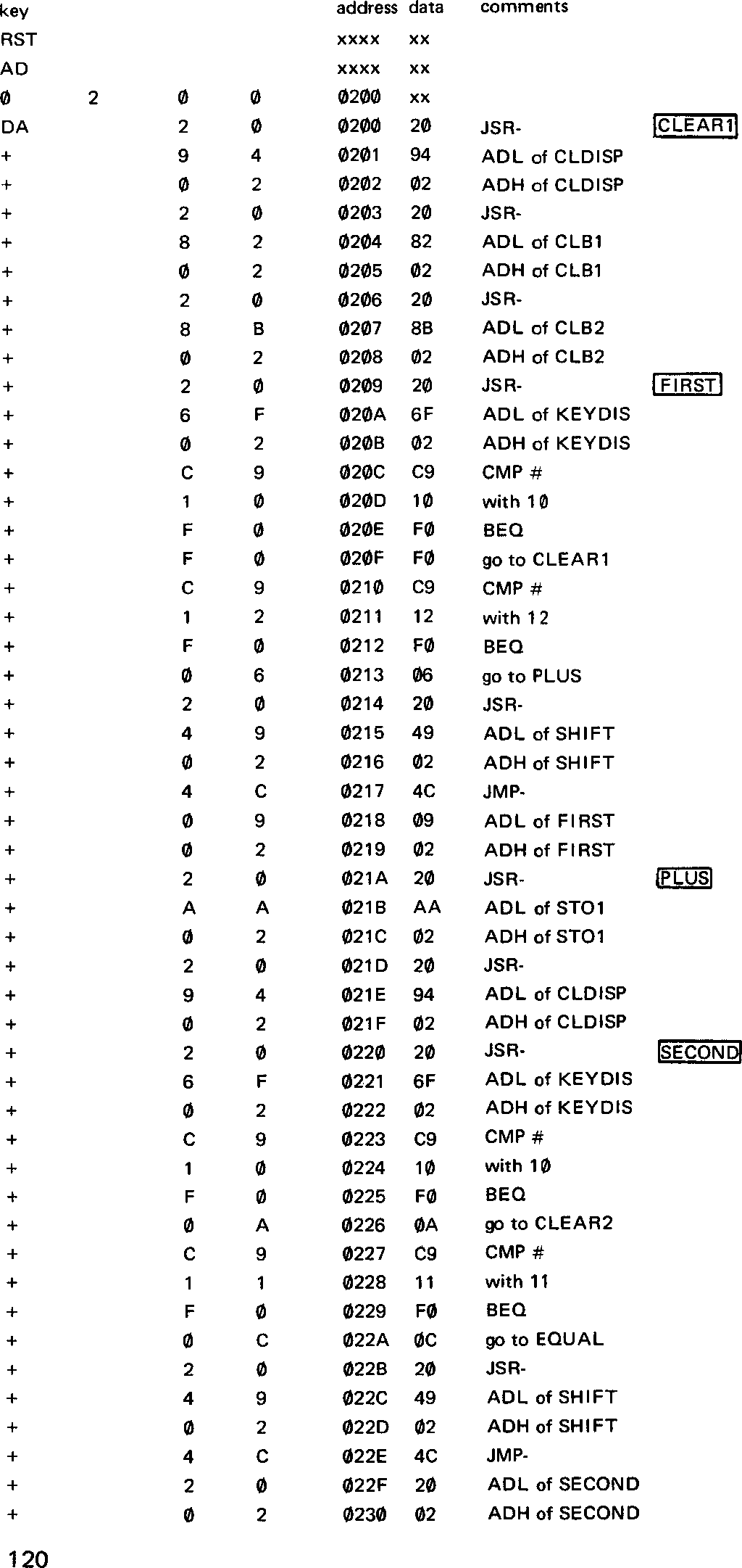
To start with, let us have a look at the program given in figure 1 which consists of the following sections:
locations 0200 ... 0248: main program      (figure 20)
locations 0249 ... 0258: SHIFT  subroutine (figure 21a)
locations 0259 ... 026E: ADD    subroutine (figure 21b)
locations 026F ... 0281: KEYDIS subroutine (figure 21c)
locations 0282 ... 028A: CLB1   subroutine (figure 21d)
locations 028B ... 0293: CLB2   subroutine (figure 21e)
locations 0294 ... 029C: CLDISP subroutine (figure 21f)
locations 029D ... 02A9: STO2   subroutine (figure 21g)
locations 02AA ... 02B6: STO1   subroutine (figure 21h)
locations 02B7 ... 02C3: RESDIS subroutine (figure 21i)
The first instruction (at address location 0200) is going to be a jump to subroutine (JSR) instruction. The actual start address of the subroutine is not always known to begin with. This is because the total length of the main program and the other subroutines has yet to be determined. This brings us to two general and very practical rules:
|
These ‘spaces’ can be filled in later. The second is very important because:
|
These rules are related to the fact that the contents of the program counter are incremented after each instruction. If the processor comes across an empty space, it will either not know what to do, or will certainly misinterpret the intended instruction with (usually) disastrous results. Memory locations can be skipped, by accident, by pressing the + key twice inadvertently. Care must, therefore, be taken when a program is being entered by hand.
Gaps in the program can be filled with the NOP instruction (No OPeration op-code EA). This same instruction can also be entered at various locations on purpose in case extra instructions are required later on. There is nothing more time consuming than having to completely re-enter a long program.
Mistakes can occur at any stage during the development of a program. It is important therefore to be able to check the final version before the program is actually run. This can be accomplished by the JC itself.
The control keys AD, DA and + can be used to check and (if necessary) alter the contents of specific memory locations. A particular location can be examined as follows:
key AD xxxx
where xxxx is the actual address of the memory location to be examined. This address will appear on the left-hand side of the display and the data contained there will be shown on the two right-hand digits. To examine the following memory location the + key is operated. The address displays will then show xxxx + 0001 and the data displays will give the contents of this second location. The complete program can be examined in this way.
If a correction has to be made to the data contained in a particular address location, it is important to ensure that the location is the right one. Once this has been confirmed the DA key can be operated and the correct data can be entered. By operating the + key the data in the following location can be altered if desired, or else locations can be ‘skipped’ by repeatedly pressing the + key. As can be seen, there are adequate provisions for verifying and altering the contents of memory locations, should the need arise (and more often than not it does!).
Various program sections and subroutines are usually given a ‘label’. In figure 1 the labels are shown inside a rectangle on the left-hand side (comment section). When writing out the program the various program sections can be referred to by their label rather than their actual address. As mentioned earlier, at this stage the actual address may not be known. These addresses together with displacement and data values can be filled in once the total number of memory locations required for the program (section) has been worked out.
Not only is it important that a program occupies a fixed number of (consecutive) memory locations, but it is also important that program sections do not overlap. It is imperative that the program does not run into the memory area reserved for the monitor program.
There is no rule that subroutines must follow straight on from where the main program finishes, which is the case in figure 1. It is always possible to have a number of unused memory locations situated between the main program and the subroutine. This is especially true of short programs. On the other hand, when developing longer programs it is advisable to use memory space as economically as possible. How many memory locations can we actually use?
|