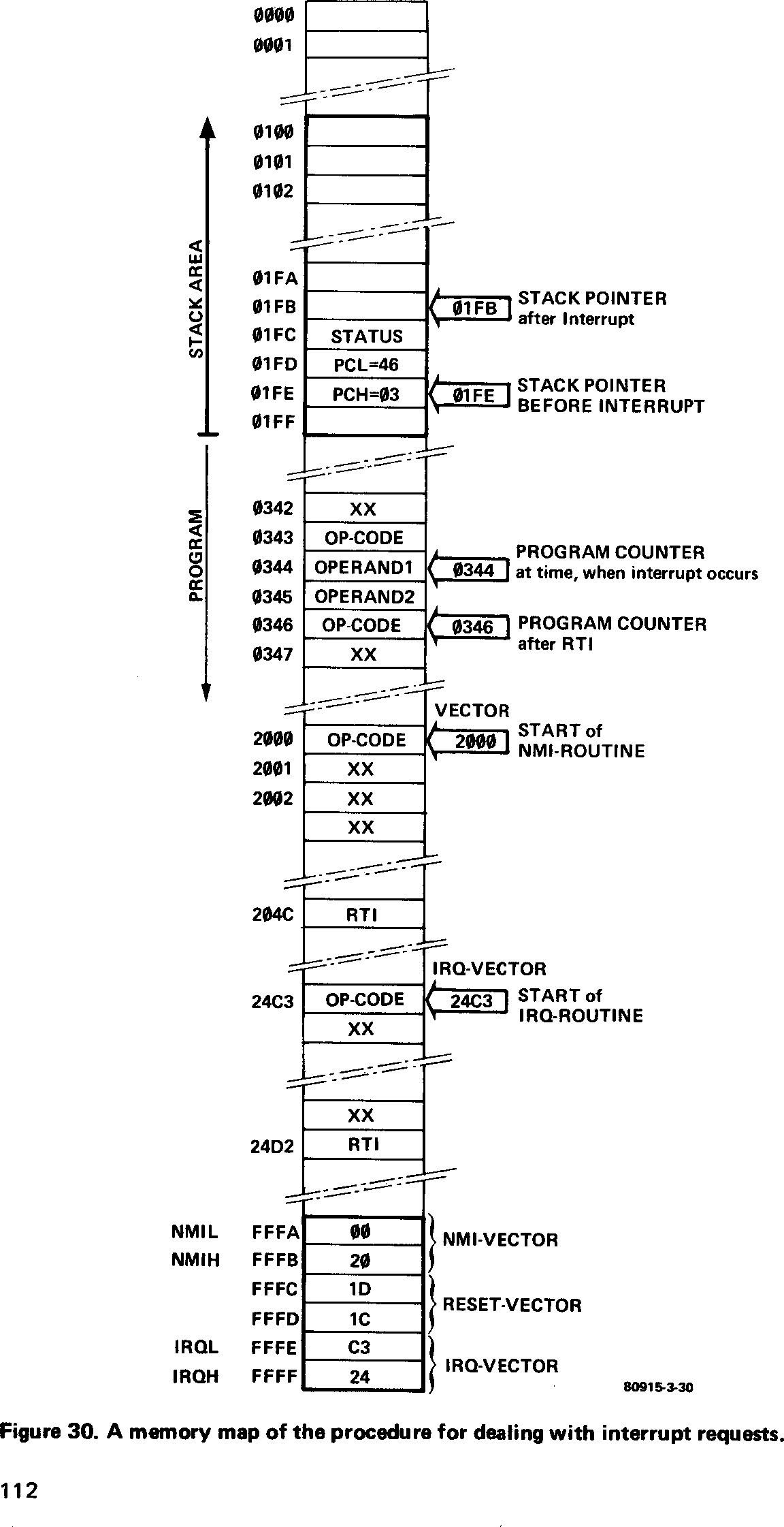
Now that the Junior Computer is complete and operational, and the background information from chapter 2 has been digested, we come to the ‘user’s manual’. What can we do with the JC and how do we go about it? These questions will be answered in this chapter.
Before we are able to use the JC we must have some knowledge of the more serious aspect of programming. Do not worry however, as programming can be quite fun. By the end of this chapter it should be possible to develope your own (short) programs and to make the JC perform more or less as you want it to. Chapter 4, on the other hand, deals with more complex programming and gives some programming ‘tricks’ to further simplify matters. But first . . .
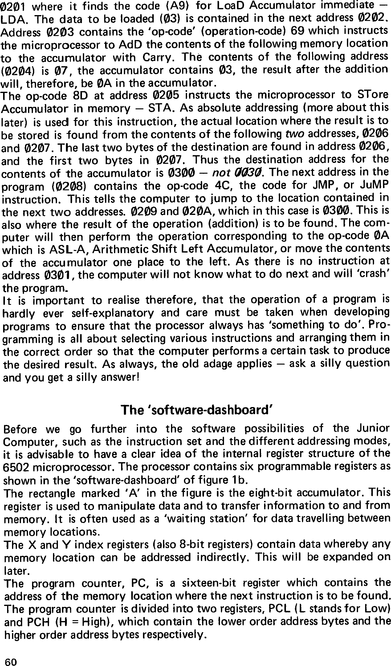
As we know, the hardware ‘dashboard’ consists of two toggle switches, 23 keyboard switches and 6 seven-segment displays — as shown in figure 1a. Once the system has been switched on, the RST key is depressed to initialise the microprocessor. The monitor program will then scan the keyboard to check whether or not any of the switches are being depressed. If one of the hexadecimal switches is pressed (0 … F), this will be indicated on the display. The four displays on the left-hand side will show the address location in hexadecimal code and the two right-hand ones will give the ‘contents’ of that location. In principle, all the address locations from 0000 … FFFF are possible.
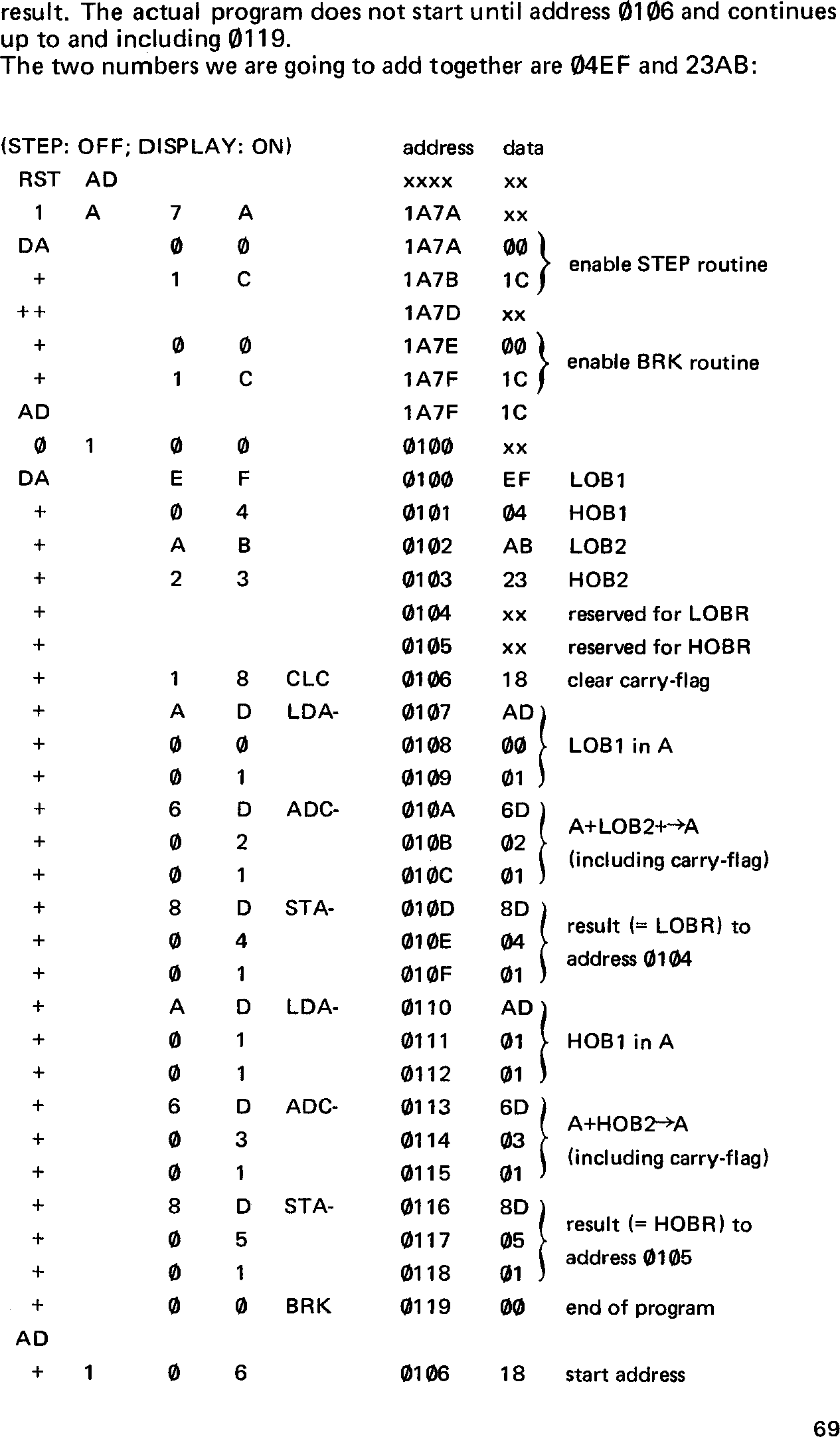
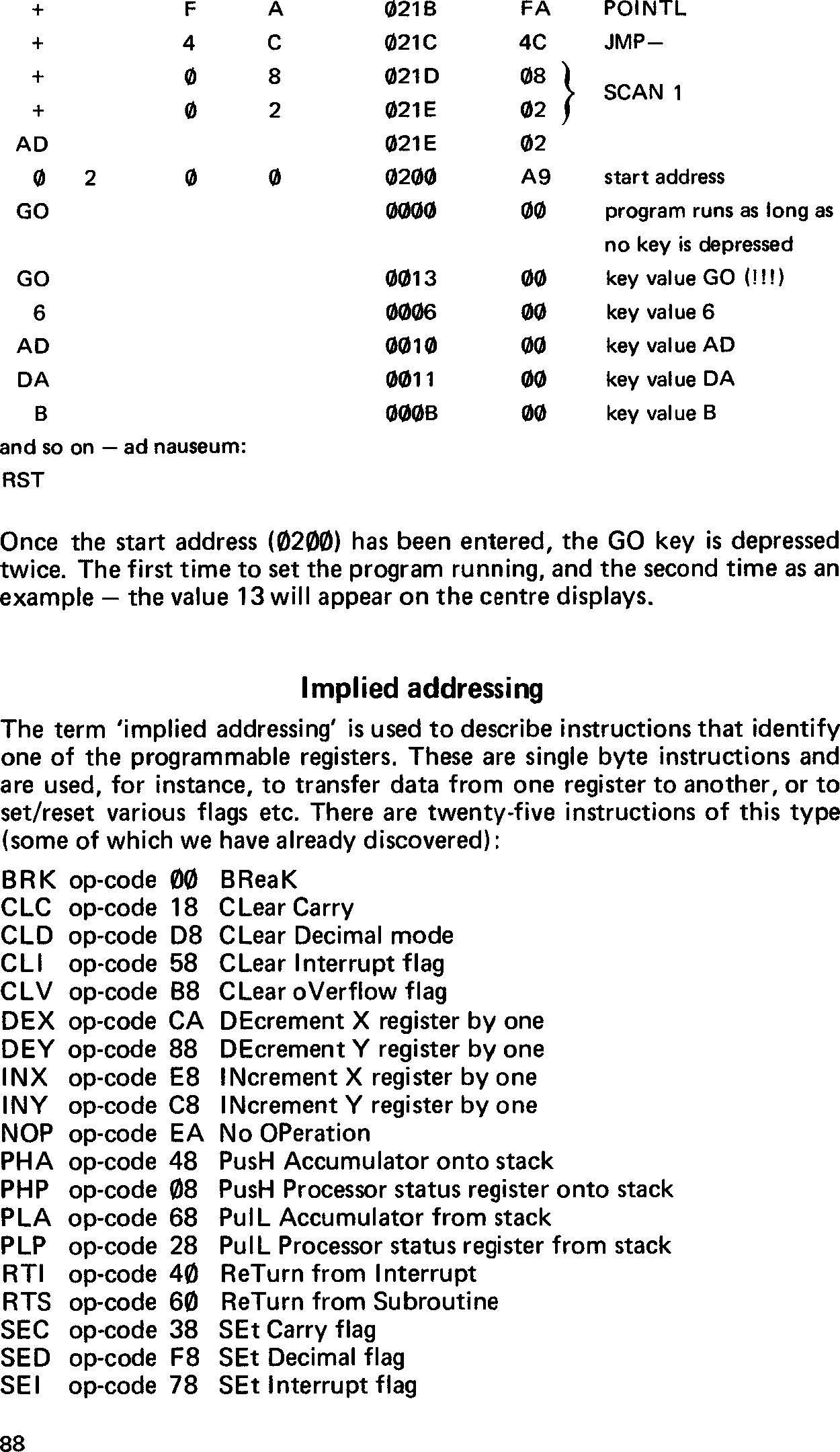
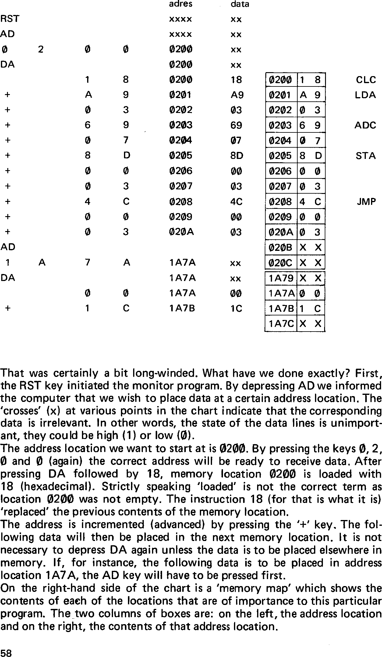
Take for example that we want to enter certain data into a given area of memory. From address location 0200 on we want to enter 18, A9, 03 etc. The sequence of operations is as follows:
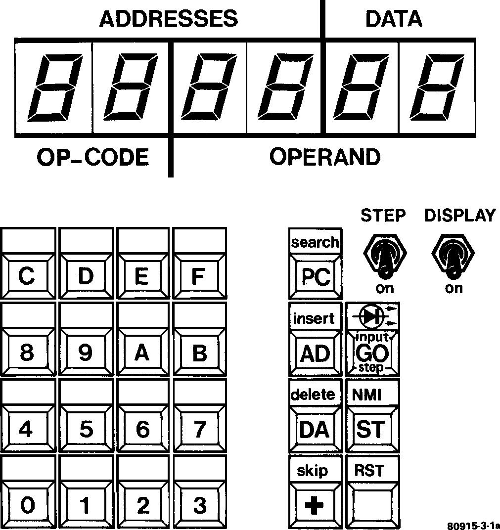
Figure 1a. The ‘hardware dashboard’ of the Junior Computer. Besides the sixteen hexadecimal keys and the seven control keys, there are two function switches. The text in small letters indicates the editing functions that the JC can perform. Under normal conditions the four left-hand displays show a particular address location and the two right-hand displays the data contained at that address.
We should now be familiar with the following keyboard switches:
0 ... F, for entering data and address information;
RST, which initialises the microprocessor and activates the monitor program and the display;
AD, which instructs the computer to go into the address mode for loading one or more address locations;
DA, which instructs the computer to go into the data mode;
+, which advances the address location by one. The mode (address or data) is not affected.
Note: As with most pocket calculators, the address and data information is keyed in from left to right, but the display will appear to move from right to left.
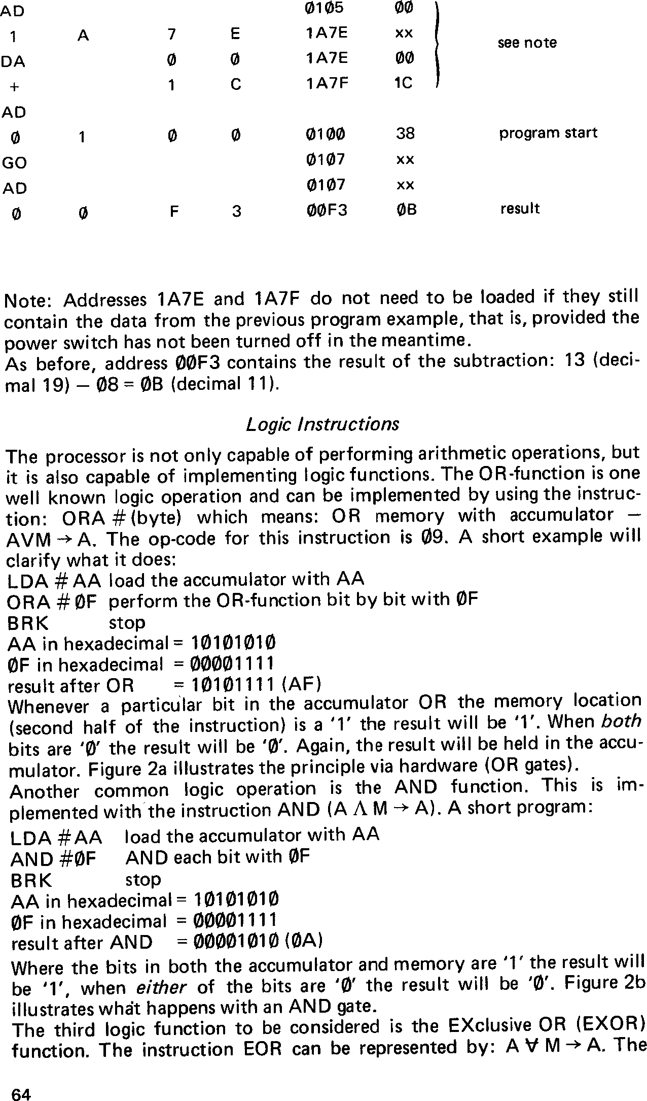
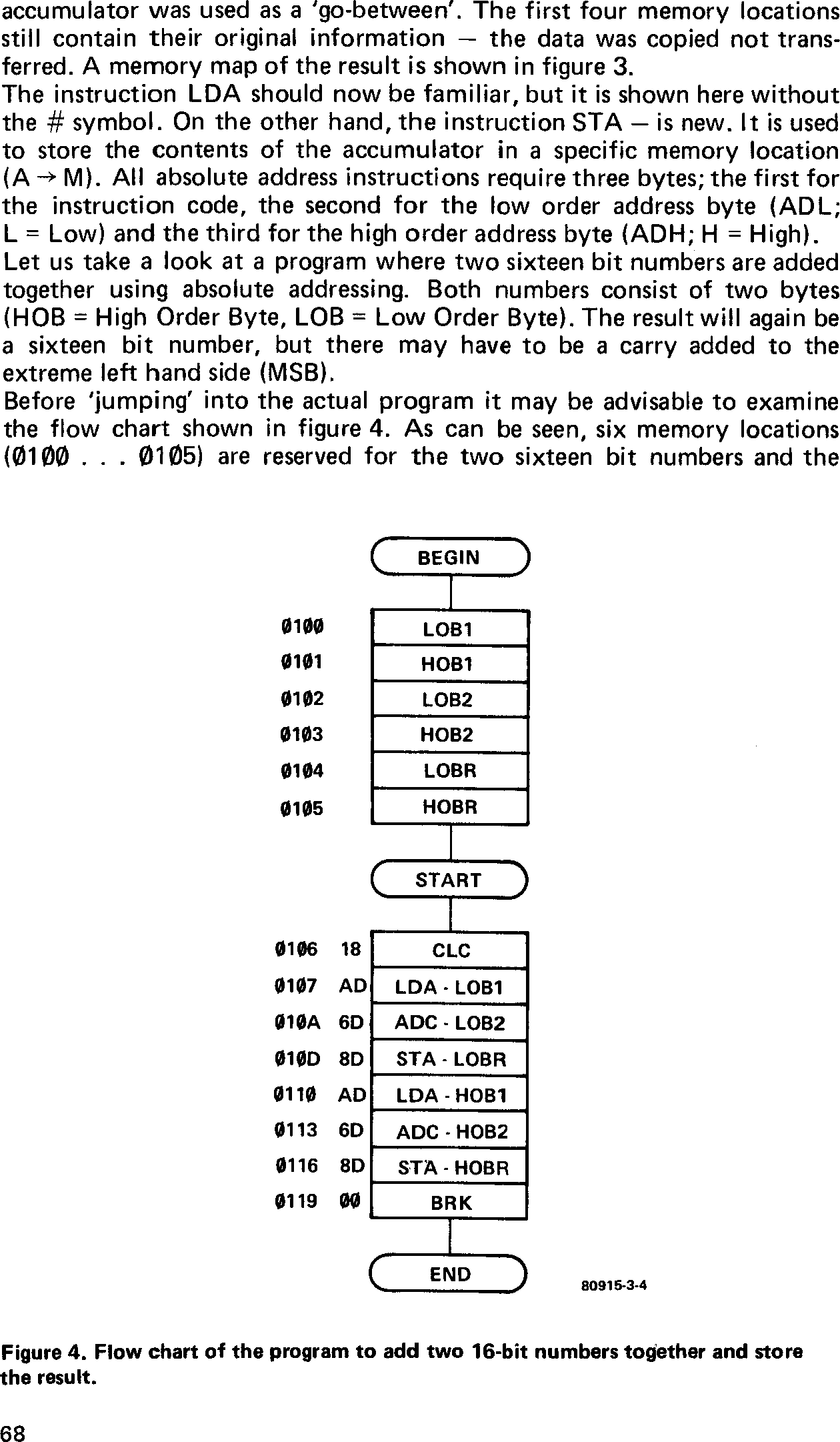
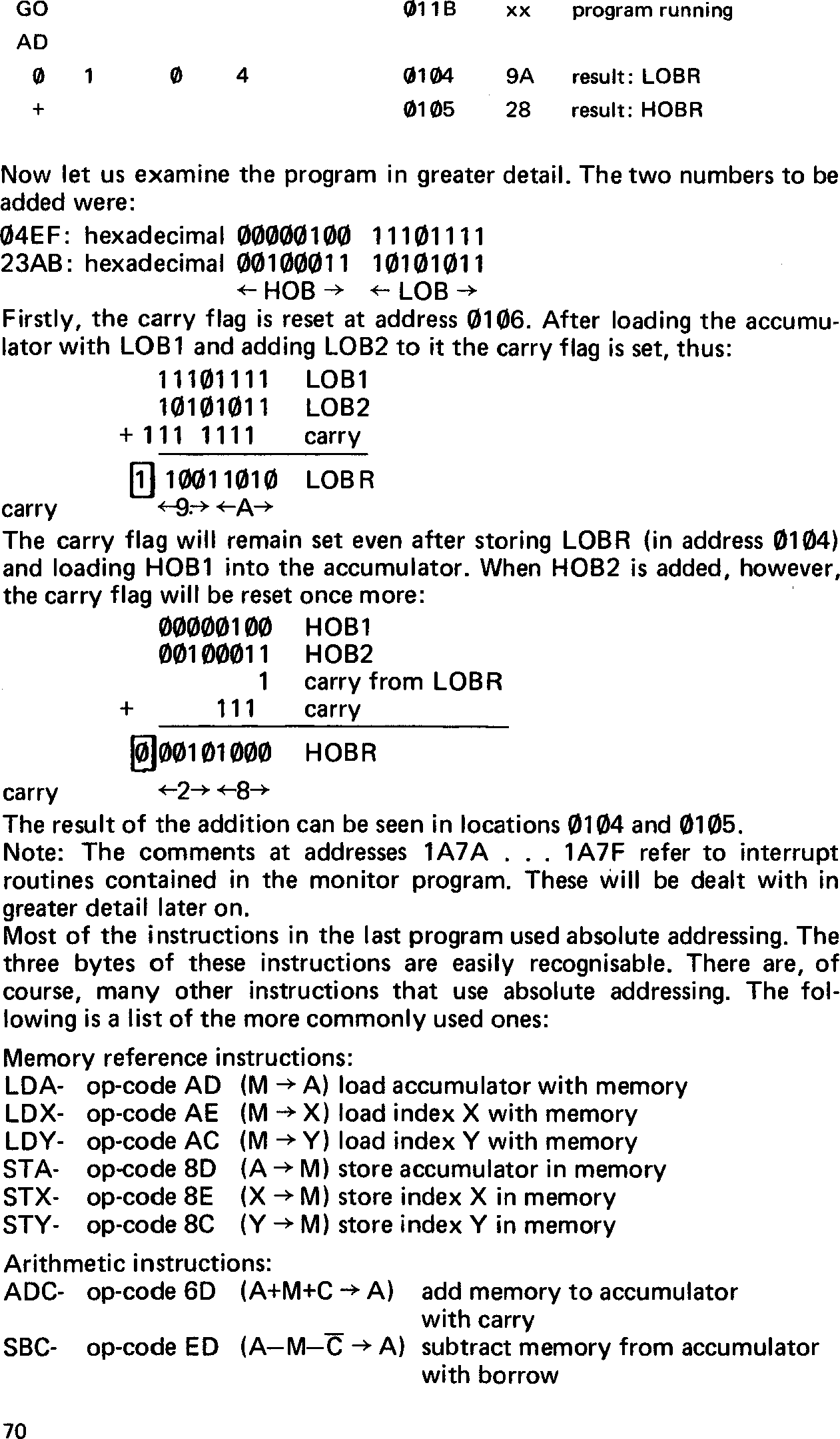
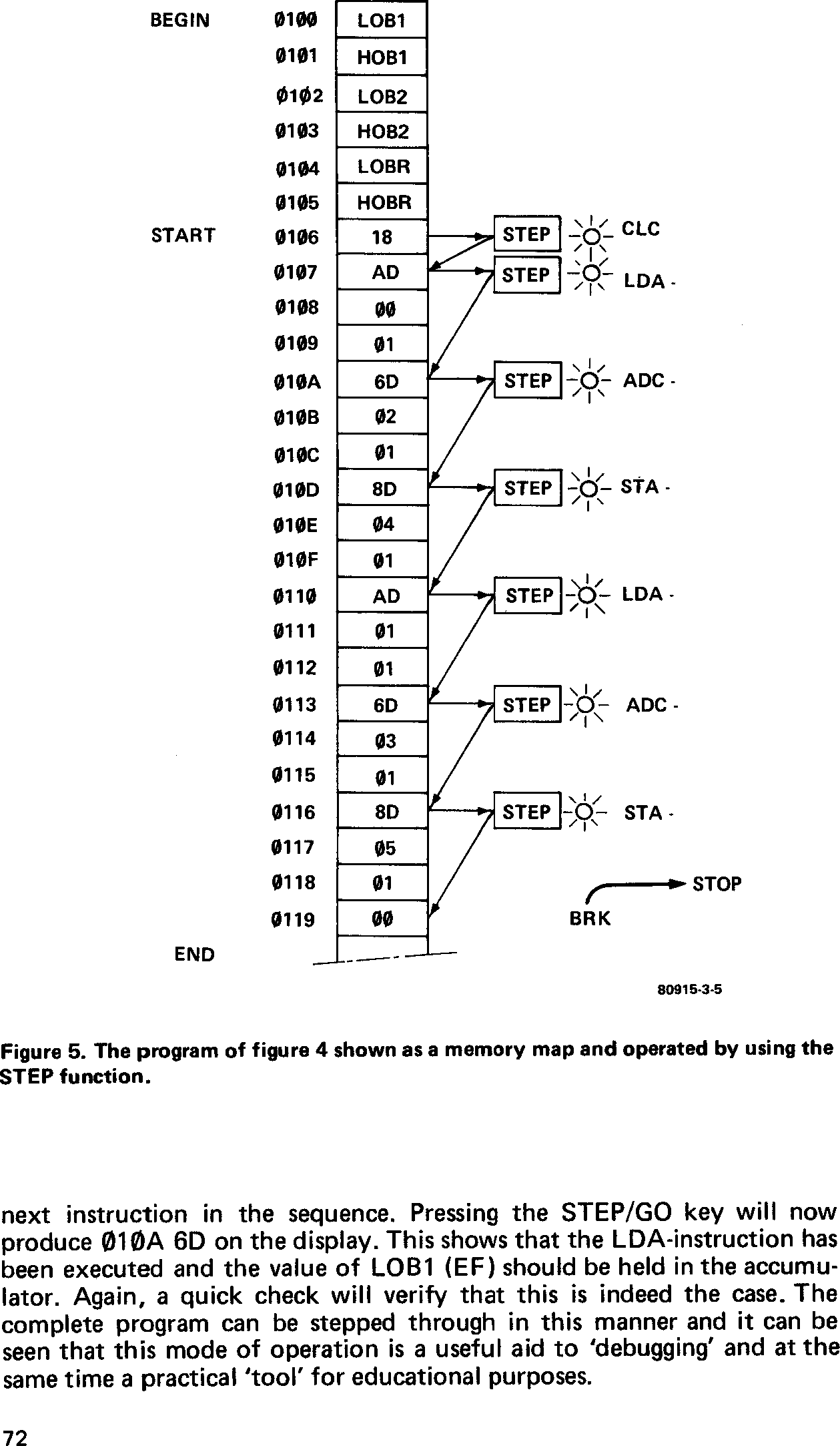
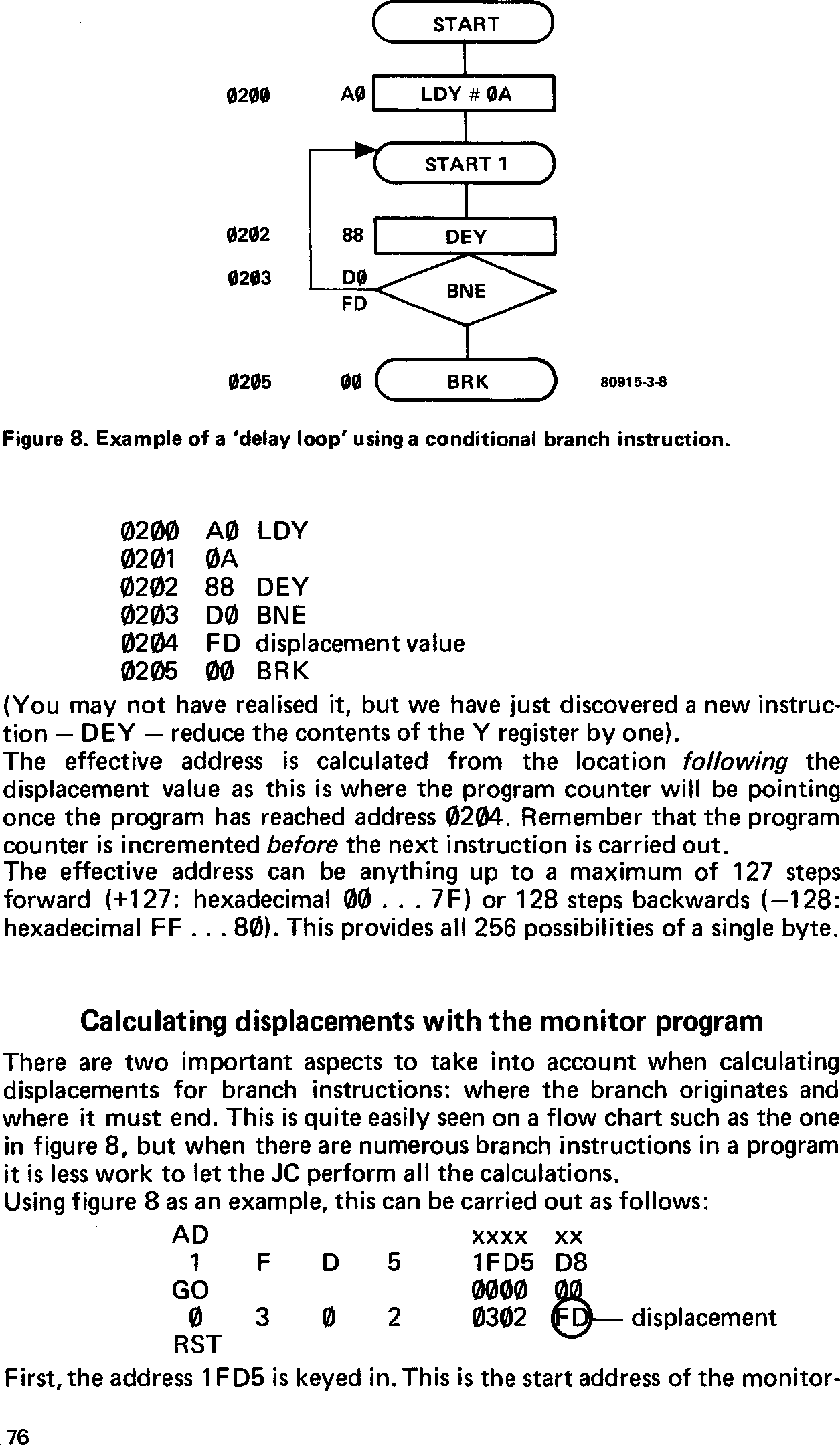
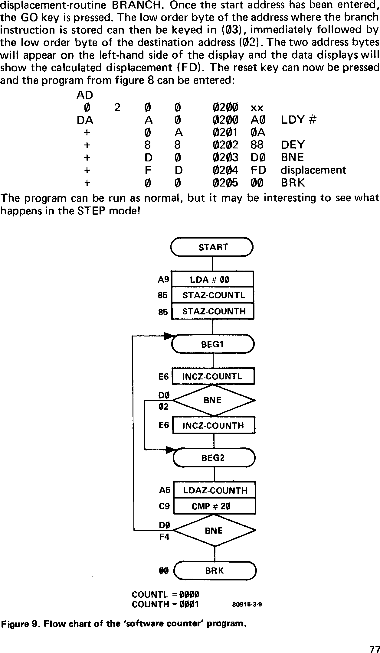
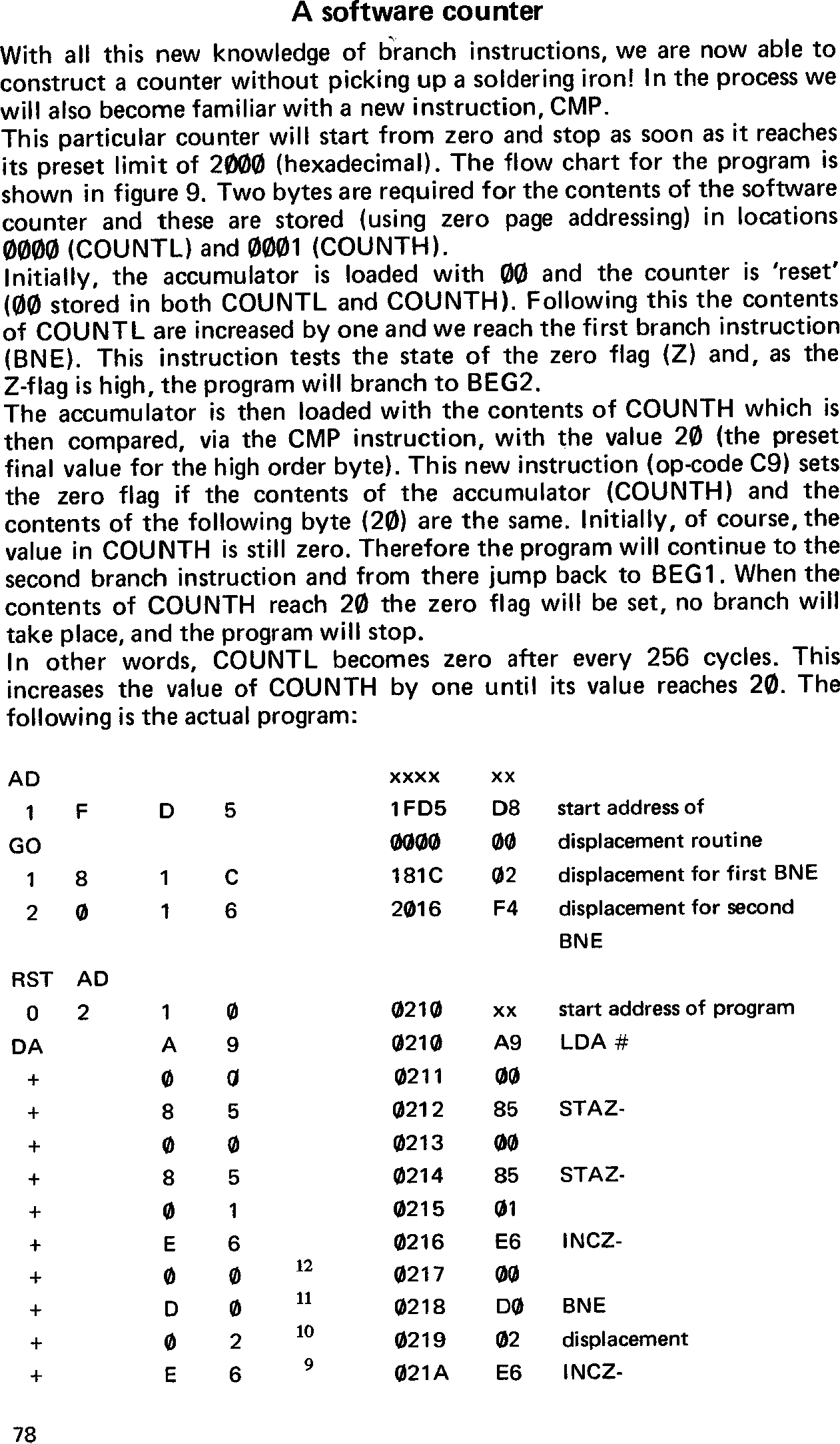
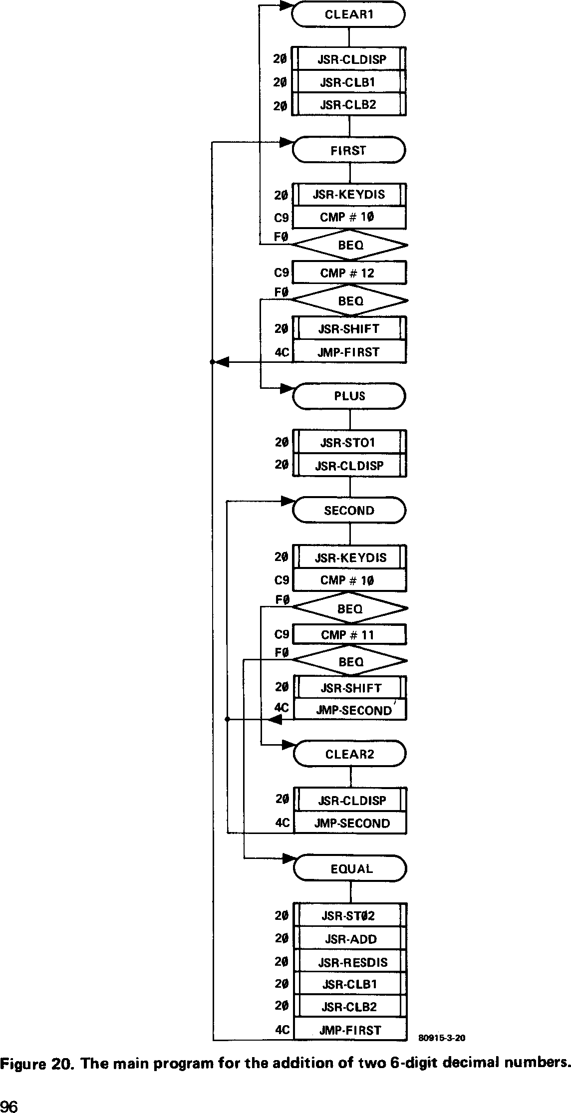
As mentioned earlier, all the information we have just entered is not a random set of hexadecimal figures, but a real program to add two numbers together and store the result. This is what happens:
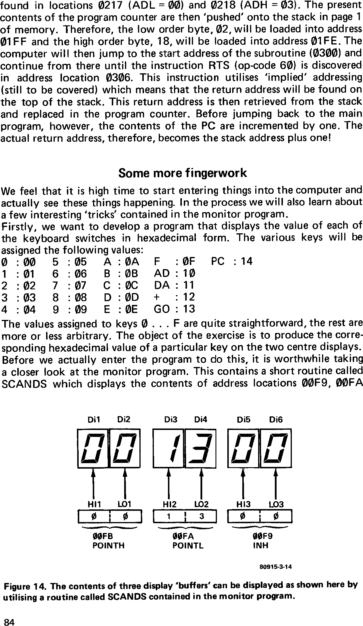
The first operation code, 18 (at address location 0200), is the code for the instruction CLC-CLear Carry. The computer then moves on to address